EP1471335A2 - Sensor mit Hinter-Gewinde zur Befestigung an einem Behältnis sowie Lot-Druck-Kontakt zur Abschirmung - Google Patents
Sensor mit Hinter-Gewinde zur Befestigung an einem Behältnis sowie Lot-Druck-Kontakt zur Abschirmung Download PDFInfo
- Publication number
- EP1471335A2 EP1471335A2 EP04006793A EP04006793A EP1471335A2 EP 1471335 A2 EP1471335 A2 EP 1471335A2 EP 04006793 A EP04006793 A EP 04006793A EP 04006793 A EP04006793 A EP 04006793A EP 1471335 A2 EP1471335 A2 EP 1471335A2
- Authority
- EP
- European Patent Office
- Prior art keywords
- sensor
- housing
- sensor device
- fastening
- container
- Prior art date
- Legal status (The legal status is an assumption and is not a legal conclusion. Google has not performed a legal analysis and makes no representation as to the accuracy of the status listed.)
- Granted
Links
Images
Classifications
-
- G—PHYSICS
- G01—MEASURING; TESTING
- G01L—MEASURING FORCE, STRESS, TORQUE, WORK, MECHANICAL POWER, MECHANICAL EFFICIENCY, OR FLUID PRESSURE
- G01L19/00—Details of, or accessories for, apparatus for measuring steady or quasi-steady pressure of a fluent medium insofar as such details or accessories are not special to particular types of pressure gauges
- G01L19/14—Housings
-
- G—PHYSICS
- G01—MEASURING; TESTING
- G01L—MEASURING FORCE, STRESS, TORQUE, WORK, MECHANICAL POWER, MECHANICAL EFFICIENCY, OR FLUID PRESSURE
- G01L19/00—Details of, or accessories for, apparatus for measuring steady or quasi-steady pressure of a fluent medium insofar as such details or accessories are not special to particular types of pressure gauges
- G01L19/0007—Fluidic connecting means
- G01L19/003—Fluidic connecting means using a detachable interface or adapter between the process medium and the pressure gauge
-
- G—PHYSICS
- G01—MEASURING; TESTING
- G01L—MEASURING FORCE, STRESS, TORQUE, WORK, MECHANICAL POWER, MECHANICAL EFFICIENCY, OR FLUID PRESSURE
- G01L19/00—Details of, or accessories for, apparatus for measuring steady or quasi-steady pressure of a fluent medium insofar as such details or accessories are not special to particular types of pressure gauges
- G01L19/14—Housings
- G01L19/148—Details about the circuit board integration, e.g. integrated with the diaphragm surface or encapsulation
Definitions
- the invention relates to a sensor, in particular Pressure sensor for attachment to a container with the generic term Features of claim 1, with the preamble Features of claim 7 or method for mounting a sensor.
- Previously known sensors designed as pressure measuring devices have a housing with a threaded connection, through which the housing into a container through opening screwed from the outside to the inside of the container becomes.
- Pressure sensors are known as polysilicon pressure sensors, which in connection with a diaphragm seal liquid be used, or pressure sensors, which with a ceramic capacitive pressure sensor element are built up.
- Systems with ceramic capacitive pressure sensor elements are constructed such that the pressure sensor element via a fastening device from the outside of the container the inside of the container, d. H. for process connection built in and thus against the pressure effect by the monitoring medium is supported in the container.
- a disadvantage such embodiments is that by Container through opening and through the inserted therein Front opening of the sensor housing only pressure sensor elements with a correspondingly significantly smaller one Diameters fit, which results in a reduction in measurement accuracy results. The measurement accuracy is reduced in that the ratio of basic capacity to measuring capacity behaves less favorably than with a larger diameter.
- the object of the invention is a pressure sensor to propose with a structure that is proportionate to the front outside diameter of the sensor housing if possible large diameter of the actual sensor element as Sensor device enables. Furthermore, preferably with View of the arrangement of individual components of the sensor inside the housing proposed an improved arrangement which are also of generally smaller dimensions Structure of the housing allows. Advantageously, should Methods for manufacturing such sensors are proposed become.
- a pressure sensor advantageously consists of a housing with a longitudinal axis, a front or front and in the installed state in a container through opening protruding sensor device and one Sensor device attachment for attaching the sensor device on or in the housing.
- the sensor device fastening device encompasses the sensor device fastening device the sensor device from the front from at least in sections of the front Edge area of the sensor device, which makes this a front Experience support.
- the sensor device fastener advantageously goes without magnification the outer circumference by means of an appropriate fastening into the housing.
- An appropriate attachment is included a joining, in particular a thermal joining.
- the housing In the rear area of the sensor device is on the peripheral wall the housing has an external thread for fastening of the housing in an internal thread of a container through opening educated. It is convenient to do so the outer circumference of the sensor device fastening device less than or equal to the core diameter of the thread, so that almost complete utilization of the diameter of the container passage opening with a view on the outside diameter of the sensor device becomes. Only those guided to the side of the sensor device Walls of the sensor device fastening device and support elements encompassing the front limit the effectively usable area of the sensor device.
- the sensor device is advantageously from the front of the housing or those inside other components attached and connected, whereby to hold the sensor device from the front the sensor device fastening device put on and is attached to the housing.
- the attachment takes place expediently as a joint, with as little thermal as possible Energy and the lowest possible electromagnetic fields, advantageously no electromagnetic fields at all to the metal parts of the sensor device fastening device to be joined and melt the housing together. This will destroy the pressure sensor element from a ceramic material as well as directly adjacent seals made of an elastomer avoided.
- a sensor in which the outer diameter the sensor device in relation to the core diameter an external thread of a sensor housing fastening device is only slightly less.
- the ratio of the outer diameter is preferably Standard pressure sensor elements as a sensor device for standard thread core diameters with the smallest possible distance and with a sensor device fastening device half the wall thickness of the diameter difference can be achieved.
- a pressure sensor element 28 mm known, such a sensor element with the arrangement described on a sensor housing a core diameter of 30.29 mm as a typical bore core diameter for a container through opening or one corresponding housing fastening device in the form of a External thread can be used.
- a module housing z. B. an electronics housing with a solderable To design coating or surface so that a compression, in particular a pressing together with a fastening element or some other element Dissolution and displacement of the solderable coating causes and thereby an electrical contact after their solidification to protect the electronics against electromagnetic influences and / or designed to ensure equipotential bonding becomes. This avoids the provision of separate contacts, Connection elements and connecting elements.
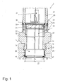
- Fig. 1 shows a section of a container 1, on which a sensor 2 is in particular releasably attached.
- the container 1 has a wall 11, the one shown Section, for example, a flange or a other screw fastening as an element of an actual Container 1 can be formed.
- a container through opening 13 to the outside of the container 1 indicates the container through opening 13 a container internal thread 14, which serves to screw in the sensor 2.
- a container internal thread 14 which serves to screw in the sensor 2.
- the container through opening 13 also has a circumferential container groove 15 on the inside, in which an elastic seal, e.g. B. an O-ring 16 so is inserted that none of the inside of the container 12 Medium through the space between the container through opening 13 and the sensor 2 used therein Outside occurs.
- the sensor 2 consists of a housing 20, which is shown in the Embodiment of a variety of individual components is composed.
- the example housing 20 has a rear housing part 21 and a front Housing part 22, the front or the side or direction of components in the direction of the inside of the container 12 and on the back the opposite direction in the built-in Represents state. The directions are only used to illustrate the alignment of individual Components to each other.
- the front section of the front housing part 22, 20 is a housing fastening device 23 in the form of a External thread 23 formed. With the help of this external thread 23, the sensor 2 is in the internal thread 14 of the container through opening 13 screwed to the sensor 2 on the container 1 to attach.
- the actual sensor device 24, in particular a ceramic pressure sensor element 24, is attached to the end or front end of the front housing part 22, 20, in particular used in a receiving recess.
- a sensor device fastening device 25 is used, which is essentially annular and encompasses the sensor device 24 laterally, starting from the front side of the front housing part 22, 20, extending beyond the front side of the sensor device 24.
- the thickness of the sensor device fastening device 25 is kept as thin as possible in order to offer the sensor device 24 a secure hold on the housing 20, 22 on the one hand and on the other hand to enable the diameter d s of the sensor device 24 to be almost as large as possible Inner diameter d B of the container through opening 13 is formed. This enables the use of a sensor device 24 with an optimally large diameter d s , which ultimately counteracts the usual reduction in measuring accuracy and increases the measuring capacity.
- the sensor device fastening device 25 one or more protrude inwards into the container through opening 13 or inward projections 26.
- this is inward Projection 26 as a bent and circumferential collar 26 the otherwise cylindrical or ring-shaped sensor device fastening device 25 trained.
- the front surface of the sensor device 24 against mechanical Protecting damage is one or more Seals 27, preferably a circumferential sealing ring 27 between the inward projection 26 and the front the sensor device 24 used.
- a joint 28 is formed.
- the joint 28 of the housing ring as a sensor device fastening device 25 to the front housing part 22, 20 occurs when assembling with so little thermal Energy in the form of e.g. B. light waves that one hand melt the two parts together without creating one Destruction, especially as a ceramic pressure sensor element trained sensor device 24 or directly adjacent seal 27 comes from an elastomer and on the other hand, no electromagnetic fields arise which destroy sensor electronics 33 connected in sensor 2 can.
- the elements to be joined are corresponding 25, 22 preferably metal parts, which in particular Light waves melted together as thermal energy become. The use of other materials with accordingly suitable processes for their fusion or connection with possibly adhesive materials is possible.
- the fastening of the sensor device 24 designed in this way on the housing 20 or alternatively a sensor fastening device for attaching the sensor to the container 1 without other components shown offers in addition to the simple Assembling also benefits in terms of space usable area of the sensor device 24.
- a ceramic capacitive standard pressure sensor element with a diameter of z. B. 28 mm are attached in this way, the core diameter for a conventional Thread G1 (according to DIN ISO 228-1) with 30.29 mm of the external thread of the housing 23 or the container internal thread 14 in the container through opening 13 can be provided.
- the sensor device fastening device 25 remains a sufficient wall thickness of 1 - 1.14 mm for reaching around the sensor device 24.
- the rear of the Sensor device 24 formed wall of the front Housing part 22 has sufficient strength to in the area the container internal thread 14 sufficient stability and Offer stop for the sensor 2. Ultimately, this will help allows the pressure sensor element from the process side from the fastening or the front housing part 22, 20 introduced and in the outer direction of this is supported, wherein the pressure sensor element 24 of the joined Housing ring as a sensor device fastening device 25 with the outside diameter of in particular 30 mm and the seal 27 is held.
- a pressure compensation line 30 through the Interior of the housing 20 and other components, in particular the sensor electronics 33 around the air balance to ensure pressure sensor element like this by itself taken is known.
- one or more lead from the sensor device 24 Lines as electrical connections 32 to the sensor electronics 33, which inside an electronics housing 34 of the housing 20-22 is included.
- the electrical one Connections 32 lead to a first circuit board 35 and on this to corresponding conductor tracks and / or electronic Components.
- the electrical connection between the two boards 35 and 36 can, as mentioned, take place via the electronics housing 34.
- the electronics housing 34 expediently on the inner wall of the electronics housing 34 a necessary number of each other insulated conductor tracks applied.
- These traces which are indicated in FIG. 1 by the reference symbol 38, can for example by on the edge of the boards 35 and 36 arranged contacts, e.g. Sliding contacts, electrical be contacted. This is an electrical connection ensured between the upper board 36 and the lower board 35.
- a separate connector can be used for a such an embodiment is advantageously dispensed with become.
- the electronics housing needs electrical for such conductive press connection not necessarily completely Metal. It is sufficient that the electronics housing 34 and the front housing part 22 at least on the outer surface a solderable material or a solderable coating having. By pressing the electronics housing 34 and of the front housing part 22, possibly with accompanying Warming or heating of the solderable materials these attached to each other by making excess solderable Material is displaced. After squeezing, especially Compressing and cooling, an electrically conductive, firm connection trained.
- the interior of the housing 20 or the front housing part 22 or another fastening device for the Sensor device 24 with the threaded connection are against contamination due to penetrating medium from the inside of the container 12 out through the seal 27 in the weldable or welded sensor device fastening device 25, 26 protected against pollution. Thereby can also no in the interior of the remaining housing 20 contaminating medium penetrate because of the circumferential seal 27 already the the sensor device fastening device 25 forming housing ring opposite the sensor device 24 seals.
- the illustrated embodiment can be in many ways and modified way.
- the wall 11 as a wall between the front of the sensor 2 Container inside 12 and the outside of the Container 1 trained.
- the reverse is also true Arrangement possible in which the front of the sensor 2 with the sensor device 24 out of a container in an outside environment is directed.
Landscapes
- Physics & Mathematics (AREA)
- General Physics & Mathematics (AREA)
- Measuring Fluid Pressure (AREA)
Abstract
Description
- Fig. 1
- einen zumindest teilweisen Querschnitt durch einen Sensor, der in eine Behältnis-Durchgangsöffnung eines Behältnisses eingeschraubt ist.
- 1
- Behältnis
- 11
- Wandung des Behältnisses
- 12
- Behältnis-Innenseite
- 13
- Behältnis-Durchgangsöffnung
- 14
- Behältnis-Innengewinde
- 15
- Behältnis-Nut
- 16
- Dichtung (Behältnis / Sensor)
- 2
- Sensor
- 20
- Gehäuse
- 21
- rückseitiges Gehäuseteil
- 22
- vorderseitiges Gehäuseteil
- 23
- Gehäuse-Befestigungseinrichtung (Außengewinde)
- 24
- Sensoreinrichtung / Drucksensorelement
- 25
- Sensoreinrichtungs-Befestigungseinrichtung
- 26
- nach innen gerichteter Vorsprung
- 27
- Dichtung (24 zu 25)
- 28
- Fügung
- ds
- Durchmesser Sensoreinrichtung 24
- dB
- Kerndurchmesser des Innengewindes 14
- 30
- Druckausgleichsleitung
- 31
- Federgehäuse
- 32
- elektrische Anschlüsse
- 33
- Sensorelektronik
- 34
- Elektronikgehäuse
- 35
- erste Platine
- 36
- zweite Platine
- 37
- Kontakt
- 38
- Leiterbahnen
Claims (15)
- Sensor (2) mitdadurch gekennzeichnet, dasseinem Gehäuse (20),einer Sensoreinrichtung 24 undeiner Sensoreinrichtungs-Befestigungseinrichtung (25, 26, 27, 28) zum Befestigen der Sensoreinrichtung (24) am und/oder im vorderseitigen Bereich (22) des Gehäuses (20)die Sensoreinrichtungs-Befestigungseinrichtung (25, 26) die Sensoreinrichtung (34) von der Vorderseite aus zumindest in einem Abschnitt des vorderseitigen Randbereichs abstützend umgreift.
- Sensor nach Anspruch 1, bei dem an einer Umfangswandung des Gehäuses (20) im relativ zur Sensoreinrichtung (24) rückwärtigen Bereich ein Gewinde (23) als Gehäuse-Befestigungseinrichtung (23) ausgebildet ist.
- Sensor nach Anspruch 2, bei dem der Außenumfang der Sensoreinrichtungs-Befestigungseinrichtung (25) kleiner oder gleich dem Kerndurchmesser (dB) des Gewindes (23) ist.
- Sensor nach einem vorstehenden Anspruch, bei dem die Sensoreinrichtungs-Befestigungseinrichtung (25) an dem Gehäuse (20, 22) mittels_einer Fügung (28) befestigt ist.
- Sensor nach Anspruch 4, bei dem die Fügung (28) eine thermische Schmelzfügung ist.
- Sensor nach einem vorstehenden Anspruch, bei dem eine Dichtung (27) zwischen der Sensoreinrichtung (24) und der Sensoreinrichtungs-Befestigungseinrichtung (27, 26) einen vorderseitigen Raum vor der Sensoreinrichtung (24) gegenüber dem Innenraum des Gehäuses (20) abdichtet.
- Sensor (2), insbesondere nach einem vorstehenden Anspruch, mit einem Gehäuse (20, 21, 22) zur Aufnahme einer Sensoreinrichtung (24), eines Modulgehäuses (34) und zumindest eines elektrischen Anschlusses (32, 37) zwischen einem Abschnitt des Gehäuses (22) und dem damit verbundenen Modulgehäuse (34) ,
dadurch gekennzeichnet, dass
zumindest ein Abschnitt (37) des Modulgehäuses (34) und/oder des Gehäuses (22) in deren Verbindungsbereich (37) aus einem an zumindest der Oberfläche lötfähigen Material besteht und eine verfestigte, elektrisch leitfähige Pressverbindung (37) ausbildet. - Befestigungsanordnung für einen Druck-Sensor (2) nach einem vorstehenden Anspruch an einem Behältnis (1), mitdadurch gekennzeichnet, dasseiner Wandung (11) des Behältnisses (1),einer Behältnis-Durchgangsöffnung (13) durch die Wandung (11), insbesondere von einer Behältnis-Innenseite (12) zu einer Außenseite des Behältnisses (1),einem Gehäuse (20) des Sensors (2),einer Sensoreinrichtung (24) im Gehäuse (22, 27) zum Bestimmen einer Messgröße,einer Gehäuse-Befestigungseinrichtung (23) zum Befestigen des Gehäuses (20) im Bereich der Behältnis-Durchgangsöffnung (13, 14) undeiner Sensoreinrichtungs-Befestigungseinrichtung (25 - 28) zum Befestigen der Sensoreinrichtung (24) am oder im Gehäuse (20, 22),die Gehäuse-Befestigungseinrichtung (23) im zusammengesetzten Zustand in der Behältnis-Durchgangsöffnung (13) befestigt, insbesondere eingeschraubt ist unddie Sensoreinrichtungs-Befestigungseinrichtung (25) die Sensoreinrichtung (24) von der Vorderseite, insbesondere Behälter-Innenseite (12) aus abstützend umgreift und innerhalb der Behältnis-Durchgangsöffnung (13) an der Gehäuse-Befestigungseinrichtung (23) befestigt ist.
- Verfahren zum Montieren eines Sensors (2), bei demvorderseitig an einem Gehäuse (20) eine Sensoreinrichtung (24) angesetzt wird,die Sensoreinrichtung (24) mittels einer Sensoreinrichtungs-Befestigungseinrichtung (25) umgriffen und gegen die Vorderseite des Gehäuses (20) gedrückt wird, wobei die Sensoreinrichtungs-Befestigungseinrichtung (25) mit zumindest einem vorderseitig nach innen gerichteten Vorsprung (26) und mit zumindest einer längs der Sensoreinrichtung (24) bis zur Vorderseite des Gehäuses (20) reichenden Umfangswandung (25) ausgebildet ist, unddie Sensoreinrichtungs-Befestigungseinrichtung (25) mit einer festen und dichten Fügung (28) an der Vorderseite des Gehäuses (20) befestigt wird.
- Verfahren nach Anspruch 9, bei dem die Fügung thermisch ausgebildet wird, wobei die Energie ausreichend gering gewählt wird, so dass die Sensoreinrichtung (24) aus einem insbesondere keramischen Material thermisch nicht beschädigt wird.
- Verfahren nach Anspruch 9 oder 10, bei dem die Fügung frei von elektromagnetischen Feldern, welche elektronische Komponenten des Sensors (2) beschädigen können, ausgebildet wird.
- Verfahren zum Montieren eines Sensors (2) und zum Befestigen eines Modulgehäuses (34) an einem Abschnitt eines anderen Gehäuseteils (22), insbesondere in einem Sensor (2) gemäß Anspruch 7, bei demdas Modulgehäuse (34) und/oder das andere Gehäuseteil (22) zumindest eine Oberfläche aus einem lötfähigen Material aufweisen unddas Modulgehäuse (34) und das andere Gehäuseteil (22) das Material anlösend aneinandergedrückt werden, um zu deren Befestigen aneinander und zum Ausbilden eines elektrischen Kontakts zwischen diesen das lötfähige Material zu lösen und die zusammengedrückten Elemente nach dem Erstarren des Materials fest zu verbinden.
- Sensor nach einem der Ansprüche 1 - 8 oder Sensor, hergestellt mit einem Verfahren nach einem der Ansprüche 9 - 12, bei dem der Außendurchmesser (ds) der Sensoreinrichtung (24) im Verhältnis zum Kerndurchmesser (dB) eines Außengewindes (14) einer Sensorgehäuse-Befestigungseinrichtung (23) nur geringfügig geringer ist.
- Sensor (2) nach Anspruch 13 mit einem Verhältnis des Außendurchmessers (dS) von Standard-Druck-Sensorelementen als Sensoreinrichtung (24) zu Standard-Gewinde-Kerndurchmessern (dB) mit geringst möglichem Abstand zueinander und mit einer Sensoreinrichtungs-Befestigungseinrichtung (25) mit halber Wandstärke ((dB - dS)/2) der Durchmesser-Differenz.
- Sensor (2) nach einem vorstehenden Anspruch, bei dem ein Außendurchmesser (dS) der Sensoreinrichtung (24) zumindest 90%, insbesondere zumindest 92,4% des Kerndurchmessers (dB) einer der Sensoreinrichtung (24) benachbarten Sensorgehäuse-Befestigungseinrichtung (23) beträgt.
Applications Claiming Priority (2)
| Application Number | Priority Date | Filing Date | Title |
|---|---|---|---|
| DE10318678 | 2003-04-24 | ||
| DE10318678A DE10318678A1 (de) | 2003-04-24 | 2003-04-24 | Sensor, insbesondere Druck-Sensor zur Befestigung an einem Behältnis |
Publications (3)
| Publication Number | Publication Date |
|---|---|
| EP1471335A2 true EP1471335A2 (de) | 2004-10-27 |
| EP1471335A3 EP1471335A3 (de) | 2004-11-10 |
| EP1471335B1 EP1471335B1 (de) | 2006-11-29 |
Family
ID=32946422
Family Applications (1)
| Application Number | Title | Priority Date | Filing Date |
|---|---|---|---|
| EP04006793A Expired - Lifetime EP1471335B1 (de) | 2003-04-24 | 2004-03-22 | Sensor mit Hinter-Gewinde zur Befestigung an einem Behältnis sowie Lot-Druck-Kontakt zur Abschirmung |
Country Status (3)
| Country | Link |
|---|---|
| US (1) | US7107856B2 (de) |
| EP (1) | EP1471335B1 (de) |
| DE (2) | DE10318678A1 (de) |
Cited By (1)
| Publication number | Priority date | Publication date | Assignee | Title |
|---|---|---|---|---|
| EP2511685A1 (de) * | 2011-04-13 | 2012-10-17 | VEGA Grieshaber KG | Messzelle mit einem Gehäuse zur Aufnahme eines Sensors, insbesondere eines Druckmessumformers |
Families Citing this family (17)
| Publication number | Priority date | Publication date | Assignee | Title |
|---|---|---|---|---|
| US7252009B2 (en) * | 2004-08-27 | 2007-08-07 | Ashcroft-Nagano, Inc. | System and method for pressure measurement |
| US7100455B2 (en) * | 2004-08-27 | 2006-09-05 | Dresser-Nagano, Inc. | System and method for pressure measurement |
| ITMI20042329A1 (it) * | 2004-12-03 | 2005-03-03 | Elettrotec Srl | Pressostato elettronico con possibilita' di settaggio rapido dei parametri principali di funzionamento |
| JP2007042529A (ja) * | 2005-08-05 | 2007-02-15 | Hitachi Ltd | 接続端子及び接続端子の組立体及び接続端子の組み付け方法 |
| US7331241B1 (en) * | 2006-08-22 | 2008-02-19 | Kulite Semiconductor Products, Inc. | Low cost pressure sensor for measuring oxygen pressure |
| DE102009028661B4 (de) * | 2008-08-19 | 2014-11-20 | Ifm Electronic Gmbh | Anordnung zur Messung einer Prozessgröße |
| DE102009028662B4 (de) * | 2008-08-19 | 2014-11-20 | Ifm Electronic Gmbh | Anordnung zur Verbindung eines Messgeräts mit einem das zu messende Medium enthaltenden Behältnis |
| EP2796838A1 (de) * | 2013-04-23 | 2014-10-29 | VEGA Grieshaber KG | Dichtabschnitt für eine Füllstandsmesseinheit zum Bestimmen des Füllstands in einem Behältnis |
| DE102016204511B3 (de) | 2016-03-18 | 2017-03-30 | Ifm Electronic Gmbh | Druckmessgerät |
| DE102017119358A1 (de) * | 2017-08-24 | 2019-02-28 | Endress+Hauser SE+Co. KG | Modulares Feldgerät |
| ES1217769Y (es) * | 2018-07-26 | 2018-12-13 | Cebi Electromechanical Components Spain S A | Medidor de presion para circuitos de fluidos |
| US11313748B2 (en) * | 2019-01-18 | 2022-04-26 | Mueller International, Llc | Pressure monitor housing with cap-engaging projection |
| US11067464B2 (en) | 2019-01-18 | 2021-07-20 | Mueller International, Llc | Wet barrel hydrant with pressure monitoring and leak detection |
| DE102019119426A1 (de) * | 2019-07-17 | 2021-01-21 | Endress+Hauser SE+Co. KG | Feldgerät der Automatisierungstechnik |
| DE102020110936A1 (de) | 2020-04-22 | 2021-10-28 | Vega Grieshaber Kg | Messanordnung sowie Sensor und Prozessanschluss |
| CN112197902B (zh) * | 2020-08-10 | 2024-07-26 | 江苏丰仪同创互联科技有限公司 | 一种压力表全自动检定台及全自动检定方法 |
| DE102021122566A1 (de) * | 2021-08-31 | 2023-03-02 | Endress+Hauser SE+Co. KG | Feldgerät der Automatisierungstechnik |
Family Cites Families (13)
| Publication number | Priority date | Publication date | Assignee | Title |
|---|---|---|---|---|
| US5038069A (en) * | 1987-11-09 | 1991-08-06 | Texas Instruments Incorporated | Cylinder pressure sensor for an internal combustion engine |
| IT1223710B (it) * | 1988-07-21 | 1990-09-29 | Marelli Autronica | Trasduttore di altissima pressione in particolare per il rilevamento della pressione di un fluido idraulico |
| DE59502169D1 (de) * | 1995-01-12 | 1998-06-18 | Endress Hauser Gmbh Co | Keramischer Drucksensor mit Behälteranschlusselement und Doppeldichtung |
| DE59504814D1 (de) * | 1995-03-31 | 1999-02-25 | Endress Hauser Gmbh Co | Drucksensor |
| DE59507194D1 (de) * | 1995-12-22 | 1999-12-09 | Envec Mess Und Regeltechn Gmbh | Druckmessanordnung mit Schirmelektrode |
| DE19723615A1 (de) * | 1997-06-05 | 1998-12-10 | Trw Automotive Electron & Comp | Drucksensoreinheit, insbesondere für die Kraftfahrzeugtechnik |
| EP0984258B1 (de) * | 1998-09-05 | 2002-01-02 | Mannesmann VDO Aktiengesellschaft | Haltemittel zum Fixieren eines Drucksensors |
| US6508131B2 (en) * | 1999-05-14 | 2003-01-21 | Rosemount Inc. | Process sensor module having a single ungrounded input/output conductor |
| EP1070948A1 (de) * | 1999-07-20 | 2001-01-24 | Endress + Hauser Gmbh + Co. | Relativdrucksensor |
| JP2001133345A (ja) * | 1999-11-02 | 2001-05-18 | Fuji Koki Corp | 圧力センサ |
| DE50015477D1 (de) * | 2000-02-15 | 2009-01-22 | Endress & Hauser Gmbh & Co Kg | Drucksensor |
| DE10133066B4 (de) * | 2001-07-07 | 2008-06-19 | Endress + Hauser Gmbh + Co. Kg | Druckmeßgerät |
| FR2831269B1 (fr) * | 2001-10-23 | 2004-01-02 | Thales Sa | Ensemble de capteur fonctionnant a haute temperature et procede de montage |
-
2003
- 2003-04-24 DE DE10318678A patent/DE10318678A1/de not_active Ceased
-
2004
- 2004-03-22 EP EP04006793A patent/EP1471335B1/de not_active Expired - Lifetime
- 2004-03-22 DE DE502004002137T patent/DE502004002137D1/de not_active Expired - Lifetime
- 2004-04-22 US US10/830,970 patent/US7107856B2/en not_active Expired - Lifetime
Cited By (2)
| Publication number | Priority date | Publication date | Assignee | Title |
|---|---|---|---|---|
| EP2511685A1 (de) * | 2011-04-13 | 2012-10-17 | VEGA Grieshaber KG | Messzelle mit einem Gehäuse zur Aufnahme eines Sensors, insbesondere eines Druckmessumformers |
| US8714019B2 (en) | 2011-04-13 | 2014-05-06 | Vega Greishaber Kg | Measuring cell with a casing for housing a sensor, in particular a pressure transducer |
Also Published As
| Publication number | Publication date |
|---|---|
| DE502004002137D1 (de) | 2007-01-11 |
| DE10318678A1 (de) | 2004-12-30 |
| EP1471335B1 (de) | 2006-11-29 |
| US7107856B2 (en) | 2006-09-19 |
| US20050145035A1 (en) | 2005-07-07 |
| EP1471335A3 (de) | 2004-11-10 |
Similar Documents
| Publication | Publication Date | Title |
|---|---|---|
| EP1471335A2 (de) | Sensor mit Hinter-Gewinde zur Befestigung an einem Behältnis sowie Lot-Druck-Kontakt zur Abschirmung | |
| DE19936300B4 (de) | Druckerkennungsvorrichtung und Druckerkennungsvorrichtung-Anordnung hiermit | |
| EP2687823B1 (de) | Vorrichtung zur Erfassung und Verarbeitung von Sensormesswerten und/oder zur Steuerung von Aktuatoren | |
| EP0935743B1 (de) | Drucksensoreinheit, insbesondere für die kraftfahrzeugtechnik | |
| DE102007034946A1 (de) | Drucksensor | |
| EP0829003B1 (de) | Drucksensor und verfahren zur herstellung eines drucksensors | |
| EP3433897B1 (de) | Deckel für ein gehäuse, batteriesensor und verfahren zum herstellen eines batteriesensors | |
| EP2491363B1 (de) | Drucksensor, insbesondere für bremsvorrichtungen | |
| DE102007009569B4 (de) | Anschlusseinrichtung und Verfahren zu deren Herstellung | |
| DE69202352T2 (de) | Elektret Kondensator Mikrofon und Verfahren zu dessen Herstellung. | |
| EP0342253B1 (de) | Kraftaufnehmer zum Einbau in Messplattformen | |
| EP2076750B1 (de) | Fluidsensor | |
| EP2767658B1 (de) | Türgriff für ein Kraftfahrzeug | |
| WO2016037716A1 (de) | Verfahren zur lötfreien elektrischen einpresskontaktierung von elektrisch leitfähigen einpress-stiften in leiterplatten | |
| EP1664709A1 (de) | Datenerfassungs- und verarbeitungssystem für ein w älzlager und wälzlager mit einem solchen system | |
| EP2118644A1 (de) | Modulares messgerät | |
| DE102013202898A1 (de) | Sensorkomponente, insbesondere für einen Drucksensor | |
| DE102004007202B4 (de) | Druckdetektor mit langgestrecktem Gehäuse zur Aufnahme eines druckempfindlichen Elementes | |
| DE102007006050A1 (de) | Anschlusseinrichtung | |
| EP3763976B1 (de) | Bauteil mit einem elektronischen informationsträger | |
| DE10129840B4 (de) | Elektrisches Gerät | |
| DE19741945C2 (de) | Magnetsensor | |
| EP3273204A1 (de) | Datenlogger und verwendung von zwei metallischen wandbereichen eines gehäuses eines datenloggers | |
| DE102021101181B4 (de) | Gehäuse für einen induktiven Sensor und ein Verfahren zur Herstellung eines Gehäuses füreinen induktiven Sensor | |
| DE102013214687B4 (de) | Drucksensor |
Legal Events
| Date | Code | Title | Description |
|---|---|---|---|
| PUAI | Public reference made under article 153(3) epc to a published international application that has entered the european phase |
Free format text: ORIGINAL CODE: 0009012 |
|
| PUAL | Search report despatched |
Free format text: ORIGINAL CODE: 0009013 |
|
| AK | Designated contracting states |
Kind code of ref document: A2 Designated state(s): AT BE BG CH CY CZ DE DK EE ES FI FR GB GR HU IE IT LI LU MC NL PL PT RO SE SI SK TR |
|
| AX | Request for extension of the european patent |
Extension state: AL LT LV MK |
|
| AK | Designated contracting states |
Kind code of ref document: A3 Designated state(s): AT BE BG CH CY CZ DE DK EE ES FI FR GB GR HU IE IT LI LU MC NL PL PT RO SE SI SK TR |
|
| AX | Request for extension of the european patent |
Extension state: AL LT LV MK |
|
| 17P | Request for examination filed |
Effective date: 20041211 |
|
| 17Q | First examination report despatched |
Effective date: 20050311 |
|
| AKX | Designation fees paid |
Designated state(s): DE FR GB |
|
| GRAP | Despatch of communication of intention to grant a patent |
Free format text: ORIGINAL CODE: EPIDOSNIGR1 |
|
| GRAS | Grant fee paid |
Free format text: ORIGINAL CODE: EPIDOSNIGR3 |
|
| GRAA | (expected) grant |
Free format text: ORIGINAL CODE: 0009210 |
|
| AK | Designated contracting states |
Kind code of ref document: B1 Designated state(s): DE FR GB |
|
| REG | Reference to a national code |
Ref country code: GB Ref legal event code: FG4D Free format text: NOT ENGLISH |
|
| GBT | Gb: translation of ep patent filed (gb section 77(6)(a)/1977) |
Effective date: 20061129 |
|
| REF | Corresponds to: |
Ref document number: 502004002137 Country of ref document: DE Date of ref document: 20070111 Kind code of ref document: P |
|
| ET | Fr: translation filed | ||
| PLBE | No opposition filed within time limit |
Free format text: ORIGINAL CODE: 0009261 |
|
| STAA | Information on the status of an ep patent application or granted ep patent |
Free format text: STATUS: NO OPPOSITION FILED WITHIN TIME LIMIT |
|
| 26N | No opposition filed |
Effective date: 20070830 |
|
| REG | Reference to a national code |
Ref country code: FR Ref legal event code: PLFP Year of fee payment: 13 |
|
| REG | Reference to a national code |
Ref country code: FR Ref legal event code: PLFP Year of fee payment: 14 |
|
| REG | Reference to a national code |
Ref country code: FR Ref legal event code: PLFP Year of fee payment: 15 |
|
| PGFP | Annual fee paid to national office [announced via postgrant information from national office to epo] |
Ref country code: FR Payment date: 20190325 Year of fee payment: 9 Ref country code: GB Payment date: 20190325 Year of fee payment: 16 |
|
| PG25 | Lapsed in a contracting state [announced via postgrant information from national office to epo] |
Ref country code: FR Free format text: LAPSE BECAUSE OF NON-PAYMENT OF DUE FEES Effective date: 20200331 |
|
| GBPC | Gb: european patent ceased through non-payment of renewal fee |
Effective date: 20200322 |
|
| PG25 | Lapsed in a contracting state [announced via postgrant information from national office to epo] |
Ref country code: GB Free format text: LAPSE BECAUSE OF NON-PAYMENT OF DUE FEES Effective date: 20200322 |
|
| PGFP | Annual fee paid to national office [announced via postgrant information from national office to epo] |
Ref country code: DE Payment date: 20220322 Year of fee payment: 19 |
|
| P01 | Opt-out of the competence of the unified patent court (upc) registered |
Effective date: 20230626 |
|
| REG | Reference to a national code |
Ref country code: DE Ref legal event code: R119 Ref document number: 502004002137 Country of ref document: DE |
|
| PG25 | Lapsed in a contracting state [announced via postgrant information from national office to epo] |
Ref country code: DE Free format text: LAPSE BECAUSE OF NON-PAYMENT OF DUE FEES Effective date: 20231003 |