EP1471237A2 - Méthode d'opération pour un moteur à combustion avec catalyseur et pré-catalyseur - Google Patents
Méthode d'opération pour un moteur à combustion avec catalyseur et pré-catalyseur Download PDFInfo
- Publication number
- EP1471237A2 EP1471237A2 EP03029000A EP03029000A EP1471237A2 EP 1471237 A2 EP1471237 A2 EP 1471237A2 EP 03029000 A EP03029000 A EP 03029000A EP 03029000 A EP03029000 A EP 03029000A EP 1471237 A2 EP1471237 A2 EP 1471237A2
- Authority
- EP
- European Patent Office
- Prior art keywords
- catalyst
- catalytic converter
- storage
- operating
- phase
- Prior art date
- Legal status (The legal status is an assumption and is not a legal conclusion. Google has not performed a legal analysis and makes no representation as to the accuracy of the status listed.)
- Withdrawn
Links
Images

Classifications
-
- F—MECHANICAL ENGINEERING; LIGHTING; HEATING; WEAPONS; BLASTING
- F02—COMBUSTION ENGINES; HOT-GAS OR COMBUSTION-PRODUCT ENGINE PLANTS
- F02D—CONTROLLING COMBUSTION ENGINES
- F02D41/00—Electrical control of supply of combustible mixture or its constituents
- F02D41/02—Circuit arrangements for generating control signals
- F02D41/021—Introducing corrections for particular conditions exterior to the engine
- F02D41/0235—Introducing corrections for particular conditions exterior to the engine in relation with the state of the exhaust gas treating apparatus
- F02D41/027—Introducing corrections for particular conditions exterior to the engine in relation with the state of the exhaust gas treating apparatus to purge or regenerate the exhaust gas treating apparatus
- F02D41/0275—Introducing corrections for particular conditions exterior to the engine in relation with the state of the exhaust gas treating apparatus to purge or regenerate the exhaust gas treating apparatus the exhaust gas treating apparatus being a NOx trap or adsorbent
- F02D41/028—Desulfurisation of NOx traps or adsorbent
-
- F—MECHANICAL ENGINEERING; LIGHTING; HEATING; WEAPONS; BLASTING
- F02—COMBUSTION ENGINES; HOT-GAS OR COMBUSTION-PRODUCT ENGINE PLANTS
- F02D—CONTROLLING COMBUSTION ENGINES
- F02D41/00—Electrical control of supply of combustible mixture or its constituents
- F02D41/02—Circuit arrangements for generating control signals
- F02D41/021—Introducing corrections for particular conditions exterior to the engine
- F02D41/0235—Introducing corrections for particular conditions exterior to the engine in relation with the state of the exhaust gas treating apparatus
- F02D41/024—Introducing corrections for particular conditions exterior to the engine in relation with the state of the exhaust gas treating apparatus to increase temperature of the exhaust gas treating apparatus
- F02D41/025—Introducing corrections for particular conditions exterior to the engine in relation with the state of the exhaust gas treating apparatus to increase temperature of the exhaust gas treating apparatus by changing the composition of the exhaust gas, e.g. for exothermic reaction on exhaust gas treating apparatus
-
- F—MECHANICAL ENGINEERING; LIGHTING; HEATING; WEAPONS; BLASTING
- F02—COMBUSTION ENGINES; HOT-GAS OR COMBUSTION-PRODUCT ENGINE PLANTS
- F02D—CONTROLLING COMBUSTION ENGINES
- F02D41/00—Electrical control of supply of combustible mixture or its constituents
- F02D41/24—Electrical control of supply of combustible mixture or its constituents characterised by the use of digital means
- F02D41/2406—Electrical control of supply of combustible mixture or its constituents characterised by the use of digital means using essentially read only memories
- F02D41/2425—Particular ways of programming the data
- F02D41/2429—Methods of calibrating or learning
- F02D41/2451—Methods of calibrating or learning characterised by what is learned or calibrated
- F02D41/2454—Learning of the air-fuel ratio control
- F02D41/2461—Learning of the air-fuel ratio control by learning a value and then controlling another value
-
- F—MECHANICAL ENGINEERING; LIGHTING; HEATING; WEAPONS; BLASTING
- F02—COMBUSTION ENGINES; HOT-GAS OR COMBUSTION-PRODUCT ENGINE PLANTS
- F02D—CONTROLLING COMBUSTION ENGINES
- F02D41/00—Electrical control of supply of combustible mixture or its constituents
- F02D41/30—Controlling fuel injection
-
- Y—GENERAL TAGGING OF NEW TECHNOLOGICAL DEVELOPMENTS; GENERAL TAGGING OF CROSS-SECTIONAL TECHNOLOGIES SPANNING OVER SEVERAL SECTIONS OF THE IPC; TECHNICAL SUBJECTS COVERED BY FORMER USPC CROSS-REFERENCE ART COLLECTIONS [XRACs] AND DIGESTS
- Y02—TECHNOLOGIES OR APPLICATIONS FOR MITIGATION OR ADAPTATION AGAINST CLIMATE CHANGE
- Y02T—CLIMATE CHANGE MITIGATION TECHNOLOGIES RELATED TO TRANSPORTATION
- Y02T10/00—Road transport of goods or passengers
- Y02T10/10—Internal combustion engine [ICE] based vehicles
- Y02T10/12—Improving ICE efficiencies
Definitions
- the invention relates to an operating method for an internal combustion engine with a precatalyst and a storage catalyst according to the preamble of claim 1.
- Modern internal combustion engines have a controlled three-way catalytic converter and an NO x storage catalytic converter for exhaust gas purification.
- the three-way catalyst (TWC engl. - T hree- W ay C atalyst) as a TWC catalyst and serves as pre-catalyst for the reduction of carbon monoxide and hydrocarbons in the exhaust gas.
- the NO x storage catalytic converter is arranged downstream of the TWC catalytic converter and has the task of receiving nitrogen oxides from the exhaust gas and storing them temporarily in superstoichiometric operation.
- the storage capacity of the NO x storage catalyst is limited, so that the NO x storage catalyst must be regenerated in time before the exhaustion of its storage capacity to prevent breakdown of the NO x storage catalyst, as this leads to an increase in NO x emissions would.
- the regeneration of the NO x storage catalytic converter can take place by a temporary enrichment of the internal combustion engine mixture composition, so that the stored nitrogen oxides are converted into less environmentally harmful compounds.
- sulfur oxides are formed which are bound and stored in the NO x storage catalytic converter such as nitrogen oxides on the catalytically active surface.
- the sulfur oxides stored in this way in the NO x storage catalytic converter are chemically substantially more stable than the NO x compounds, so that the stored sulfur oxides are not removed from the NO x storage catalytic converter during the usual regeneration of the NO x storage catalytic converter.
- the absolute NO x storage capacity of the NO x storage catalytic converter constantly decreases.
- the sulfur poisoning of the NO x storage catalytic converter and the associated decrease in the absolute NO x storage capacity can however be reversed by heating the NO x storage catalytic converter to the so-called desulfurization temperature and operating in the substoichiometric range which is above the normal operating temperature and for example, in an NO x storage in barium technology at about 650 ° Celsius to 750 ° Celsius.
- the desaturation of the NO x storage tank required for increasing the exhaust gas temperature can be done, for example, by adjusting the ignition timing in the late direction.
- a disadvantage of this method for desulfating the NO x storage catalytic converter is the fact that when the desulfurization temperature in the NO x storage catalytic converter is reached, there is the danger that the maximum permissible operating temperature of the primary catalytic converter is exceeded, since a temperature gradient between the primary catalytic converter and the downstream catalytic converter usually occurs NO x storage catalytic converter consists.
- Another disadvantage of the known method described above for desulfating the NO x storage catalytic converter is that only a limited increase in the exhaust gas temperature can be achieved by the retardation of the ignition, so that the desulfurization of the NO x storage catalytic converter usually only in the upper part load range of Internal combustion engine can be done.
- the invention is therefore based on the object, an operating method for an internal combustion engine with a pre-catalyst and to provide a storage catalyst that desulfation the storage catalyst allows without the Pre-catalyst damage, the desulfation with lowest possible additional fuel consumption also in the lower part load range of the internal combustion engine to be possible should.
- the invention is based on the physical knowledge that in a catalyst at the transition from substoichiometric Operation (rich operation) for superstoichiometric operation (lean operation) first an exothermic reaction takes place, as the in the catalyst during the previous substoichiometric Operating stored fuel with the excess air during superstoichiometric operation. This exothermic reaction leads to a heating of the catalyst, what for the pre-catalyst as well as for the Storage catalyst applies.
- the invention now provides that the internal combustion engine for Desulfatization of the storage catalyst alternately in the superstoichiometric Operation and in the stoichiometric Operation works.
- the precatalyst After the exhaustion of its storage capacity, the precatalyst becomes but then does not heat up, so the remaining period of the over- or substoichiometric Operating phase referred to as the cooling phase for the precatalyst can be.
- the downstream storage catalyst preferably a storage capacity that neither during the stoichiometric Operating phase still during the superstoichiometric Operating phase is exhausted. This means that the storage catalyst both during superstoichiometric Operation as well as during the stoichiometric operating phase is heated permanently and without interruption.
- the substoichiometric operating phase and the superstoichiometric Operating phase should continue as long as each be that the absolute oxygen storage capacity of the precatalyst is exceeded and thus a so-called Oxygen breakdown occurs. This is useful because the desired Cooling effect or the end of heating only after an oxygen breakdown of the precatalyst occurs.
- the oxygen concentration in the exhaust gas of the internal combustion engine measured to an oxygen penetration of the Recognizing the precatalyst the transition from the superstoichiometric Operating phase (lean phase) to the substoichiometric Operating phase (enrichment phase) or vice versa at the earliest after an oxygen breakdown of the precatalyst he follows.
- the measurement of the oxygen concentration in the exhaust gas of the internal combustion engine takes place here preferably by an exhaust gas probe, between the pre-catalyst and the storage catalyst is arranged so that an oxygen breakdown of the Pre-catalyst on a sudden increase in the measured Oxygen concentration in the exhaust gas between the pre-catalyst and the storage catalyst can be detected.
- the method is the superstoichiometric or substoichiometric Operating phase after a breakdown of the Pre-catalyst still continued for a given cooling phase, to cool the precatalyst and thereby damage of the precatalyst by the following exotherm Prevent reaction.
- the time required to protect the precatalyst Cooling phase is hereby preferably in dependence on the Operating point of the internal combustion engine and can, for example be read out of a map.
- the electronic engine control (English: ECU - Electronic Control Unit) available stand.
- the oxygen concentration in the exhaust of the internal combustion engine downstream measured after the storage catalyst also a To detect breakdown of the storage catalyst, wherein the substoichiometric operating phase and / or the superstoichiometric Operating phase at a breakdown of the storage catalyst is ended.
- the breakdown of the storage catalyst forms So an additional termination criterion for Termination of the superstoichiometric or substoichiometric Operating phase, this abort criterion preferably with the other termination criteria (e.g. Heating phase or expiry of the cooling phase) is OR-linked.
- the temperature of the Storage catalyst during the stoichiometric operation preferably at least up to the desulfating temperature of the storage catalyst is raised.
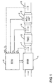
- FIG. 1 shows in highly simplified form an internal combustion engine 1 with an exhaust gas purification system, the exhaust gas cleaning system a three way catalyst (engl TWC -. T hree- W ay C atalyst) and includes a downstream three-way catalyst 2 arranged NO x storage catalytic converter 3 ,
- the three-way catalyst 2 serves to reduce the hydrocarbon and carbon monoxide concentration in the exhaust gas, while the NO x storage catalytic converter 3 has the task to absorb nitrogen oxides from the exhaust gas and to buffer them.
- the exhaust gas purification system has an exhaust gas probe 4, which is arranged between the three-way catalytic converter 2 and the NO x storage catalytic converter 3 and measures the oxygen concentration in the exhaust gas.
- the exhaust gas sensor 4 is (engl ECU. - E lectronic C ontrol U nit) with an electronic engine controller 5 is connected, which controls the internal combustion engine 1 or predetermines the mixture composition of the internal combustion engine 1.
- the emission control system has a temperature sensor 6 which is attached to the NO x storage catalytic converter 3 and indirectly detects the temperature of the NO x storage catalytic converter 3, wherein the temperature sensor 6 is also connected to the electronic engine control 5 on the output side.
- the measurement of the temperature of the NO x storage catalytic converter 3 is necessary since the NO x storage catalytic converter 3 must be heated at regular intervals for sulfur detoxification, whereby a certain minimum temperature must be reached in order to reduce the stored sulfur compounds, which is thus controlled by the electronic engine controller 5 can be.
- the emission control system an exhaust gas probe 7, which in an exhaust passage between the internal combustion engine 1 and the three-way catalyst 2 arranged is and the oxygen concentration in the exhaust gas of Internal combustion engine 1 upstream of the three-way catalyst 2 measures. From the oxygen concentration thus measured, the electronic engine controller 5 then determine whether the oxygen storage capacity of the three-way catalyst 2 exhausted is, as will be described in detail.
- a further exhaust gas probe 8 is additionally arranged downstream of the NO x storage catalytic converter 3, which measures the exhaust gas composition downstream of the NO x storage catalytic converter 3 in order to be able to detect a breakdown of the NO x storage catalytic converter 3.
- a breakdown of the NO x storage catalytic converter 3 occurs when the absolute storage capacity of the NO x storage catalytic converter 3 is exceeded and the nitrogen oxides contained in the exhaust gas of the internal combustion engine 1 can thus no longer be stored in the NO x storage catalytic converter.
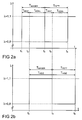
- Figure 2a shows the time profile of the air ratio ⁇ at the entrance of the three-way catalyst 2
- Figure 2b shows the time course of the air ratio ⁇ between the three-way catalyst 2 and the NO x storage catalyst 3 for the same period.
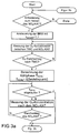
- the heating phase T HEIZ continues only until the storage capacity of the three-way catalyst 2 is exhausted and the previously stored in the three-way catalyst 2 hydrocarbons is exothermally burned.
- the oxygen concentration in the exhaust gas of the internal combustion engine 1 in the exhaust passage between the three-way catalyst 2 and the NO x storage catalyst 3 is continuously measured by the exhaust gas probe 4 in order to detect an oxygen breakdown of the three-way catalyst 2.
- the superstoichiometric operating phase T MAGER with a lean mixture of the internal combustion engine 1 is still maintained for a predetermined cooling phase T COOL , in order to cool the three-way catalyst 2.
- T COOL also the storage of oxygen in the three-way catalyst 2.
- the duration of the cooling phase T COOL is hereby read in dependence on the current operating point of the internal combustion engine 1 from a map.
- Such a premature termination of the superstoichiometric operating phase T MAGER at a breakdown of the NO x storage catalyst 3 is useful, since the NO x storage catalyst 3 is not further heated in a continuation of the superstoichiometric operation after an oxygen breakdown.
- This heating of the three-way catalyst 2 is caused by the fact that the previously stored oxygen reacts exothermically with the excess fuel.
- fuel is stored in the three-way catalyst 2, which is burned exothermic during the next heating phase T HEIZ .
- the oxygen concentration between the three-way catalytic converter 2 and the NO x storage catalytic converter 3 is continuously measured by the exhaust gas probe 4 in order to be able to detect a breakdown of the three-way catalytic converter 2.
- the substoichiometric operating phase T FAT is then ended.
- the substoichiometric operating phase T FETT is also terminated when the NO x storage catalyst 3 strikes through during the substoichiometric operating phase T FAT .
- This premature termination of the stoichiometric operating phase T FAT in the event of a breakdown of the NO x storage catalytic converter 3 makes sense, since the NO x storage catalytic converter 3 is not further heated after a breakdown due to an exhaustion of its storage capacity.
- the substoichiometric operating phase T FET of the NO x storage catalytic converter 3 also begins only at the time t 4 in the event of a breakdown of the three-way catalytic converter 2.
Landscapes
- Engineering & Computer Science (AREA)
- Chemical & Material Sciences (AREA)
- Combustion & Propulsion (AREA)
- Mechanical Engineering (AREA)
- General Engineering & Computer Science (AREA)
- Exhaust Gas After Treatment (AREA)
Applications Claiming Priority (2)
| Application Number | Priority Date | Filing Date | Title |
|---|---|---|---|
| DE10318210A DE10318210B4 (de) | 2003-04-22 | 2003-04-22 | Betriebsverfahren für eine Brennkraftmaschine mit einem Vorkatalysator und einem Speicherkatalysator |
| DE10318210 | 2003-04-22 |
Publications (2)
| Publication Number | Publication Date |
|---|---|
| EP1471237A2 true EP1471237A2 (fr) | 2004-10-27 |
| EP1471237A3 EP1471237A3 (fr) | 2010-11-03 |
Family
ID=32946394
Family Applications (1)
| Application Number | Title | Priority Date | Filing Date |
|---|---|---|---|
| EP03029000A Withdrawn EP1471237A3 (fr) | 2003-04-22 | 2003-12-17 | Méthode d'opération pour un moteur à combustion avec catalyseur et pré-catalyseur |
Country Status (2)
| Country | Link |
|---|---|
| EP (1) | EP1471237A3 (fr) |
| DE (1) | DE10318210B4 (fr) |
Cited By (1)
| Publication number | Priority date | Publication date | Assignee | Title |
|---|---|---|---|---|
| GB2467245A (en) * | 2005-05-02 | 2010-07-28 | Cummins Inc | Method for regenerating an exhaust gas aftertreatment component using oxygen concentration |
Families Citing this family (1)
| Publication number | Priority date | Publication date | Assignee | Title |
|---|---|---|---|---|
| DE102005032941A1 (de) * | 2005-07-14 | 2007-01-18 | Siemens Ag | Verfahren und Vorrichtung zur Desulfatisierung eines NOx-Speicherkatalysators |
Family Cites Families (12)
| Publication number | Priority date | Publication date | Assignee | Title |
|---|---|---|---|---|
| JP2778383B2 (ja) * | 1992-10-02 | 1998-07-23 | 日産自動車株式会社 | エンジンの空燃比制御装置 |
| EP0625633B1 (fr) * | 1992-12-03 | 2000-03-15 | Toyota Jidosha Kabushiki Kaisha | Epurateur de gaz d'echappement pour moteurs a combustion interne |
| WO2000060229A1 (fr) * | 1999-04-06 | 2000-10-12 | Mitsubishi Jidosha Kogyo Kabushiki Kaisha | Dispositif anti-pollution pour moteurs thermiques |
| DE19923498A1 (de) * | 1999-05-21 | 2000-11-23 | Volkswagen Ag | Verfahren zur Steuerung einer Regeneration eines NOx-Speicherkatalysators |
| DE19926149A1 (de) * | 1999-06-09 | 2000-12-14 | Volkswagen Ag | Verfahren zur Erfassung einer Schädigung von wenigsens einem in einem Abgaskanal einer Verbrennungskraftmaschine angeordneten NO¶x¶-Speicherkatalysator |
| DE19926146A1 (de) * | 1999-06-09 | 2000-12-14 | Volkswagen Ag | Verfahren zur Initiierung und Überwachung einer Entschwefelung von wenigstens einem in einem Abgaskanal einer Verbrennungskraftmaschine angeordneten NOx-Speicherkatalysator |
| JP2001050086A (ja) * | 1999-08-09 | 2001-02-23 | Denso Corp | 内燃機関の空燃比制御装置 |
| DE10008564A1 (de) * | 2000-01-19 | 2002-05-02 | Volkswagen Ag | Verfahren und Vorrichtung zur Steuerung der Regeneration eines NOx-Speicherkatalysators |
| DE10036390B4 (de) * | 2000-07-26 | 2010-05-12 | Volkswagen Ag | Verfahren und Vorrichtung zur Entschwefelung eines NOx-Speicherkatalysators |
| EP1182340B1 (fr) * | 2000-08-22 | 2005-06-08 | Mazda Motor Corporation | Système de purification de gaz d'échappement pour un moteur à combustion interne |
| DE10057936A1 (de) * | 2000-11-22 | 2002-05-23 | Volkswagen Ag | Verfahren und Vorrichtung zur Regeneration eines NOx-Speicherkatalysators |
| DE10057938A1 (de) * | 2000-11-22 | 2002-05-23 | Volkswagen Ag | Verfahren und Vorrichtung zur Regeneration eines NOx-Speicherkatalysators |
-
2003
- 2003-04-22 DE DE10318210A patent/DE10318210B4/de not_active Expired - Fee Related
- 2003-12-17 EP EP03029000A patent/EP1471237A3/fr not_active Withdrawn
Cited By (2)
| Publication number | Priority date | Publication date | Assignee | Title |
|---|---|---|---|---|
| GB2467245A (en) * | 2005-05-02 | 2010-07-28 | Cummins Inc | Method for regenerating an exhaust gas aftertreatment component using oxygen concentration |
| GB2467245B (en) * | 2005-05-02 | 2010-12-22 | Cummins Inc | Apparatus and method for regenerating an exhaust gas aftertreatment component of an internal combustion engine |
Also Published As
| Publication number | Publication date |
|---|---|
| EP1471237A3 (fr) | 2010-11-03 |
| DE10318210B4 (de) | 2006-06-14 |
| DE10318210A1 (de) | 2004-11-25 |
Similar Documents
| Publication | Publication Date | Title |
|---|---|---|
| EP0892158B1 (fr) | Procédé et dispositif de surveillance de désulfuration de catalyseurs de stockage de NOx | |
| DE19731624A1 (de) | Verfahren und Vorrichtung zur Überwachung der De-Sulfatierung bei NOx-Speicherkatalysatoren | |
| DE102016209566A1 (de) | Steuern einer Stickoxidemission im Abgas einer Brennkraftmaschine | |
| DE10027347B4 (de) | Abgasemissionssteuerungs/regelungsvorrichtung für einen Verbrennungsmotor | |
| EP1193376B1 (fr) | Commande d'un catalyseur accumulateur de nox | |
| EP1192343B1 (fr) | PROCEDE PERMETTANT DE LANCER ET DE SURVEILLER LA DESULFURATION D'AU MOINS UN CATALYSEUR A STOCKAGE DE NOx PLACE DANS UN TUYAU D'ECHAPPEMENT D'UN MOTEUR A COMBUSTION INTERNE | |
| EP1117916B1 (fr) | PROCEDE DE REGENERATION D'UN CATALYSEUR A ACCUMULATION DE NOx D'UN MOTEUR A COMBUSTION INTERNE | |
| DE102015215365A1 (de) | Verfahren zur Regeneration von Abgasnachbehandlungskomponenten eines Verbrennungsmotors sowie Abgasnachbehandlungsvorrichtung für einen Verbrennungsmotor | |
| DE10160704B4 (de) | Verfahren zum Betrieb von Abgasreinigungsvorrichtungen | |
| EP1422410B1 (fr) | Procédé de gestion du fonctionnement d'un moteur à combustion interne multi-cylindres avec catalysateur d'accumulation de nox | |
| DE10114456A1 (de) | Vorrichtung und Verfahren zur Koordination von abgasrelevanten Maßnahmen | |
| DE10226873B4 (de) | Verfahren zur Steuerung der Betriebsartenwahl einer Verbrennungskraftmaschine | |
| EP1204815B1 (fr) | Procede de reglage de la temperature des gaz d'echappement d'un moteur a combustion interne a melange pauvre pendant une desulfuration d'un catalyseur | |
| EP1179124B1 (fr) | Procede de desulfuration | |
| DE10318210B4 (de) | Betriebsverfahren für eine Brennkraftmaschine mit einem Vorkatalysator und einem Speicherkatalysator | |
| DE10026762A1 (de) | Verfahren zur Desulfatisierung eines NOx-Speicher-Katalysators | |
| EP2148049A1 (fr) | Procédé de désulfuration d'un catalyseur de stockage de NOX | |
| DE10330367A1 (de) | Verfahren und Vorrichtung zur Entschwefelung eines Katalysators | |
| DE10153901A1 (de) | Verfahren und Vorrichtung zur Entschwefelung eines einem Dieselmotor nachgeschalteten NOx-Speicherkatalysators | |
| EP1303690B1 (fr) | Procede d'adaptation d'une gamme de temperature de consigne de catalyseur pour un catalyseur a accumulateur de no x? | |
| DE10318214B4 (de) | Verfahren zur Ermittlung des Alterungszustandes eines Speicherkatalysators | |
| EP1252420B1 (fr) | Dispositif et procede de commande d'une regeneration de nox d'un catalyseur accumulateur de nox | |
| EP1471222B1 (fr) | Procédé de régénération d'un catalyseur de stockage pour moteur à combustion interne | |
| DE10112938A1 (de) | Verfahren zur Steuerung eines Warmlaufs eines Katalysatorsystems | |
| EP1188915B1 (fr) | Procédé de réglage de la régénération d'un catalyseur d'accumulation de NOx |
Legal Events
| Date | Code | Title | Description |
|---|---|---|---|
| PUAI | Public reference made under article 153(3) epc to a published international application that has entered the european phase |
Free format text: ORIGINAL CODE: 0009012 |
|
| AK | Designated contracting states |
Kind code of ref document: A2 Designated state(s): AT BE BG CH CY CZ DE DK EE ES FI FR GB GR HU IE IT LI LU MC NL PT RO SE SI SK TR |
|
| AX | Request for extension of the european patent |
Extension state: AL LT LV MK |
|
| RAP1 | Party data changed (applicant data changed or rights of an application transferred) |
Owner name: DAIMLERCHRYSLER AG Owner name: SIEMENS AKTIENGESELLSCHAFT |
|
| RAP1 | Party data changed (applicant data changed or rights of an application transferred) |
Owner name: DAIMLER AG Owner name: SIEMENS AKTIENGESELLSCHAFT |
|
| RAP1 | Party data changed (applicant data changed or rights of an application transferred) |
Owner name: DAIMLER AG Owner name: CONTINENTAL AUTOMOTIVE GMBH |
|
| PUAL | Search report despatched |
Free format text: ORIGINAL CODE: 0009013 |
|
| AK | Designated contracting states |
Kind code of ref document: A3 Designated state(s): AT BE BG CH CY CZ DE DK EE ES FI FR GB GR HU IE IT LI LU MC NL PT RO SE SI SK TR |
|
| AX | Request for extension of the european patent |
Extension state: AL LT LV MK |
|
| RIC1 | Information provided on ipc code assigned before grant |
Ipc: F02D 41/30 20060101ALI20100928BHEP Ipc: F02D 41/02 20060101ALI20100928BHEP Ipc: F02D 41/14 20060101AFI20040802BHEP |
|
| REG | Reference to a national code |
Ref country code: DE Ref legal event code: R108 |
|
| AKY | No designation fees paid | ||
| REG | Reference to a national code |
Ref country code: DE Ref legal event code: R108 Effective date: 20110701 |
|
| STAA | Information on the status of an ep patent application or granted ep patent |
Free format text: STATUS: THE APPLICATION IS DEEMED TO BE WITHDRAWN |
|
| 18D | Application deemed to be withdrawn |
Effective date: 20110504 |