EP1469366A2 - Robinet pour installation de chauffage - Google Patents
Robinet pour installation de chauffage Download PDFInfo
- Publication number
- EP1469366A2 EP1469366A2 EP04002639A EP04002639A EP1469366A2 EP 1469366 A2 EP1469366 A2 EP 1469366A2 EP 04002639 A EP04002639 A EP 04002639A EP 04002639 A EP04002639 A EP 04002639A EP 1469366 A2 EP1469366 A2 EP 1469366A2
- Authority
- EP
- European Patent Office
- Prior art keywords
- valve
- temperature sensor
- valve according
- room temperature
- abutment
- Prior art date
- Legal status (The legal status is an assumption and is not a legal conclusion. Google has not performed a legal analysis and makes no representation as to the accuracy of the status listed.)
- Granted
Links
Images


Classifications
-
- G—PHYSICS
- G05—CONTROLLING; REGULATING
- G05D—SYSTEMS FOR CONTROLLING OR REGULATING NON-ELECTRIC VARIABLES
- G05D23/00—Control of temperature
- G05D23/01—Control of temperature without auxiliary power
- G05D23/02—Control of temperature without auxiliary power with sensing element expanding and contracting in response to changes of temperature
- G05D23/021—Control of temperature without auxiliary power with sensing element expanding and contracting in response to changes of temperature the sensing element being a non-metallic solid, e.g. elastomer, paste
- G05D23/023—Control of temperature without auxiliary power with sensing element expanding and contracting in response to changes of temperature the sensing element being a non-metallic solid, e.g. elastomer, paste the sensing element being placed outside a regulating fluid flow
Definitions
- the invention relates to a valve according to the preamble of Claim 1.
- a valve of the known type (DE 202 03 735 U1) with a combination sensor head already enables an independent Setting the room temperature sensor and return temperature sensor.
- the return temperature sensor is replaced by a Set collar during assembly to a specified one for the regulated Heating circuit compatible water temperature set.
- the collar is often no longer for a user easily accessible and for adjusting the return temperature not suitable by a user.
- the room temperature is only at the room temperature sensor changed.
- Such a valve has the disadvantage that the adjustable room temperature range is restricted. For example can with extreme weather conditions, where the Room temperature sensor set to the highest temperature level the corresponding room temperature is not reached because the return temperature is too low.
- the invention is based, to operate a task Valve with combi sensor head to improve and its area of application to enlarge.
- the return temperature can be reduced by one using the adjusting sleeve User can be set easily. Thereby the adjustable temperature range of the valve increases and the room temperature may be faster to reach.
- the adjustment sleeve can make the adjustment easier Notes and setting signs.
- the adjustment of the room temperature sensor with that of the return temperature sensor be coupled.
- Such a coupling can be achieved by a fixed connection Adjustment elements are achieved, with different Adjusting strokes through different thread pitches of the sensor adjustment elements is made possible in a simple manner.
- valve be designed to be pivotable or different connecting pieces have so that it is in different mounting positions can be used.
- appropriate connectors can be used with such a valve also several heating circuits regulate at the same time.
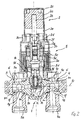
- a valve for regulating heating systems has one Combination sensor head on which a room temperature sensor 2 and a return temperature sensor 3 in a coaxial arrangement includes.
- the combination sensor head is on a valve housing 1 attached, which swivels on one side in an inlet connector 4 and on the other side in an outlet connector 5 is included.
- At the inlet connector 4 can two heating circuits in inlet holes 4a and connected to the outlet connector 5 in outlet bores 5a become.
- the room temperature sensor 2 essentially in one around its Longitudinal axis rotatable adjustment cap 2c and the return temperature sensor 3 in a rotatable adjusting sleeve 3d accommodated.
- the room temperature sensor 2 is general known type and therefore not shown in detail here. It has an expansion body 2a, which is a pressure member 2b acted upon.
- the room temperature sensor 2 is on its adjusting cap 2c provided on a counter thread 2e Thread 2d screwed on the return temperature sensor 3.
- the return temperature sensor 3 also has an expansion body 3a, which extends coaxially to the pressure member 2b and is supported on an abutment 3b, which by means of a Threaded connection 3e is held in an adjusting ring 3c.
- the Abutment 3b is prevented from rotating.
- the outer circumference the adjusting ring 3c is connected to the adjusting sleeve 3d. A Rotation of the adjusting sleeve 3d therefore leads to a shift of the Abutment 3b and the expansion body 3a supported thereon in the direction of the axis of rotation of the adjusting sleeve 3d.
- the abutment 3b is penetrated by a slotted transmission element 2g, at one end the pressure member 2b via a Compensating spring 2f attacks.
- the other end of the transmission link 2g is supported on the expansion body 3a.
- the combination sensor head is by means of a threaded ring 3f on a connection piece 1d of the valve housing 1 attached.
- valve stem 1b which carries a valve plate 1a.
- the valve stem 1b is received in a stuffing box 1h, which is screwed into the valve housing 1 and a valve chamber 1i closes.
- the valve stem 1b and the valve plate 1a are with a return spring 1e against the blocking direction of the valve biased.
- the stuffing box is 1h screwed a heat-conducting element 1k, which the expansion body 3a partially encloses. In this way, the temperature of the through a through hole 1g supplied or removed heating fluid transferred to the expansion body 3a.
- the return temperature of the heating fluid can twist the adjustment sleeve 3d can be adjusted.
- the rotation of the Adjusting ring 3c causes a displacement of the abutment 3b, see above that the valve plate 1a in one direction over the Valve stem 1b adjacent expansion body 3a or in the opposite direction is shifted by the return spring 1e. If the Heating fluid exceeds the set value, expands the expansion body 3a extends and closes the valve. While the cooling of the expansion body 3a becomes the valve stem 1b by the return spring 1e against the expansion body 3a held so that the valve opens again.
- a second embodiment of the Valve is the adjustment cap 2c 'of the room temperature sensor 2' in one piece with the adjustment sleeve 3d 'of the return temperature sensor 3 'executed, so that only one rotation can be done.
- the adjustment cap 2c ' is like the first Embodiment rotatably held by a thread 2d in that it engages with a counter thread 2e.
- the thread 2d is on a support ring 2h supported on the adjusting ring 3c ' intended.
- the adjusting sleeve 3d takes the adjusting ring as it rotates 3c 'with, so that the abutment 3b over the threaded connection 3e can be adjusted in the axial direction.
- the measure of Adjustment depends on the thread pitch, so that a different size adjustment of pressure member 2b and Expansion body 3a can be selected. Otherwise it corresponds 3 that of the embodiment in FIG. 2 and will not be described again here.
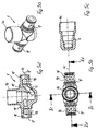
- 4a to 4c is the valve housing 1 with the connecting pieces 4 and 5 in different pivot positions of the Connection piece 1a shown.
- the position of the connector 1a in FIG. 4a corresponds to the representations in FIG. 1 and 2.
- the axes of rotation of room temperature sensor 2 and return temperature sensor 3 and the axes of the inlet and outlet bores 4a and 5a lie in one plane.
- the heating fluid for example through the inlet bore 4a, flows through the valve housing 1 approximately horizontally Direction and emerges from the outlet bore 5a, whereby through the through holes 1g into the valve housing 1 exit.
- the through holes 1f are through the Connections 4 and 5 closed.
- the valve housing 1 shown in Fig. 4b is opposite Connection pieces 4 and 5 by 90 ° from the drawing level pivoted. In this position the through holes are aligned 1f with the inlet and outlet bores 4a and 5a. The Through holes 1g are through the connecting pieces 4 and 5 locked. When the valve housing 1 rotates around the Pivot axis 1c by 180 ° are all, as shown in Fig. 4c Through holes 1f and 1g closed. In this position can, for example, do assembly work on the heating system be made without the heating water completely must be drained.
- the storage of the valve housing 1 in the inlet and outlet fittings 4 and 5 are designed as rotary unions 6.
- the rotary unions 6 are, as in FIGS. 5a to 5d can be seen by two concentric to the swivel axis 1c extending ring grooves 11 formed in the sealing rings 1m are inserted.
- With completely transverse to the pivot axis 1c through-holes 1f leading through the valve housing 1 can have two inlet bores facing each other at the same time 4a and outlet bores 5a connected Heating circuits can be controlled with the valve.
Landscapes
- Physics & Mathematics (AREA)
- Fluid Mechanics (AREA)
- General Physics & Mathematics (AREA)
- Engineering & Computer Science (AREA)
- Automation & Control Theory (AREA)
- Temperature-Responsive Valves (AREA)
- Details Of Valves (AREA)
- Indication Of The Valve Opening Or Closing Status (AREA)
- Heat-Pump Type And Storage Water Heaters (AREA)
Applications Claiming Priority (2)
| Application Number | Priority Date | Filing Date | Title |
|---|---|---|---|
| DE10307359 | 2003-02-21 | ||
| DE10307359A DE10307359B3 (de) | 2003-02-21 | 2003-02-21 | Ventil für Heizungsanlagen |
Publications (3)
| Publication Number | Publication Date |
|---|---|
| EP1469366A2 true EP1469366A2 (fr) | 2004-10-20 |
| EP1469366A3 EP1469366A3 (fr) | 2005-06-15 |
| EP1469366B1 EP1469366B1 (fr) | 2006-11-29 |
Family
ID=32695224
Family Applications (1)
| Application Number | Title | Priority Date | Filing Date |
|---|---|---|---|
| EP04002639A Expired - Lifetime EP1469366B1 (fr) | 2003-02-21 | 2004-02-06 | Robinet pour installation de chauffage |
Country Status (4)
| Country | Link |
|---|---|
| EP (1) | EP1469366B1 (fr) |
| AT (1) | ATE347130T1 (fr) |
| DE (2) | DE10307359B3 (fr) |
| DK (1) | DK1469366T3 (fr) |
Cited By (2)
| Publication number | Priority date | Publication date | Assignee | Title |
|---|---|---|---|---|
| EP1703357A1 (fr) * | 2005-03-14 | 2006-09-20 | Gampper Technik GmbH | Agencement de vannes pour un radiateur d'une installation de chauffage à eau chaude |
| CN102606799A (zh) * | 2010-12-17 | 2012-07-25 | 丹佛斯公司 | 阀装置和操作阀的方法 |
Families Citing this family (1)
| Publication number | Priority date | Publication date | Assignee | Title |
|---|---|---|---|---|
| DE202011051835U1 (de) * | 2011-11-02 | 2013-02-04 | U.S.H.-Innovationen Gmbh | Gehäuseformling für ein Heizungsventil |
Citations (1)
| Publication number | Priority date | Publication date | Assignee | Title |
|---|---|---|---|---|
| DE20203735U1 (de) | 2002-03-07 | 2003-07-24 | U.S.H. Innovationen GmbH, 33758 Schloß Holte-Stukenbrock | Kombiventil für Heizungsanlagen |
Family Cites Families (2)
| Publication number | Priority date | Publication date | Assignee | Title |
|---|---|---|---|---|
| GB1152381A (en) * | 1966-05-24 | 1969-05-14 | Dole Valve Co | Improvements in or relating to Fluid Flow Control Valves |
| DE29805473U1 (de) * | 1998-03-25 | 1998-06-10 | U.S.H. Fittings + Kunststoffteile GmbH, 33689 Bielefeld | Rücklauftemperaturbegrenzer |
-
2003
- 2003-02-21 DE DE10307359A patent/DE10307359B3/de not_active Expired - Fee Related
-
2004
- 2004-02-06 EP EP04002639A patent/EP1469366B1/fr not_active Expired - Lifetime
- 2004-02-06 DK DK04002639T patent/DK1469366T3/da active
- 2004-02-06 DE DE502004002136T patent/DE502004002136D1/de not_active Expired - Lifetime
- 2004-02-06 AT AT04002639T patent/ATE347130T1/de active
Patent Citations (1)
| Publication number | Priority date | Publication date | Assignee | Title |
|---|---|---|---|---|
| DE20203735U1 (de) | 2002-03-07 | 2003-07-24 | U.S.H. Innovationen GmbH, 33758 Schloß Holte-Stukenbrock | Kombiventil für Heizungsanlagen |
Cited By (3)
| Publication number | Priority date | Publication date | Assignee | Title |
|---|---|---|---|---|
| EP1703357A1 (fr) * | 2005-03-14 | 2006-09-20 | Gampper Technik GmbH | Agencement de vannes pour un radiateur d'une installation de chauffage à eau chaude |
| CN102606799A (zh) * | 2010-12-17 | 2012-07-25 | 丹佛斯公司 | 阀装置和操作阀的方法 |
| CN102606799B (zh) * | 2010-12-17 | 2016-08-10 | 丹佛斯公司 | 阀装置和操作阀的方法 |
Also Published As
| Publication number | Publication date |
|---|---|
| DE10307359B3 (de) | 2004-08-12 |
| ATE347130T1 (de) | 2006-12-15 |
| EP1469366A3 (fr) | 2005-06-15 |
| EP1469366B1 (fr) | 2006-11-29 |
| DK1469366T3 (da) | 2007-04-02 |
| DE502004002136D1 (de) | 2007-01-11 |
Similar Documents
| Publication | Publication Date | Title |
|---|---|---|
| DE69929615T2 (de) | Abgedichtete kupplung mit verstellbarer geometrie | |
| EP0918655B1 (fr) | Dispositif d'accouplement pour un vehicule | |
| DE2709386C2 (de) | Drosselrückschlagventil | |
| EP0838625B1 (fr) | Dispositif de raccordement pour la connexion de deux éléments de tuyaux | |
| EP2781664B1 (fr) | Robinetterie sanitaire avec tuyauterie intérieure | |
| DE202014101342U1 (de) | Roboterarm und Montageset | |
| DE112004000164B4 (de) | Pneumatisch angetriebenes Motorwerkzeug mit verstellbarem Auslaßdeflektor für die Abluft | |
| EP3252359B1 (fr) | Soupape à tiroir rotatif | |
| DE4421387B4 (de) | Einlochmischbatterie | |
| EP1610043B1 (fr) | Valve de fluid | |
| EP2183509A2 (fr) | Dispositif de restriction de la section transversale libre d'une conduite de vapeur ou analogue | |
| EP3141666A1 (fr) | Robinetterie, en particulier pour caravane, camping-car ou bateau | |
| EP1469366A2 (fr) | Robinet pour installation de chauffage | |
| EP0269666B1 (fr) | Systeme de fixation | |
| DE102009044995A1 (de) | Schneidwerkzeug mit austauschbarem Schneideinsatz | |
| DE202023100218U1 (de) | Schaltvorrichtung für kryogene Fluide und Mehrfachfilteranordnung für kryogene Fluide | |
| DE2414701A1 (de) | Handsteuereinrichtung zum orientieren der scheinwerfer eines fahrzeuges | |
| DE10049231A1 (de) | Anordnung zur Verbindung von Fluidleitungen | |
| DE4432822C2 (de) | Adapterstück | |
| DE102017114724B4 (de) | Verteilervorrichtung für ein Rohrleitungssystem | |
| EP0663253B1 (fr) | Dispositif de serrage pour machine-outil avec un verin de serrage rotatif | |
| DE8807784U1 (de) | Aufweitwerkzeug | |
| DE2634721A1 (de) | Hydraulisches dreiwegeventil, insbesondere wasseranschluss fuer mund- und/ oder hautmassage- bzw. hautreinigungsduschen | |
| CH695506A5 (de) | Rammgerät. | |
| EP1614944A1 (fr) | Vanne à voies multiples ou vanne de distribution |
Legal Events
| Date | Code | Title | Description |
|---|---|---|---|
| PUAI | Public reference made under article 153(3) epc to a published international application that has entered the european phase |
Free format text: ORIGINAL CODE: 0009012 |
|
| AK | Designated contracting states |
Kind code of ref document: A2 Designated state(s): AT BE BG CH CY CZ DE DK EE ES FI FR GB GR HU IE IT LI LU MC NL PT RO SE SI SK TR |
|
| AX | Request for extension of the european patent |
Extension state: AL LT LV MK |
|
| PUAL | Search report despatched |
Free format text: ORIGINAL CODE: 0009013 |
|
| AK | Designated contracting states |
Kind code of ref document: A3 Designated state(s): AT BE BG CH CY CZ DE DK EE ES FI FR GB GR HU IE IT LI LU MC NL PT RO SE SI SK TR |
|
| AX | Request for extension of the european patent |
Extension state: AL LT LV MK |
|
| 17P | Request for examination filed |
Effective date: 20051102 |
|
| AKX | Designation fees paid |
Designated state(s): AT BE BG CH CY CZ DE DK EE ES FI FR GB GR HU IE IT LI LU MC NL PT RO SE SI SK TR |
|
| GRAP | Despatch of communication of intention to grant a patent |
Free format text: ORIGINAL CODE: EPIDOSNIGR1 |
|
| GRAS | Grant fee paid |
Free format text: ORIGINAL CODE: EPIDOSNIGR3 |
|
| GRAA | (expected) grant |
Free format text: ORIGINAL CODE: 0009210 |
|
| AK | Designated contracting states |
Kind code of ref document: B1 Designated state(s): AT BE BG CH CY CZ DE DK EE ES FI FR GB GR HU IE IT LI LU MC NL PT RO SE SI SK TR |
|
| PG25 | Lapsed in a contracting state [announced via postgrant information from national office to epo] |
Ref country code: IT Free format text: LAPSE BECAUSE OF FAILURE TO SUBMIT A TRANSLATION OF THE DESCRIPTION OR TO PAY THE FEE WITHIN THE PRESCRIBED TIME-LIMIT;WARNING: LAPSES OF ITALIAN PATENTS WITH EFFECTIVE DATE BEFORE 2007 MAY HAVE OCCURRED AT ANY TIME BEFORE 2007. THE CORRECT EFFECTIVE DATE MAY BE DIFFERENT FROM THE ONE RECORDED. Effective date: 20061129 Ref country code: IE Free format text: LAPSE BECAUSE OF FAILURE TO SUBMIT A TRANSLATION OF THE DESCRIPTION OR TO PAY THE FEE WITHIN THE PRESCRIBED TIME-LIMIT Effective date: 20061129 Ref country code: CZ Free format text: LAPSE BECAUSE OF FAILURE TO SUBMIT A TRANSLATION OF THE DESCRIPTION OR TO PAY THE FEE WITHIN THE PRESCRIBED TIME-LIMIT Effective date: 20061129 Ref country code: SK Free format text: LAPSE BECAUSE OF FAILURE TO SUBMIT A TRANSLATION OF THE DESCRIPTION OR TO PAY THE FEE WITHIN THE PRESCRIBED TIME-LIMIT Effective date: 20061129 Ref country code: FI Free format text: LAPSE BECAUSE OF FAILURE TO SUBMIT A TRANSLATION OF THE DESCRIPTION OR TO PAY THE FEE WITHIN THE PRESCRIBED TIME-LIMIT Effective date: 20061129 Ref country code: SI Free format text: LAPSE BECAUSE OF FAILURE TO SUBMIT A TRANSLATION OF THE DESCRIPTION OR TO PAY THE FEE WITHIN THE PRESCRIBED TIME-LIMIT Effective date: 20061129 Ref country code: RO Free format text: LAPSE BECAUSE OF FAILURE TO SUBMIT A TRANSLATION OF THE DESCRIPTION OR TO PAY THE FEE WITHIN THE PRESCRIBED TIME-LIMIT Effective date: 20061129 |
|
| REG | Reference to a national code |
Ref country code: GB Ref legal event code: FG4D Free format text: NOT ENGLISH |
|
| REG | Reference to a national code |
Ref country code: CH Ref legal event code: EP |
|
| REG | Reference to a national code |
Ref country code: IE Ref legal event code: FG4D Free format text: LANGUAGE OF EP DOCUMENT: GERMAN |
|
| REF | Corresponds to: |
Ref document number: 502004002136 Country of ref document: DE Date of ref document: 20070111 Kind code of ref document: P |
|
| REG | Reference to a national code |
Ref country code: SE Ref legal event code: TRGR |
|
| PG25 | Lapsed in a contracting state [announced via postgrant information from national office to epo] |
Ref country code: BG Free format text: LAPSE BECAUSE OF FAILURE TO SUBMIT A TRANSLATION OF THE DESCRIPTION OR TO PAY THE FEE WITHIN THE PRESCRIBED TIME-LIMIT Effective date: 20070228 Ref country code: MC Free format text: LAPSE BECAUSE OF NON-PAYMENT OF DUE FEES Effective date: 20070228 |
|
| PG25 | Lapsed in a contracting state [announced via postgrant information from national office to epo] |
Ref country code: ES Free format text: LAPSE BECAUSE OF FAILURE TO SUBMIT A TRANSLATION OF THE DESCRIPTION OR TO PAY THE FEE WITHIN THE PRESCRIBED TIME-LIMIT Effective date: 20070312 |
|
| GBT | Gb: translation of ep patent filed (gb section 77(6)(a)/1977) |
Effective date: 20070305 |
|
| REG | Reference to a national code |
Ref country code: DK Ref legal event code: T3 |
|
| PG25 | Lapsed in a contracting state [announced via postgrant information from national office to epo] |
Ref country code: PT Free format text: LAPSE BECAUSE OF FAILURE TO SUBMIT A TRANSLATION OF THE DESCRIPTION OR TO PAY THE FEE WITHIN THE PRESCRIBED TIME-LIMIT Effective date: 20070430 |
|
| ET | Fr: translation filed | ||
| REG | Reference to a national code |
Ref country code: IE Ref legal event code: FD4D |
|
| PLBE | No opposition filed within time limit |
Free format text: ORIGINAL CODE: 0009261 |
|
| STAA | Information on the status of an ep patent application or granted ep patent |
Free format text: STATUS: NO OPPOSITION FILED WITHIN TIME LIMIT |
|
| 26N | No opposition filed |
Effective date: 20070830 |
|
| PG25 | Lapsed in a contracting state [announced via postgrant information from national office to epo] |
Ref country code: GR Free format text: LAPSE BECAUSE OF FAILURE TO SUBMIT A TRANSLATION OF THE DESCRIPTION OR TO PAY THE FEE WITHIN THE PRESCRIBED TIME-LIMIT Effective date: 20070301 |
|
| PGFP | Annual fee paid to national office [announced via postgrant information from national office to epo] |
Ref country code: DK Payment date: 20080215 Year of fee payment: 5 |
|
| PGFP | Annual fee paid to national office [announced via postgrant information from national office to epo] |
Ref country code: GB Payment date: 20080206 Year of fee payment: 5 Ref country code: SE Payment date: 20080218 Year of fee payment: 5 |
|
| PGFP | Annual fee paid to national office [announced via postgrant information from national office to epo] |
Ref country code: FR Payment date: 20080131 Year of fee payment: 5 |
|
| REG | Reference to a national code |
Ref country code: CH Ref legal event code: PL |
|
| PG25 | Lapsed in a contracting state [announced via postgrant information from national office to epo] |
Ref country code: LI Free format text: LAPSE BECAUSE OF NON-PAYMENT OF DUE FEES Effective date: 20080229 Ref country code: CH Free format text: LAPSE BECAUSE OF NON-PAYMENT OF DUE FEES Effective date: 20080229 |
|
| PG25 | Lapsed in a contracting state [announced via postgrant information from national office to epo] |
Ref country code: EE Free format text: LAPSE BECAUSE OF FAILURE TO SUBMIT A TRANSLATION OF THE DESCRIPTION OR TO PAY THE FEE WITHIN THE PRESCRIBED TIME-LIMIT Effective date: 20061129 |
|
| PG25 | Lapsed in a contracting state [announced via postgrant information from national office to epo] |
Ref country code: CY Free format text: LAPSE BECAUSE OF FAILURE TO SUBMIT A TRANSLATION OF THE DESCRIPTION OR TO PAY THE FEE WITHIN THE PRESCRIBED TIME-LIMIT Effective date: 20061129 Ref country code: LU Free format text: LAPSE BECAUSE OF NON-PAYMENT OF DUE FEES Effective date: 20070206 |
|
| PG25 | Lapsed in a contracting state [announced via postgrant information from national office to epo] |
Ref country code: TR Free format text: LAPSE BECAUSE OF FAILURE TO SUBMIT A TRANSLATION OF THE DESCRIPTION OR TO PAY THE FEE WITHIN THE PRESCRIBED TIME-LIMIT Effective date: 20061129 Ref country code: HU Free format text: LAPSE BECAUSE OF FAILURE TO SUBMIT A TRANSLATION OF THE DESCRIPTION OR TO PAY THE FEE WITHIN THE PRESCRIBED TIME-LIMIT Effective date: 20070530 |
|
| EUG | Se: european patent has lapsed | ||
| REG | Reference to a national code |
Ref country code: DK Ref legal event code: EBP |
|
| GBPC | Gb: european patent ceased through non-payment of renewal fee |
Effective date: 20090206 |
|
| REG | Reference to a national code |
Ref country code: FR Ref legal event code: ST Effective date: 20091030 |
|
| PG25 | Lapsed in a contracting state [announced via postgrant information from national office to epo] |
Ref country code: FR Free format text: LAPSE BECAUSE OF NON-PAYMENT OF DUE FEES Effective date: 20090302 Ref country code: GB Free format text: LAPSE BECAUSE OF NON-PAYMENT OF DUE FEES Effective date: 20090206 |
|
| PG25 | Lapsed in a contracting state [announced via postgrant information from national office to epo] |
Ref country code: DK Free format text: LAPSE BECAUSE OF NON-PAYMENT OF DUE FEES Effective date: 20090831 |
|
| PGFP | Annual fee paid to national office [announced via postgrant information from national office to epo] |
Ref country code: BE Payment date: 20100329 Year of fee payment: 7 Ref country code: NL Payment date: 20100228 Year of fee payment: 7 |
|
| PG25 | Lapsed in a contracting state [announced via postgrant information from national office to epo] |
Ref country code: SE Free format text: LAPSE BECAUSE OF NON-PAYMENT OF DUE FEES Effective date: 20090207 |
|
| BERE | Be: lapsed |
Owner name: U.S.H.-INNOVATIONEN G.M.B.H. Effective date: 20110228 |
|
| REG | Reference to a national code |
Ref country code: NL Ref legal event code: V1 Effective date: 20110901 |
|
| PG25 | Lapsed in a contracting state [announced via postgrant information from national office to epo] |
Ref country code: BE Free format text: LAPSE BECAUSE OF NON-PAYMENT OF DUE FEES Effective date: 20110228 |
|
| PG25 | Lapsed in a contracting state [announced via postgrant information from national office to epo] |
Ref country code: NL Free format text: LAPSE BECAUSE OF NON-PAYMENT OF DUE FEES Effective date: 20110901 |
|
| PGFP | Annual fee paid to national office [announced via postgrant information from national office to epo] |
Ref country code: AT Payment date: 20130228 Year of fee payment: 10 |
|
| REG | Reference to a national code |
Ref country code: AT Ref legal event code: MM01 Ref document number: 347130 Country of ref document: AT Kind code of ref document: T Effective date: 20140206 |
|
| PG25 | Lapsed in a contracting state [announced via postgrant information from national office to epo] |
Ref country code: AT Free format text: LAPSE BECAUSE OF NON-PAYMENT OF DUE FEES Effective date: 20140206 |
|
| PGFP | Annual fee paid to national office [announced via postgrant information from national office to epo] |
Ref country code: DE Payment date: 20150216 Year of fee payment: 12 |
|
| REG | Reference to a national code |
Ref country code: DE Ref legal event code: R119 Ref document number: 502004002136 Country of ref document: DE |
|
| PG25 | Lapsed in a contracting state [announced via postgrant information from national office to epo] |
Ref country code: DE Free format text: LAPSE BECAUSE OF NON-PAYMENT OF DUE FEES Effective date: 20160901 |