EP1469205B1 - Kraftelement - Google Patents
Kraftelement Download PDFInfo
- Publication number
- EP1469205B1 EP1469205B1 EP04008316A EP04008316A EP1469205B1 EP 1469205 B1 EP1469205 B1 EP 1469205B1 EP 04008316 A EP04008316 A EP 04008316A EP 04008316 A EP04008316 A EP 04008316A EP 1469205 B1 EP1469205 B1 EP 1469205B1
- Authority
- EP
- European Patent Office
- Prior art keywords
- piston
- cylinder sleeve
- plunger
- force element
- accordance
- Prior art date
- Legal status (The legal status is an assumption and is not a legal conclusion. Google has not performed a legal analysis and makes no representation as to the accuracy of the status listed.)
- Expired - Lifetime
Links
- 230000007704 transition Effects 0.000 claims description 6
- 238000007789 sealing Methods 0.000 claims description 3
- 239000007789 gas Substances 0.000 claims description 2
- 239000002184 metal Substances 0.000 claims description 2
- 238000007373 indentation Methods 0.000 claims 1
- 238000009434 installation Methods 0.000 description 2
- 230000006978 adaptation Effects 0.000 description 1
- 238000004519 manufacturing process Methods 0.000 description 1
- 238000000034 method Methods 0.000 description 1
Images

Classifications
-
- F—MECHANICAL ENGINEERING; LIGHTING; HEATING; WEAPONS; BLASTING
- F15—FLUID-PRESSURE ACTUATORS; HYDRAULICS OR PNEUMATICS IN GENERAL
- F15B—SYSTEMS ACTING BY MEANS OF FLUIDS IN GENERAL; FLUID-PRESSURE ACTUATORS, e.g. SERVOMOTORS; DETAILS OF FLUID-PRESSURE SYSTEMS, NOT OTHERWISE PROVIDED FOR
- F15B15/00—Fluid-actuated devices for displacing a member from one position to another; Gearing associated therewith
- F15B15/19—Pyrotechnical actuators
Definitions
- the invention relates to a force element according to the preamble of claim 1 ( EP-A-0731004 ).
- Power elements are used to initiate, trigger or directly actuate mechanical control operations.
- a piston on which a plunger is arranged moves, which then extends out of the housing the plunger and thus can initiate a mechanical movement process by exerting force.
- power elements of this design are complicated and expensive. Especially in the automotive security sector requires solutions with high technical performance at low price.
- the invention is based on the object to improve a force element according to the preamble of claim 1 so that it is more stable.
- the piston has a larger diameter than the plunger and both are interconnected via an annular shoulder.
- the cylinder sleeve is adapted to this and has a larger diameter in the region of the piston than in the region of the plunger.
- the transition of the cylinder sleeve from the larger to the smaller diameter in the extended state of the plunger serves as a stop for the annular shoulder of the piston.
- the cylinder sleeve is made of a metal.
- a preferably semicircular bulge is introduced in the piston on the end facing the drive element.
- the wall of the cylinder sleeve is advantageously bent outwards, so that the cylinder sleeve is better anchored in the surrounding housing.
- a sealing ring is embedded on the outer circumference of the piston.
- the plunger is anchored after the ignition of the drive element in its driven position, the plunger is preferably formed at its end facing away from the piston conical, so that it passes when expelled in a press fit with the cylinder sleeve.
- the housing is made of plastic.
- a method for producing a force element according to the invention is characterized in that the cylinder sleeve, the drive element and the piston are manufactured individually with the plunger and then mounted closed as a kit and is finally surrounded by the plastic housing.
- mechanical control problems can be solved as a modular system that can be adapted to a wide variety of tasks.
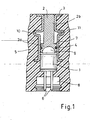
- the three functional elements of the force element according to the invention as pyrotechnic drive element 1 (see Figure 1), plunger 2 with integrated piston 2a and sealing ring 4 and the cylinder sleeve 3 are manufactured individually and then mounted as a kit closed and after a variety of customer installation conditions with a plastic housing 5 (see Also Fig. 2) surrounded.
- This modular system has the advantage that the actual functional unit consisting of drive element 1, plunger 2 with piston 2a and cylinder sleeve 3 can be adapted without restriction with an outer shape of the housing for a variety of installation conditions.
- FIG. 2 shows various embodiments of the outer adaptation geometry with a very wide variety of housings 5.
- an electrical tripping current pulse is applied to the connector pins 6 of the drive element 1 via a sensor system.
- the pyrotechnic drive charge is ignited in the drive element 1, whereby a drive pressure in the region of the piston 2 a arises, which expels the plunger 2 via the piston 2 a.
- the formed by the transition of the piston 2a to the plunger 2 annular shoulder 7 can strike in its final position to the cylinder sleeve 3 and thus be slowed down.
- the plunger 2 may also be slightly conical, so that it passes during expulsion by the conicity in a press fit with the cylinder sleeve 3.
- a plug receptacle is designated with Verrastungsform, via which the plug to the pins 6 of the drive element 1 can be fastened.
- the cylinder sleeve 3 is formed open at its end faces, wherein on one end side, the drive element 1 is inserted and on the other end of the Plunger 2 is arranged or protruding.
- the plunger 2 has on the side facing the drive element 1 a piston 2a, which has a larger diameter than the plunger 2 and is connected thereto via an annular shoulder 7.
- the cylinder sleeve 3 which has a larger diameter in the region of the piston 2a and the drive element 1 than at the end of the cylinder sleeve 3 opposite the drive element 1.
- the transition 10 of the cylinder sleeve 3 from the larger to the smaller diameter is used in the extended state of the plunger 2 as a stop 11 for the piston 2a.
- a semicircular bulge 9 is introduced in the piston 2a.
- Figure 2 shows various housing 5 of the force element, namely as a quarter-circle in the section, triangular with z.
- B. a dovetail groove 12 for attachment, round or rectangular.
Landscapes
- Engineering & Computer Science (AREA)
- Chemical & Material Sciences (AREA)
- Analytical Chemistry (AREA)
- Physics & Mathematics (AREA)
- Fluid Mechanics (AREA)
- Mechanical Engineering (AREA)
- General Engineering & Computer Science (AREA)
- Actuator (AREA)
- Fluid-Damping Devices (AREA)
- Steering Control In Accordance With Driving Conditions (AREA)
- Devices For Conveying Motion By Means Of Endless Flexible Members (AREA)
Description
- Die Erfindung betrifft ein Kraftelement nach dem Oberbegriff des Anspruchs 1 (
EP-A-0731004 ). - Kraftelemente werden eingesetzt, um mechanische Steuerungsvorgänge in Gang zu setzen, auszulösen oder direkt zu betätigen. Wie auch in der
DE 2 747 977 A1 beschrieben, wird nach Zündung einer pyrotechnischen Ladung eines Anzündelements in einem Gehäuse ein Kolben, auf dem ein Stößel angeordnet ist, bewegt, der dann aus dem Gehäuse den Stößel ausfährt und damit einen mechanischen Bewegungsvorgang durch Ausübung von Kraft einleiten kann. Kraftelemente dieser Bauform sind jedoch aufwendig und kostspielig. Speziell der Einsatz im Automobilsicherheitsbereich erfordert Lösungen mit hoher technischer Performance bei niedrigem Preis. - Der Erfindung liegt die Aufgabe zu Grunde, ein Kraftelement nach dem Oberbegriff des Anspruchs 1 so zu verbessern, dass dieses stabiler ist.
- Diese Aufgabe wird erfindungsgemäß dadurch die Merkmale des Anspruch 1 gelöst.
- Der Kolben weist einen größeren Durchmesser als der Stößel auf und beide sind über einen ringförmigen Absatz miteinander verbunden. Die Zylinderhülse ist hieran angepasst und weist im Bereich des Kolbens einen größeren Durchmesser als im Bereich des Stößels auf.
- In vorteilhafter Ausführungsform dient der Übergang der Zylinderhülse vom größeren auf den kleineren Durchmesser im ausgefahrenen Zustand des Stößels als Anschlag für den ringförmigen Absatz des Kolbens.
- Dieser Absatz bzw. Übergang der Zylinderhülse vom größeren auf den kleineren Durchmesser ist durch Stauchen und/oder Falten der Zylinderhülse bzw. deren Wand hergestellt.
- Bevorzugt ist die Zylinderhülse aus einem Metall hergestellt.
- Zum besseren Druckaufbau der Antriebsgase ist im Kolben am zum Antriebselement gewandten Ende eine vorzugsweise halbkreisförmige Ausbuchtung eingebracht.
- An den Stirnseiten der Zylinderhülse ist die Wand der Zylinderhülse vorteilhafterweise nach außen umgebogen, so dass die Zylinderhülse besser im umgebenden Gehäuse verankert ist.
- In bevorzugter Ausführungsform ist auf dem Außenumfang des Kolbens ein Dichtungsring eingelassen.
- Damit der Stößel nach der Zündung des Antriebselements in seiner ausgetriebenen Stellung verankert ist, ist bevorzugt der Stößel an seinem dem Kolben abgewandten Ende konisch ausgebildet, so dass er beim Austreiben in einen Presssitz mit der Zylinderhülse übergeht.
- In bevorzugter Ausführungsform besteht das Gehäuse aus Kunststoff.
- Ein Verfahren zur Herstellung eines erfindungsgemäßen Kraftelements zeichnet sich dadurch aus, dass die Zylinderhülse, das Antriebselement und der Kolben mit dem Stößel einzeln gefertigt und anschließend als Bausatz geschlossen montiert werden und zuletzt vom Gehäuse aus Kunststoff umgeben wird.
- Nachfolgend wird die Erfindung an Hand von Figuren genauer erläutert.
- In vorteilhafter Weise lassen sich mechanische Steuerungsprobleme als modulares, den verschiedensten Aufgabenstellungen anpaßbares System lösen. Dazu werden die drei Funktionselemente des erfindungsgemäßen Kraftelements wie pyrotechnisches Antriebselement 1 (siehe Figur 1), Stößel 2 mit integriertem Kolben 2a und Dichtring 4 sowie die Zylinderhülse 3 einzeln gefertigt und dann als Bausatz geschlossen montiert und nach unterschiedlichsten kundenspezifischen Einbauverhältnissen mit einem Kunststoffgehäuse 5 (siehe auch Fig. 2) umgeben.
- Dieses erfindungsgemäße modulare System hat den Vorteil, dass die eigentliche Funktionseinheit bestehend aus Antriebselement 1, Stößel 2 mit Kolben 2a und Zylinderhülse 3 uneingeschränkt mit einer äußeren Formgebung des Gehäuses für die verschiedensten Einbaubedingungen angepaßt werden kann. Figur 2 zeigt verschiedene Ausführungsformen der äußeren Adaptionsgeometrie mit den unterschiedlichsten Gehäusen 5.
- Tritt zum Beispiel an einer elektrischen Einrichtung eine technische Überlastsituation oder im Fahrzeug eine Crashsituation auf, so wird über eine Sensorik ein elektrischer Auslöse- Stromimpuls auf die Anschlußsteckerpins 6 des Antriebselements 1 gegeben. Mit diesem Stromstoß wird die pyrotechnische Antriebsladung im Antriebselement 1 gezündet, wodurch ein Antriebsdruck im Bereich des Kolbens 2a entsteht, der den Stößel 2 über den Kolben 2a austreibt. Der durch den Übergang des Kolbens 2a zum Stößel 2 gebildete ringförmige Absatz 7 kann in seiner Endlage an die Zylinderhülse 3 anschlagen und damit abgebremst werden. Der Stößel 2 kann jedoch auch leicht konisch ausgebildet sein, so dass er beim Austreiben durch die Konizität in einen Preßsitz mit der Zylinderhülse 3 übergeht. Damit wäre der Stößel 2 sehr fest in der Endlage fixiert. Ebenfalls kann diese Konizität ein gesteuertes Abbremsen ermöglichen. Mit dem Bezugszeichen 8 ist eine Steckeraufnahme mit Verrastungsform bezeichnet, über die der Stecker an die Pins 6 des Antriebselements 1 befestigbar ist.
- Die Zylinderhülse 3 ist an ihren Stirnseiten offen ausgebildet, wobei auf einer Stirnseite das Antriebselement 1 eingeschoben ist und auf der anderen Stirnseite der Stößel 2 angeordnet ist oder herausragt. Der Stößel 2 weist an der zum Antriebselement 1 zeigenden Seite einen Kolben 2a auf, der einen größeren Durchmesser als der Stößel 2 aufweist und mit diesem über einen ringförmigen Absatz 7 verbunden ist. Hieran angepasst ist die Zylinderhülse 3, die im Bereich des Kolbens 2a und des Antriebselements 1 einen größeren Durchmesser als an dem dem Antriebselement 1 entgegengesetzten Ende der Zylinderhülse 3 aufweist. Der Übergang 10 der Zylinderhülse 3 vom größeren auf den kleineren Durchmesser dient im ausgefahrenen Zustand des Stößels 2 als Anschlag 11 für den Kolben 2a. An dem zum Antriebselement 1 gewandten Ende des Kolbens 2a ist im Kolben 2a eine halbkreisförmige Ausbuchtung 9 eingebracht.
- Figur 2 zeigt verschiedene Gehäuse 5 des Kraftelements, nämlich als im Schnitt viertelkreisförmig, dreieckig mit z. B. einer Schwalbenschwanznut 12 zur Befestigung, rund oder rechteckig.
Claims (9)
- Kraftelement mit einer an ihren Stirnseiten offenen Zylinderhülse (3) in der ein gaserzeugendes Antriebselement (1) und ein Kolben (2a) mit einem auf dem Kolben (2a) angeordneten Stößel (2) angeordnet sind, wobei der Kolben (2a) von den erzeugten Antriebsgasen des Antriebselementes (1) in Austrittsrichtung des Stößels (2) aus der Zylinderhülse (3) beschleunigbar ist, wobei an einer ersten Stirnseite der Zylinderhülse (3) das Antriebselement (1) eingeschoben ist und an einer zweiten Stirnseite der Stößel (2) angeordnet ist, dadurch gekennzeichnet, dass sich des Kraftelement in einem Gehäuse (5) befindet, und dass an den Stirnseiten die Wand der Zylinderhülse (3) rechtwinklig nach außen umgebogen ist.
- Kraftelement, nach Anspruch 1, dadurch gekennzeichnet, dass der Kolben (2a) einen größeren Durchmesser als der Stößel (2) aufweist und beide über einen ringförmigen Absatz (7) miteinander verbunden sind, wobei die Zylinderhülse (3) im Bereich des Kolbens (2a) einen größeren Durchmesser als im Bereich des Stößels (2) aufweist.
- Kraftelement nach Anspruch 2, dadurch gekennzeichnet, dass der Übergang (10) der Zylinderhülse (3) vom größeren auf den kleineren Durchmesser im ausgefahrenen Zustand des Stößels (2) als Anschlag (11) für den ringförmigen Absatz (7) des Kolbens (2a) dient.
- Kraftelement nach Anspruch 2 oder 3, dadurch gekennzeichnet, dass der Übergang (10) der Zylinderhülse (3) vom größeren auf den kleineren Durchmesser durch Stauchen und/oder Falten der Zylinderhülse (3) hergestellt ist.
- Kraftelement nach einem der Ansprüche 1 bis 4, dadurch gekennzeichnet, dass die Zylinderhülse (3) aus einem Metall besteht.
- Kraftelement nach einem der Ansprüche 1 bis 5, dadurch gekennzeichnet, dass im Kolben (2a) am zum Antriebselement (1) gewandten Ende eine vorzugsweise halbkreisförmige Ausbuchtung (9) eingebracht ist.
- Kraftelement nach einem der Ansprüche 1 bis 6, dadurch gekennzeichnet, dass auf dem Außenumfang des Kolbens (2a) ein Dichtungsring (4) eingelassen ist.
- Kraftelement nach einem der Ansprüche 1 bis 7, dadurch gekennzeichnet, dass der Stößel (2) an seinem dem Kolben (2a) abgewandten Ende konisch ausgebildet ist.
- Kraftelement nach einem der Ansprüche 1 bis 8, dadurch gekennzeichnet, dass das Gehäuse (5) aus Kunststoff besteht.
Applications Claiming Priority (4)
| Application Number | Priority Date | Filing Date | Title |
|---|---|---|---|
| DE10317987 | 2003-04-19 | ||
| DE10317987 | 2003-04-19 | ||
| DE102004009444 | 2004-02-27 | ||
| DE102004009444A DE102004009444A1 (de) | 2003-04-19 | 2004-02-27 | Kraftelement |
Publications (3)
| Publication Number | Publication Date |
|---|---|
| EP1469205A2 EP1469205A2 (de) | 2004-10-20 |
| EP1469205A3 EP1469205A3 (de) | 2005-05-11 |
| EP1469205B1 true EP1469205B1 (de) | 2007-08-15 |
Family
ID=32909561
Family Applications (1)
| Application Number | Title | Priority Date | Filing Date |
|---|---|---|---|
| EP04008316A Expired - Lifetime EP1469205B1 (de) | 2003-04-19 | 2004-04-06 | Kraftelement |
Country Status (3)
| Country | Link |
|---|---|
| EP (1) | EP1469205B1 (de) |
| AT (1) | ATE370336T1 (de) |
| DE (1) | DE502004004612D1 (de) |
Families Citing this family (4)
| Publication number | Priority date | Publication date | Assignee | Title |
|---|---|---|---|---|
| US8635872B2 (en) | 2007-09-14 | 2014-01-28 | Ruag Ammotec Gmbh | Pyrotechnical actuator |
| FR2966431B1 (fr) * | 2010-10-22 | 2012-12-21 | Dassault Aviat | Actionneur pneumatique d'ejection d'un emport porte par un aeronef et procede d'ejection associe |
| AT12531U1 (de) * | 2011-05-23 | 2012-07-15 | Hirtenberger Automotive Safety Gmbh & Co Kg | Pyrotechnischer aktuator |
| AT511500B1 (de) * | 2011-05-23 | 2013-02-15 | Hirtenberger Automotive Safety Gmbh & Co Kg | Pyrotechnischer Aktuator |
Family Cites Families (4)
| Publication number | Priority date | Publication date | Assignee | Title |
|---|---|---|---|---|
| DE2747977C2 (de) * | 1977-10-26 | 1986-06-19 | Dynamit Nobel Ag, 5210 Troisdorf | Elektrisch auslösbares Kraftelement mit ausstoßendem Kolben |
| FR2731398B1 (fr) * | 1995-03-10 | 1997-05-30 | Ecia Equip Composants Ind Auto | Actionneur a declenchement pilote de manoeuvre d'un organe, par exemple de vehicule automobile |
| DE60111319T2 (de) * | 2000-08-04 | 2006-03-23 | Automotive Systems Laboratory Inc., Farmington Hills | Pyrotechnischer Aktuator |
| DE10203710C1 (de) * | 2002-01-31 | 2003-02-13 | Thomas Magnete Gmbh | Pyrotechnischer Aktor |
-
2004
- 2004-04-06 EP EP04008316A patent/EP1469205B1/de not_active Expired - Lifetime
- 2004-04-06 AT AT04008316T patent/ATE370336T1/de not_active IP Right Cessation
- 2004-04-06 DE DE502004004612T patent/DE502004004612D1/de not_active Expired - Lifetime
Also Published As
| Publication number | Publication date |
|---|---|
| DE502004004612D1 (de) | 2007-09-27 |
| EP1469205A3 (de) | 2005-05-11 |
| ATE370336T1 (de) | 2007-09-15 |
| EP1469205A2 (de) | 2004-10-20 |
Similar Documents
| Publication | Publication Date | Title |
|---|---|---|
| EP2545575B1 (de) | Sicherung für kraftfahrzeugenergieleitung | |
| EP1960731B1 (de) | Pyrotechnische aktuatoreinheit, verfahren zu deren herstellung sowie gassackmodul mit einer solchen aktuatoreinheit | |
| EP2136088B1 (de) | Verbindungselement mit einer Schraube und einer daran unverlierbar angeordneten Hülse | |
| EP2040339B1 (de) | Steckverbinder mit Lamellenkontakt für Glühkerze | |
| EP0882302B1 (de) | Stromunterbrecher für eine batterieleitung von fahrzeugen | |
| EP1443296B1 (de) | Pyromechanisches Trennelement | |
| EP0715993A2 (de) | Hybrid-Gasgenerator für Sicherheitssysteme in Kraftfahrzeugen | |
| EP0782945A1 (de) | Gasgenerator für ein Fahrzeug-Rückhaltesystem | |
| DE112020001016T5 (de) | Projektil-Anordnung und Elektro-Kreis-Unterbrecher-Vorrichtung | |
| WO1997031406A1 (de) | Batterie-kabelklemme für fahrzeuge | |
| EP2203648B1 (de) | Pyrotechnisches kraftelement | |
| DE102007014403A1 (de) | Pyrotechnische Antriebseinheit sowie Verfahren zur Herstellung einer solchen Antriebseinheit | |
| EP1469205B1 (de) | Kraftelement | |
| EP2740874B1 (de) | Verfahren und anordnung zum verschliessen einer öffnung in einem körper, insbesondere in einem türbetätiger | |
| EP2235395B1 (de) | Abschlusskappe für ein antriebskabel, antriebskabel, verfahren zur herstellung einer abschlusskappe sowie verfahren zur herstellung eines antriebskabels | |
| DE102004009444A1 (de) | Kraftelement | |
| WO2022248382A1 (de) | Mikrogasgenerator und verfahren zur herstellung eines mikrogasgenerators | |
| DE102008005983B4 (de) | Abschlußkappe für ein Antriebskabel, Antriebskabel, Verfahren zur Herstellung einer Abschlußkappe sowie Verfahren zur Herstellung eines Antriebskabels | |
| EP1207086B1 (de) | Airbagbaueinheit | |
| WO2021122142A1 (de) | Gasgenerator insbesondere für ein fahrzeugsicherheitssystem | |
| AT526223B1 (de) | Pyrotechnischer Aktuator | |
| EP1160534B1 (de) | Zündvorrichtung für ein Sicherheitssystem | |
| DE102004035712B4 (de) | Baugruppe mit Gasgenerator, Verfahren zur Herstellung der Baugruppe und Umformwerkzeug zur Verwendung in dem Verfahren | |
| DE102013210889A1 (de) | Verbindungseinrichtung | |
| DE202012009270U1 (de) | Betätigungseinrichtung |
Legal Events
| Date | Code | Title | Description |
|---|---|---|---|
| PUAI | Public reference made under article 153(3) epc to a published international application that has entered the european phase |
Free format text: ORIGINAL CODE: 0009012 |
|
| AK | Designated contracting states |
Kind code of ref document: A2 Designated state(s): AT BE BG CH CY CZ DE DK EE ES FI FR GB GR HU IE IT LI LU MC NL PL PT RO SE SI SK TR |
|
| AX | Request for extension of the european patent |
Extension state: AL HR LT LV MK |
|
| RAP1 | Party data changed (applicant data changed or rights of an application transferred) |
Owner name: DELPHI TECHNOLOGIES, INC. |
|
| PUAL | Search report despatched |
Free format text: ORIGINAL CODE: 0009013 |
|
| AK | Designated contracting states |
Kind code of ref document: A3 Designated state(s): AT BE BG CH CY CZ DE DK EE ES FI FR GB GR HU IE IT LI LU MC NL PL PT RO SE SI SK TR |
|
| AX | Request for extension of the european patent |
Extension state: AL HR LT LV MK |
|
| AKX | Designation fees paid | ||
| 17P | Request for examination filed |
Effective date: 20060111 |
|
| RBV | Designated contracting states (corrected) |
Designated state(s): AT BE BG CH CY CZ DE DK EE ES FI FR GB GR HU IE IT LI LU MC NL PL PT RO SE SI SK TR |
|
| GRAP | Despatch of communication of intention to grant a patent |
Free format text: ORIGINAL CODE: EPIDOSNIGR1 |
|
| GRAS | Grant fee paid |
Free format text: ORIGINAL CODE: EPIDOSNIGR3 |
|
| GRAA | (expected) grant |
Free format text: ORIGINAL CODE: 0009210 |
|
| AK | Designated contracting states |
Kind code of ref document: B1 Designated state(s): AT BE BG CH CY CZ DE DK EE ES FI FR GB GR HU IE IT LI LU MC NL PL PT RO SE SI SK TR |
|
| REG | Reference to a national code |
Ref country code: GB Ref legal event code: FG4D Free format text: NOT ENGLISH |
|
| REG | Reference to a national code |
Ref country code: CH Ref legal event code: EP |
|
| REG | Reference to a national code |
Ref country code: IE Ref legal event code: FG4D Free format text: LANGUAGE OF EP DOCUMENT: GERMAN |
|
| REF | Corresponds to: |
Ref document number: 502004004612 Country of ref document: DE Date of ref document: 20070927 Kind code of ref document: P |
|
| ET | Fr: translation filed | ||
| PG25 | Lapsed in a contracting state [announced via postgrant information from national office to epo] |
Ref country code: BG Free format text: LAPSE BECAUSE OF FAILURE TO SUBMIT A TRANSLATION OF THE DESCRIPTION OR TO PAY THE FEE WITHIN THE PRESCRIBED TIME-LIMIT Effective date: 20071115 Ref country code: NL Free format text: LAPSE BECAUSE OF FAILURE TO SUBMIT A TRANSLATION OF THE DESCRIPTION OR TO PAY THE FEE WITHIN THE PRESCRIBED TIME-LIMIT Effective date: 20070815 Ref country code: ES Free format text: LAPSE BECAUSE OF FAILURE TO SUBMIT A TRANSLATION OF THE DESCRIPTION OR TO PAY THE FEE WITHIN THE PRESCRIBED TIME-LIMIT Effective date: 20071126 Ref country code: FI Free format text: LAPSE BECAUSE OF FAILURE TO SUBMIT A TRANSLATION OF THE DESCRIPTION OR TO PAY THE FEE WITHIN THE PRESCRIBED TIME-LIMIT Effective date: 20070815 |
|
| NLV1 | Nl: lapsed or annulled due to failure to fulfill the requirements of art. 29p and 29m of the patents act | ||
| PG25 | Lapsed in a contracting state [announced via postgrant information from national office to epo] |
Ref country code: PL Free format text: LAPSE BECAUSE OF FAILURE TO SUBMIT A TRANSLATION OF THE DESCRIPTION OR TO PAY THE FEE WITHIN THE PRESCRIBED TIME-LIMIT Effective date: 20070815 |
|
| GBV | Gb: ep patent (uk) treated as always having been void in accordance with gb section 77(7)/1977 [no translation filed] |
Effective date: 20070815 |
|
| REG | Reference to a national code |
Ref country code: IE Ref legal event code: FD4D |
|
| PG25 | Lapsed in a contracting state [announced via postgrant information from national office to epo] |
Ref country code: GR Free format text: LAPSE BECAUSE OF FAILURE TO SUBMIT A TRANSLATION OF THE DESCRIPTION OR TO PAY THE FEE WITHIN THE PRESCRIBED TIME-LIMIT Effective date: 20071116 |
|
| PG25 | Lapsed in a contracting state [announced via postgrant information from national office to epo] |
Ref country code: IE Free format text: LAPSE BECAUSE OF FAILURE TO SUBMIT A TRANSLATION OF THE DESCRIPTION OR TO PAY THE FEE WITHIN THE PRESCRIBED TIME-LIMIT Effective date: 20070815 Ref country code: CZ Free format text: LAPSE BECAUSE OF FAILURE TO SUBMIT A TRANSLATION OF THE DESCRIPTION OR TO PAY THE FEE WITHIN THE PRESCRIBED TIME-LIMIT Effective date: 20070815 Ref country code: GB Free format text: LAPSE BECAUSE OF FAILURE TO SUBMIT A TRANSLATION OF THE DESCRIPTION OR TO PAY THE FEE WITHIN THE PRESCRIBED TIME-LIMIT Effective date: 20070815 Ref country code: PT Free format text: LAPSE BECAUSE OF FAILURE TO SUBMIT A TRANSLATION OF THE DESCRIPTION OR TO PAY THE FEE WITHIN THE PRESCRIBED TIME-LIMIT Effective date: 20080115 Ref country code: SK Free format text: LAPSE BECAUSE OF FAILURE TO SUBMIT A TRANSLATION OF THE DESCRIPTION OR TO PAY THE FEE WITHIN THE PRESCRIBED TIME-LIMIT Effective date: 20070815 |
|
| PLBE | No opposition filed within time limit |
Free format text: ORIGINAL CODE: 0009261 |
|
| STAA | Information on the status of an ep patent application or granted ep patent |
Free format text: STATUS: NO OPPOSITION FILED WITHIN TIME LIMIT |
|
| PG25 | Lapsed in a contracting state [announced via postgrant information from national office to epo] |
Ref country code: RO Free format text: LAPSE BECAUSE OF FAILURE TO SUBMIT A TRANSLATION OF THE DESCRIPTION OR TO PAY THE FEE WITHIN THE PRESCRIBED TIME-LIMIT Effective date: 20070815 Ref country code: SE Free format text: LAPSE BECAUSE OF FAILURE TO SUBMIT A TRANSLATION OF THE DESCRIPTION OR TO PAY THE FEE WITHIN THE PRESCRIBED TIME-LIMIT Effective date: 20071115 |
|
| 26N | No opposition filed |
Effective date: 20080516 |
|
| BERE | Be: lapsed |
Owner name: DELPHI TECHNOLOGIES, INC. Effective date: 20080430 |
|
| PG25 | Lapsed in a contracting state [announced via postgrant information from national office to epo] |
Ref country code: MC Free format text: LAPSE BECAUSE OF NON-PAYMENT OF DUE FEES Effective date: 20080430 |
|
| REG | Reference to a national code |
Ref country code: CH Ref legal event code: PL |
|
| PG25 | Lapsed in a contracting state [announced via postgrant information from national office to epo] |
Ref country code: EE Free format text: LAPSE BECAUSE OF FAILURE TO SUBMIT A TRANSLATION OF THE DESCRIPTION OR TO PAY THE FEE WITHIN THE PRESCRIBED TIME-LIMIT Effective date: 20070815 Ref country code: LI Free format text: LAPSE BECAUSE OF NON-PAYMENT OF DUE FEES Effective date: 20080430 Ref country code: CH Free format text: LAPSE BECAUSE OF NON-PAYMENT OF DUE FEES Effective date: 20080430 |
|
| PG25 | Lapsed in a contracting state [announced via postgrant information from national office to epo] |
Ref country code: BE Free format text: LAPSE BECAUSE OF NON-PAYMENT OF DUE FEES Effective date: 20080430 |
|
| PG25 | Lapsed in a contracting state [announced via postgrant information from national office to epo] |
Ref country code: SI Free format text: LAPSE BECAUSE OF FAILURE TO SUBMIT A TRANSLATION OF THE DESCRIPTION OR TO PAY THE FEE WITHIN THE PRESCRIBED TIME-LIMIT Effective date: 20070815 |
|
| PG25 | Lapsed in a contracting state [announced via postgrant information from national office to epo] |
Ref country code: CY Free format text: LAPSE BECAUSE OF FAILURE TO SUBMIT A TRANSLATION OF THE DESCRIPTION OR TO PAY THE FEE WITHIN THE PRESCRIBED TIME-LIMIT Effective date: 20070815 |
|
| PG25 | Lapsed in a contracting state [announced via postgrant information from national office to epo] |
Ref country code: AT Free format text: LAPSE BECAUSE OF NON-PAYMENT OF DUE FEES Effective date: 20080406 |
|
| PG25 | Lapsed in a contracting state [announced via postgrant information from national office to epo] |
Ref country code: DK Free format text: LAPSE BECAUSE OF FAILURE TO SUBMIT A TRANSLATION OF THE DESCRIPTION OR TO PAY THE FEE WITHIN THE PRESCRIBED TIME-LIMIT Effective date: 20070815 |
|
| PG25 | Lapsed in a contracting state [announced via postgrant information from national office to epo] |
Ref country code: HU Free format text: LAPSE BECAUSE OF FAILURE TO SUBMIT A TRANSLATION OF THE DESCRIPTION OR TO PAY THE FEE WITHIN THE PRESCRIBED TIME-LIMIT Effective date: 20080216 Ref country code: LU Free format text: LAPSE BECAUSE OF NON-PAYMENT OF DUE FEES Effective date: 20080406 |
|
| PG25 | Lapsed in a contracting state [announced via postgrant information from national office to epo] |
Ref country code: TR Free format text: LAPSE BECAUSE OF FAILURE TO SUBMIT A TRANSLATION OF THE DESCRIPTION OR TO PAY THE FEE WITHIN THE PRESCRIBED TIME-LIMIT Effective date: 20070815 |
|
| REG | Reference to a national code |
Ref country code: DE Ref legal event code: R082 Ref document number: 502004004612 Country of ref document: DE Representative=s name: BECKER UND KOLLEGEN, DE Ref country code: DE Ref legal event code: R082 Ref document number: 502004004612 Country of ref document: DE Representative=s name: PATENTANWAELTE BECKER & MUELLER, DE |
|
| PGFP | Annual fee paid to national office [announced via postgrant information from national office to epo] |
Ref country code: IT Payment date: 20110415 Year of fee payment: 8 |
|
| REG | Reference to a national code |
Ref country code: FR Ref legal event code: TP Owner name: AUTOLIV DEVELOPMENT AB, SE Effective date: 20120514 |
|
| PG25 | Lapsed in a contracting state [announced via postgrant information from national office to epo] |
Ref country code: IT Free format text: LAPSE BECAUSE OF NON-PAYMENT OF DUE FEES Effective date: 20120406 |
|
| PGFP | Annual fee paid to national office [announced via postgrant information from national office to epo] |
Ref country code: DE Payment date: 20150227 Year of fee payment: 12 |
|
| REG | Reference to a national code |
Ref country code: FR Ref legal event code: PLFP Year of fee payment: 13 |
|
| REG | Reference to a national code |
Ref country code: DE Ref legal event code: R119 Ref document number: 502004004612 Country of ref document: DE |
|
| PG25 | Lapsed in a contracting state [announced via postgrant information from national office to epo] |
Ref country code: DE Free format text: LAPSE BECAUSE OF NON-PAYMENT OF DUE FEES Effective date: 20161101 |
|
| REG | Reference to a national code |
Ref country code: FR Ref legal event code: PLFP Year of fee payment: 14 |
|
| PGFP | Annual fee paid to national office [announced via postgrant information from national office to epo] |
Ref country code: FR Payment date: 20170425 Year of fee payment: 14 |
|
| PG25 | Lapsed in a contracting state [announced via postgrant information from national office to epo] |
Ref country code: FR Free format text: LAPSE BECAUSE OF NON-PAYMENT OF DUE FEES Effective date: 20180430 |