EP1468898B1 - Système d'amortissement des chocs de retour au volant d'un automobile - Google Patents
Système d'amortissement des chocs de retour au volant d'un automobile Download PDFInfo
- Publication number
- EP1468898B1 EP1468898B1 EP04005218A EP04005218A EP1468898B1 EP 1468898 B1 EP1468898 B1 EP 1468898B1 EP 04005218 A EP04005218 A EP 04005218A EP 04005218 A EP04005218 A EP 04005218A EP 1468898 B1 EP1468898 B1 EP 1468898B1
- Authority
- EP
- European Patent Office
- Prior art keywords
- steering
- wheel
- angle
- position angle
- wheel position
- Prior art date
- Legal status (The legal status is an assumption and is not a legal conclusion. Google has not performed a legal analysis and makes no representation as to the accuracy of the status listed.)
- Expired - Lifetime
Links
- 230000035939 shock Effects 0.000 title claims description 18
- 238000013016 damping Methods 0.000 claims abstract description 20
- 238000011156 evaluation Methods 0.000 claims abstract description 14
- 230000010363 phase shift Effects 0.000 claims description 5
- 230000002123 temporal effect Effects 0.000 claims description 4
- 238000010586 diagram Methods 0.000 description 9
- 230000008859 change Effects 0.000 description 3
- 238000010521 absorption reaction Methods 0.000 description 2
- 230000008901 benefit Effects 0.000 description 2
- 230000005540 biological transmission Effects 0.000 description 2
- 230000000694 effects Effects 0.000 description 2
- 230000007274 generation of a signal involved in cell-cell signaling Effects 0.000 description 2
- 238000005259 measurement Methods 0.000 description 2
- 230000004048 modification Effects 0.000 description 2
- 238000012986 modification Methods 0.000 description 2
- 230000009467 reduction Effects 0.000 description 2
- 239000000969 carrier Substances 0.000 description 1
- 238000012937 correction Methods 0.000 description 1
- 230000008878 coupling Effects 0.000 description 1
- 238000010168 coupling process Methods 0.000 description 1
- 238000005859 coupling reaction Methods 0.000 description 1
- 238000001514 detection method Methods 0.000 description 1
- 238000009434 installation Methods 0.000 description 1
- 230000035484 reaction time Effects 0.000 description 1
- 230000004044 response Effects 0.000 description 1
- 230000008054 signal transmission Effects 0.000 description 1
- 238000012360 testing method Methods 0.000 description 1
Images


Classifications
-
- B—PERFORMING OPERATIONS; TRANSPORTING
- B62—LAND VEHICLES FOR TRAVELLING OTHERWISE THAN ON RAILS
- B62D—MOTOR VEHICLES; TRAILERS
- B62D5/00—Power-assisted or power-driven steering
- B62D5/04—Power-assisted or power-driven steering electrical, e.g. using an electric servo-motor connected to, or forming part of, the steering gear
- B62D5/0457—Power-assisted or power-driven steering electrical, e.g. using an electric servo-motor connected to, or forming part of, the steering gear characterised by control features of the drive means as such
- B62D5/046—Controlling the motor
- B62D5/0472—Controlling the motor for damping vibrations
-
- B—PERFORMING OPERATIONS; TRANSPORTING
- B60—VEHICLES IN GENERAL
- B60T—VEHICLE BRAKE CONTROL SYSTEMS OR PARTS THEREOF; BRAKE CONTROL SYSTEMS OR PARTS THEREOF, IN GENERAL; ARRANGEMENT OF BRAKING ELEMENTS ON VEHICLES IN GENERAL; PORTABLE DEVICES FOR PREVENTING UNWANTED MOVEMENT OF VEHICLES; VEHICLE MODIFICATIONS TO FACILITATE COOLING OF BRAKES
- B60T8/00—Arrangements for adjusting wheel-braking force to meet varying vehicular or ground-surface conditions, e.g. limiting or varying distribution of braking force
- B60T8/17—Using electrical or electronic regulation means to control braking
- B60T8/1755—Brake regulation specially adapted to control the stability of the vehicle, e.g. taking into account yaw rate or transverse acceleration in a curve
-
- B—PERFORMING OPERATIONS; TRANSPORTING
- B62—LAND VEHICLES FOR TRAVELLING OTHERWISE THAN ON RAILS
- B62D—MOTOR VEHICLES; TRAILERS
- B62D7/00—Steering linkage; Stub axles or their mountings
- B62D7/22—Arrangements for reducing or eliminating reaction, e.g. vibration, from parts, e.g. wheels, of the steering system
- B62D7/226—Arrangements for reducing or eliminating reaction, e.g. vibration, from parts, e.g. wheels, of the steering system acting on the steering gear
Definitions
- the invention relates to a system for reducing the Lenkradst dividemaschine in a motor vehicle steering.
- a steering damper which allows an active shock absorption by the damping force is adjusted to a very high value during a period corresponding to the shock duration on the occurrence of a shock.
- the appropriate signal generation to increase the damping via special shock sensors, which are arranged on Radnahen steering gear elements.
- shock sensors which are arranged on Radnahen steering gear elements.
- inertial sensors with sensors that are sensitive in the axial direction are used as impact sensors. These enable low-delay steering damper elements for a short period of time, before the impact has affected these steering damper elements. After a shock, the damping is immediately reduced again. The increase in damping is independent of the behavior of the driver.
- a compensation torque is determined as a function of a sensor-detected disturbance torque and represented by switching on the reference variable of the steering torque via the servomotor. On the basis of the phase curve of the input shaft and the output shaft is detected whether there are disturbance torques from the wheel side.
- the invention has the object to raise a technically simpler alternative to the active reduction of Lenkradst maneuvertechnik.
- the system comprises a sensor device for detecting a steering wheel angle, a sensor device for detecting a wheel position angle, and an evaluation device for evaluating the time profile of the detected) angle, which is configured to determine a phase shift between the course of the steering wheel angle and the course of the wheel position and to generate an actuating signal for increasing the damping in the motor vehicle steering system when the wheel position angle is advanced.
- the knowledge is used that in a driving state in which the driver is not currently making an active steering intervention, acting on the steering shocks first in the region near the wheel z. B. become effective on the steering linkage or on the steering gear before they make themselves felt on the steering wheel.
- the sensor-detected phase difference between the steering wheel angle and the wheel position angle indicates whether the forces acting on the steering first emanate from the wheels or first from the steering wheel. If the signals of the wheel position angle accelerate, it is concluded that there is a shock and, accordingly, the generation of a control signal briefly increases the damping in the steering. In the opposite case, the normal damping level can be maintained.
- the steering wheel angle is usually required as an input. If a steering with electromechanical steering assistance is also provided on the vehicle, a variable representing the wheel position angle is required there.
- ESP electronic stability program
- the present invention advantageously uses this information available on the vehicle to determine a possible phase difference between the steering wheel angle and the Rad einswinkel to reduce the Lenkradst Wunschmaschine. In this case, no additional sensors should be fitted to the vehicle. Rather, the already existing sensors are provided with an additional benefit.
- the signals of the sensor devices for the evaluation device which must be available with high precision, can be made available both analogously and digitally.
- the temporal advance of the wheel position angle is detected statistically by a correlation measurement between the two angle courses with respect to the lead time of the wheel position angle from the maximum of the correlation. If the maximum of the correlation coefficient is in the range of a lead time, the attenuation is increased, preferably as long as this state persists.
- the steering for steering assistance to a servo motor with a rotor preferably picks up the angular position of the rotor.
- the rotational speed of the rotor can also be detected and also evaluated in the evaluation device for the actuating signal generation.
- the Rad einswinkel can be detected radnah elsewhere and independently of an electric servo.
- a separate sensor can also be provided for this purpose. This also applies analogously to the case of the steering wheel angle detection, which need not necessarily take place in connection with an electronic stability program.
- the increase of the damping takes place for example via a switchable steering damper, which can be activated and deactivated by the control signal.
- the embodiment shown in the figures shows a steering 1 of a motor vehicle.
- the steering comprises a steering wheel 2, which is mechanically coupled via a steering shaft 3 with a steering gear 4.
- a steering command introduced on the steering wheel 2 is on the steering shaft 3 and the steering gear 4 on a rack. 5 transferred, which in turn is coupled to tie rods 6.
- the tie rods 6 each engage a wheel carrier 7, which supports a vehicle wheel 8.
- the steering 1 further comprises an electric servomotor 9 for steering assistance.
- a torsion sensor 10 for detecting the torque in the steering, in response to which the servo motor 9 is driven, is a torsion sensor 10 in the manner of a torsion bar, which is incorporated into the steering shaft 3.
- a system for reducing the Lenkradstberichtmaschine is provided on the steering.
- This comprises a sensor device 11 for detecting a steering wheel angle ⁇ and a sensor device 12 for detecting a Rad tooswinkels ⁇ .
- These sensor devices 11 and 12 may be formed in a conventional manner.
- the sensor device 11 is integrated into an electronic stability program (ESP).
- ESP electronic stability program
- the wheel position angle ⁇ from a control of the electromechanical steering assistance, d. H. the control of the servomotor 9 tapped.
- the corresponding sensor device 12 is provided on the servo motor 9 and detects the position of a rotor thereof.
- the rotational speed of the rotor can be detected and made available to the system for reducing the Lenkradstberichttechnik.
- the rotor position represents the wheel position angle ⁇ .
- a sensor device 12 arranged in the region of the wheel carriers 7 or the tie rods 6 can be used to detect the wheel position angle ⁇ .
- the system for reducing the Steering wheel bumps further comprises an evaluation device 13, which evaluates the time course of the detected signals or the detected angle.
- the evaluation device 13 is configured to determine a phase shift between the course of the steering wheel angle ⁇ and the course of the wheel position angle ⁇ and to generate an actuating signal s for increasing the damping in the motor vehicle steering when the wheel position angle ⁇ is advanced.
- the change speeds for the steering wheel angle ⁇ and the wheel position angle ⁇ can be evaluated for the generation of the actuating signal s.
- the control signal s is then supplied to a steering damper 14, not shown, of the steering, which is activated or deactivated by this.
- the damping in the steering can be temporarily increased for a shock.
- the attenuation by the control signal can also be influenced quantitatively. The extent of the damping can then be adjusted depending on the lead time of the wheel position angle ⁇ and / or the amplitudes of the wheel position angle ⁇ .
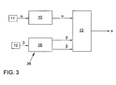
- FIG. 3 shows a block diagram of the system.
- the sensor device 11 transmits the steering wheel angle ⁇ representing signals to a control device 15, in which the electronic stability program (ESP) is implemented.
- the sensor device 12 transmits signals representing the wheel position angle ⁇ in a control device 16 for the electromechanical steering assistance. If appropriate, the corresponding information is then transmitted to the evaluation device 13 in a modified manner in which the actuating signal s is generated in a manner which will be explained in more detail below.
- the signals generated by one or both sensor devices 11 and 12 can also be transmitted directly to the evaluation device 13.
- FIG. 2a shows the case of a driver-side over-regulation, which can occur in very short, pulse-like shocks. Again, a phase shift caused by the impact is observed again, wherein initially the wheel position angle ⁇ leads the steering wheel angle ⁇ .
- the temporal advance of the wheel position angle ⁇ can be determined statistically by a correlation measurement between the two angle courses with respect to the lead time or lag time. For this purpose, the maximum of the correlation is determined. If this is in the range of the lead time for the wheel position angle ⁇ , the damping in the steering is temporarily increased. Otherwise, an increase will not be made.
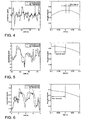
- FIGS. 4 to 6 Now show different states, in each case in the left diagram of the course of the steering wheel link ⁇ and the wheel position angle ⁇ is plotted normalized over time.
- the right diagram represents the associated cross-correlation over time.
- the driver is passive, ie he gives no steering impulse.
- the road bumps move the steering wheel.
- a tracking of the steering wheel angle ⁇ is observed.
- the normalized angular deflections remain smaller than at the wheel side.
- the correlation diagram shows Accordingly, a maximum in the range of the lead time of the Radouswinkels ⁇ . In this case, consequently, the evaluation device 13 will generate a control signal 11 for increasing the damping.
- FIG. 5 shows an active steering intervention by the driver, here are superimposed road bumps.
- the wheel position angle ⁇ follows the steering wheel angle ⁇ , so that the correlation maximum lies in the region of the lag time. In this case, the attenuation is not increased by the evaluation device 13.
- FIG. 6 shows one FIG. 5 corresponding situation in which the driver also actively steers, but the road bumps are significantly lower. In the correlation diagram, this leads to a maximum delay shifted to greater delay, so that here too the evaluation device 13 does not increase the attenuation.
- Another advantage of the invention is that the tuning of the steering with respect to the damping does not have to be carried out over a test track with different ripples and bumps. Rather, the steering adapts to both the road and the steering behavior of the driver.
Landscapes
- Engineering & Computer Science (AREA)
- Transportation (AREA)
- Mechanical Engineering (AREA)
- Chemical & Material Sciences (AREA)
- Combustion & Propulsion (AREA)
- Steering Control In Accordance With Driving Conditions (AREA)
Claims (6)
- Système pour réduire la sensation d'à-coup du volant dans une direction de véhicule automobile, comprenant :- un dispositif de détection (11) pour détecter un angle de volant (α),- un dispositif de détection (12) pour détecter un angle de position des roues (β),- un dispositif d'interprétation (13) pour interpréter la courbe dans le temps des angles (α, β) détectés, lequel est configuré pour déterminer un déphasage entre la courbe de l'angle de volant (α) et la courbe de l'angle de position des roues (β), caractérisé en ce queen présence d'une avance de l'angle de position des roues (β), l'amortissement dans la direction du véhicule automobile (1) est augmenté par le biais d'un signal de commande (s) et
l'avance dans le temps de l'angle de position des roues (β) est détectée statistiquement par une mesure de corrélation entre les deux courbes d'angle en référence au temps d'avance ou au temps de retard, au moyen du maximum de la corrélation. - Système selon la revendication 1, caractérisé en ce que l'angle de volant (α) est prélevé d'un programme de stabilité électrique (ESP).
- Système selon l'une des revendications 1 ou 2, caractérisé en ce que l'angle de position des roues (β) est prélevé d'une commande d'une assistance électromécanique à la direction.
- Système selon l'une des revendications 1 à 3, caractérisé en ce que la direction présente, pour l'assistance à la direction, un servomoteur (9) muni d'un rotor et le dispositif de détection (12) pour détecter l'angle de position des roues (β) détecte la position angulaire du rotor.
- Système selon la revendication 4, caractérisé en ce que la vitesse de rotation du rotor est en plus détectée et interprétée conjointement dans le dispositif d'interprétation (13) pour la génération du signal de commande.
- Système selon l'une des revendications 1 à 5, caractérisé en ce que la direction (1) présente un amortisseur de direction (14) activable qui peut être activé par le signal de commande (s).
Applications Claiming Priority (2)
| Application Number | Priority Date | Filing Date | Title |
|---|---|---|---|
| DE10317991 | 2003-04-19 | ||
| DE10317991A DE10317991A1 (de) | 2003-04-19 | 2003-04-19 | System zur Verminderung der Lenkradstößigkeit bei einer Kraftfahrzeug-Lenkung |
Publications (3)
| Publication Number | Publication Date |
|---|---|
| EP1468898A2 EP1468898A2 (fr) | 2004-10-20 |
| EP1468898A3 EP1468898A3 (fr) | 2006-06-07 |
| EP1468898B1 true EP1468898B1 (fr) | 2011-10-05 |
Family
ID=32892430
Family Applications (1)
| Application Number | Title | Priority Date | Filing Date |
|---|---|---|---|
| EP04005218A Expired - Lifetime EP1468898B1 (fr) | 2003-04-19 | 2004-03-05 | Système d'amortissement des chocs de retour au volant d'un automobile |
Country Status (3)
| Country | Link |
|---|---|
| EP (1) | EP1468898B1 (fr) |
| AT (1) | ATE527158T1 (fr) |
| DE (1) | DE10317991A1 (fr) |
Families Citing this family (14)
| Publication number | Priority date | Publication date | Assignee | Title |
|---|---|---|---|---|
| DE102005003180B4 (de) | 2005-01-19 | 2015-04-02 | Volkswagen Ag | Vorrichtung und Verfahren zur Reduzierung von Fehlanregungen am Lenkrad |
| DE102007026189A1 (de) | 2007-06-05 | 2008-12-11 | Volkswagen Ag | Elektromechanische Lenkung für ein Kraftfahrzeug und Verfahren zum Betrieb einer solchen |
| DE102008026730A1 (de) | 2008-06-04 | 2009-12-17 | Volkswagen Ag | Elektromechanische Lenkung mit Geländemodus |
| DE102008059906B4 (de) | 2008-12-02 | 2015-04-02 | Volkswagen Ag | Elektromechanische Lenkung |
| DE102008061696A1 (de) * | 2008-12-10 | 2010-06-17 | Volkswagen Ag | Elektromechanische Lenkung und Verfahren zur Bestimmung eines Fahrwegzustands |
| DE102009047586A1 (de) * | 2009-12-07 | 2011-06-09 | Zf Lenksysteme Gmbh | Verfahren und Vorrichtung zur Kompensation von Störinformationen in einem elektrischen Lenksystem |
| DE102011052881B4 (de) * | 2011-08-22 | 2018-05-17 | Robert Bosch Automotive Steering Gmbh | Verfahren zur Bestimmung einer Zahnstangenkraft für eine Lenkvorrichtung in einem Fahrzeug, Lenkvorrichtung und Steuer- und/oder Regeleinrichtung für eine Lenkvorrichtung |
| JP2013184622A (ja) | 2012-03-09 | 2013-09-19 | Hitachi Automotive Systems Steering Ltd | 電動パワーステアリング装置及び電動パワーステアリング装置の制御装置 |
| DE102014218686A1 (de) * | 2014-09-17 | 2016-03-17 | Continental Automotive Gmbh | Verfahren zur Kompensation von Hinderniseinflüssen bei einer Lenkvorrichtung, Lenkungssteuervorrichtung, Lenkvorrichtung und Speichermedium |
| GB2541664A (en) * | 2015-08-24 | 2017-03-01 | Jaguar Land Rover Ltd | Dampening lateral vehicle disturbances |
| US9738309B2 (en) * | 2015-11-30 | 2017-08-22 | Steering Solutions Ip Holding Corporation | Active-damping based approach to mitigate effects of rack disturbances on EPS systems |
| CN113184050B (zh) * | 2021-05-31 | 2022-12-09 | 重庆长安汽车股份有限公司 | 一种车辆方向盘摆振的补偿方法及补偿系统 |
| DE102023202152A1 (de) * | 2023-03-10 | 2024-09-12 | Robert Bosch Gesellschaft mit beschränkter Haftung | Vorrichtung und Verfahren zum Dämpfen einer Lenkbewegung bei einem aktiven Lenksystem eines Fahrzeugs, die Vorrichtung umfassendes Fahrzeug |
| DE102023128596A1 (de) * | 2023-10-18 | 2025-04-24 | Cariad Se | Verfahren zum Betreiben eines Lenksystems zum Feststellen von fahrbahnunebenheitsinduzierten Störungen |
Family Cites Families (14)
| Publication number | Priority date | Publication date | Assignee | Title |
|---|---|---|---|---|
| JPH0662092B2 (ja) * | 1986-04-11 | 1994-08-17 | 本田技研工業株式会社 | 電動式パワ−ステアリング装置 |
| DE3724070A1 (de) * | 1987-07-21 | 1989-02-02 | Teves Gmbh Alfred | Verfahren und vorrichtung zum rangieren eines fahrzeuges |
| EP0350819B1 (fr) * | 1988-07-11 | 1993-12-29 | Koyo Seiko Co., Ltd. | Appareil détecteur du point milieu de l'angle de rotation du volant |
| US5141069A (en) * | 1988-09-13 | 1992-08-25 | Aisin Seiki Kabushiki Kaisha | Steering mechanism with toe-in control |
| DE3929177A1 (de) * | 1989-09-02 | 1991-03-07 | Bosch Gmbh Robert | Verfahren zur beeinflussung der daempfung einer servolenkung |
| GB2245873B (en) * | 1990-04-18 | 1994-03-16 | Nissan Motor | Control system for optimizing operation of vehicle performance/safety enhancing systems |
| US5333700A (en) * | 1991-08-26 | 1994-08-02 | Fuji Jukogyo Kabushiki Kaisha | Steering system for a motor vehicle |
| US5596252A (en) * | 1993-12-06 | 1997-01-21 | Honda Giken Kogyo Kabushiki Kaisha | Electrically operated power steering apparatus for assisting manual steering operation in a motor vehicle |
| JPH0811728A (ja) * | 1994-06-29 | 1996-01-16 | Nippon Seiko Kk | 電動式パワーステアリング装置 |
| DE4446123C2 (de) * | 1994-12-22 | 2003-05-22 | Man Nutzfahrzeuge Ag | Vorrichtung zur Einwirkung auf die an der Lenkung eines Kraftfahrzeuges wirksamen Störkräfte |
| DE19644528C1 (de) * | 1996-10-26 | 1998-04-02 | Mercedes Benz Lenkungen Gmbh | Lenkung für Kraftfahrzeuge |
| JP3344464B2 (ja) * | 1998-05-18 | 2002-11-11 | トヨタ自動車株式会社 | 車両用操舵制御装置 |
| EP1279584B1 (fr) * | 2001-07-28 | 2006-05-10 | Ford Global Technologies, LLC | Commande électrique de direction assistée électrique, supprimant les vibrations dûes au freinage |
| FR2845341B1 (fr) * | 2002-10-04 | 2004-11-12 | Soc Mecanique Irigny | Procede de stabilisation active d'un systeme de direction de vehicule automobile |
-
2003
- 2003-04-19 DE DE10317991A patent/DE10317991A1/de not_active Ceased
-
2004
- 2004-03-05 EP EP04005218A patent/EP1468898B1/fr not_active Expired - Lifetime
- 2004-03-05 AT AT04005218T patent/ATE527158T1/de active
Also Published As
| Publication number | Publication date |
|---|---|
| EP1468898A3 (fr) | 2006-06-07 |
| EP1468898A2 (fr) | 2004-10-20 |
| ATE527158T1 (de) | 2011-10-15 |
| DE10317991A1 (de) | 2004-10-28 |
Similar Documents
| Publication | Publication Date | Title |
|---|---|---|
| EP1468898B1 (fr) | Système d'amortissement des chocs de retour au volant d'un automobile | |
| DE102005003180B4 (de) | Vorrichtung und Verfahren zur Reduzierung von Fehlanregungen am Lenkrad | |
| EP3256364B1 (fr) | Procédé pour l'apprentissage d'un angle de braquage admissible d'un dispositif de drirection de véhicule | |
| EP3727998B1 (fr) | Procédé destiné à faire fonctionner un système de direction à orientation par câbles pour un véhicule automobile et système de direction pour un véhicule automobile | |
| DE102009020157A1 (de) | Verfahren und Vorrichtung zur Berechnung eines virtuellen Rotorwinkels | |
| DE102008026730A1 (de) | Elektromechanische Lenkung mit Geländemodus | |
| EP4108544B1 (fr) | Direction par câble pour un véhicule automobile | |
| EP1767437B1 (fr) | Dispositif de compensation du desequilibre directionnel pour véhicule automobile | |
| DE102011120917B4 (de) | Fahrzeuglenksystem und Verfahren zum Betrieb eines Fahrzeuglenksystems | |
| DE102013008830B3 (de) | Verfahren zur Erkennung einer Beschädigung eines Bauteils des Lenkstrangs eines Kraftfahrzeugs sowie ein dazugehöriges Kraftfahrzeug | |
| DE102008059906B4 (de) | Elektromechanische Lenkung | |
| DE102010032043B4 (de) | Lenksystem und Verfahren zum Betreiben des Lenksystems | |
| EP2117907B1 (fr) | Procédé de réglage de roues de transmission d'un véhicule automobile | |
| DE102008055873A1 (de) | Elektromechanisches Servo-Lenksystem und Verfahren zum Betreiben eines elektromechanischen Servo-Lenksystems | |
| DE102014208926A1 (de) | Ermittlungsvorrichtung zum Ermitteln eines Unterstützungsmomentes und Unterstützungsvorrichtung sowie Verfahren zum Unterstützen eines von einem Fahrer auf ein Lenksystem des Fahrzeugs aufgebrachten Lenkmomentes | |
| EP3621832A1 (fr) | Stabilisateur antiroulis comprenant des capteurs aux fins de détermination d'état | |
| EP1680301B1 (fr) | Systeme de commande d'un vehicule | |
| DE102017213415B4 (de) | Verfahren zum Betrieb einer Lenkvorrichtung | |
| EP3298871B1 (fr) | Machine agricole , procédé de détéction d'une charge mécanique sur un élément d' une machine agricole | |
| DE19644528C1 (de) | Lenkung für Kraftfahrzeuge | |
| EP3971064B1 (fr) | Détermination d'un état de référence de direction au moyen de grandeurs de vitesse de roue | |
| DE102005047144A1 (de) | System zur Beseitigung von Eigenschwingungen der Vorderradführung bei einem einspurigen Kraftfahrzeug und Motorrad mit einem derartigen System | |
| DE102008021847B4 (de) | Elektromechanisches Lenksystem und Verfahren zur Steuerung eines elektromechanischen Lenksystems | |
| DE102010014802B4 (de) | Lenksystem eines Kraftfahrzeuges | |
| DE102009011853A1 (de) | Elektrische Servolenkungssysteme für Fahrzeuge mit einstellbaren Drehstabfedern und Verfahren zum Nachrüsten von elektrischen Servolenkungssystemen für Fahrzeuge |
Legal Events
| Date | Code | Title | Description |
|---|---|---|---|
| PUAI | Public reference made under article 153(3) epc to a published international application that has entered the european phase |
Free format text: ORIGINAL CODE: 0009012 |
|
| AK | Designated contracting states |
Kind code of ref document: A2 Designated state(s): AT BE BG CH CY CZ DE DK EE ES FI FR GB GR HU IE IT LI LU MC NL PL PT RO SE SI SK TR |
|
| AX | Request for extension of the european patent |
Extension state: AL LT LV MK |
|
| PUAL | Search report despatched |
Free format text: ORIGINAL CODE: 0009013 |
|
| AK | Designated contracting states |
Kind code of ref document: A3 Designated state(s): AT BE BG CH CY CZ DE DK EE ES FI FR GB GR HU IE IT LI LU MC NL PL PT RO SE SI SK TR |
|
| AX | Request for extension of the european patent |
Extension state: AL LT LV MK |
|
| 17P | Request for examination filed |
Effective date: 20061207 |
|
| AKX | Designation fees paid |
Designated state(s): AT BE BG CH CY CZ DE DK EE ES FI FR GB GR HU IE IT LI LU MC NL PL PT RO SE SI SK TR |
|
| 17Q | First examination report despatched |
Effective date: 20071017 |
|
| REG | Reference to a national code |
Ref country code: DE Ref legal event code: R079 Ref document number: 502004012912 Country of ref document: DE Free format text: PREVIOUS MAIN CLASS: B62D0006060000 Ipc: B62D0005040000 |
|
| RIC1 | Information provided on ipc code assigned before grant |
Ipc: B62D 5/04 20060101AFI20110228BHEP |
|
| RTI1 | Title (correction) |
Free format text: SYSTEM TO REDUCE STEERING WHEEL SHOCKS FOR AN AUTOMOTIVE STEERING SYSTEM |
|
| GRAP | Despatch of communication of intention to grant a patent |
Free format text: ORIGINAL CODE: EPIDOSNIGR1 |
|
| GRAS | Grant fee paid |
Free format text: ORIGINAL CODE: EPIDOSNIGR3 |
|
| GRAA | (expected) grant |
Free format text: ORIGINAL CODE: 0009210 |
|
| AK | Designated contracting states |
Kind code of ref document: B1 Designated state(s): AT BE BG CH CY CZ DE DK EE ES FI FR GB GR HU IE IT LI LU MC NL PL PT RO SE SI SK TR |
|
| REG | Reference to a national code |
Ref country code: GB Ref legal event code: FG4D Free format text: NOT ENGLISH |
|
| REG | Reference to a national code |
Ref country code: CH Ref legal event code: EP |
|
| REG | Reference to a national code |
Ref country code: IE Ref legal event code: FG4D |
|
| REG | Reference to a national code |
Ref country code: DE Ref legal event code: R096 Ref document number: 502004012912 Country of ref document: DE Effective date: 20111208 |
|
| REG | Reference to a national code |
Ref country code: NL Ref legal event code: VDEP Effective date: 20111005 |
|
| PG25 | Lapsed in a contracting state [announced via postgrant information from national office to epo] |
Ref country code: SI Free format text: LAPSE BECAUSE OF FAILURE TO SUBMIT A TRANSLATION OF THE DESCRIPTION OR TO PAY THE FEE WITHIN THE PRESCRIBED TIME-LIMIT Effective date: 20111005 |
|
| REG | Reference to a national code |
Ref country code: IE Ref legal event code: FD4D |
|
| PG25 | Lapsed in a contracting state [announced via postgrant information from national office to epo] |
Ref country code: GR Free format text: LAPSE BECAUSE OF FAILURE TO SUBMIT A TRANSLATION OF THE DESCRIPTION OR TO PAY THE FEE WITHIN THE PRESCRIBED TIME-LIMIT Effective date: 20120106 Ref country code: PT Free format text: LAPSE BECAUSE OF FAILURE TO SUBMIT A TRANSLATION OF THE DESCRIPTION OR TO PAY THE FEE WITHIN THE PRESCRIBED TIME-LIMIT Effective date: 20120206 Ref country code: SE Free format text: LAPSE BECAUSE OF FAILURE TO SUBMIT A TRANSLATION OF THE DESCRIPTION OR TO PAY THE FEE WITHIN THE PRESCRIBED TIME-LIMIT Effective date: 20111005 Ref country code: NL Free format text: LAPSE BECAUSE OF FAILURE TO SUBMIT A TRANSLATION OF THE DESCRIPTION OR TO PAY THE FEE WITHIN THE PRESCRIBED TIME-LIMIT Effective date: 20111005 |
|
| PG25 | Lapsed in a contracting state [announced via postgrant information from national office to epo] |
Ref country code: CY Free format text: LAPSE BECAUSE OF FAILURE TO SUBMIT A TRANSLATION OF THE DESCRIPTION OR TO PAY THE FEE WITHIN THE PRESCRIBED TIME-LIMIT Effective date: 20111005 |
|
| RAP2 | Party data changed (patent owner data changed or rights of a patent transferred) |
Owner name: VOLKSWAGEN AKTIENGESELLSCHAFT |
|
| PG25 | Lapsed in a contracting state [announced via postgrant information from national office to epo] |
Ref country code: EE Free format text: LAPSE BECAUSE OF FAILURE TO SUBMIT A TRANSLATION OF THE DESCRIPTION OR TO PAY THE FEE WITHIN THE PRESCRIBED TIME-LIMIT Effective date: 20111005 Ref country code: SK Free format text: LAPSE BECAUSE OF FAILURE TO SUBMIT A TRANSLATION OF THE DESCRIPTION OR TO PAY THE FEE WITHIN THE PRESCRIBED TIME-LIMIT Effective date: 20111005 Ref country code: CZ Free format text: LAPSE BECAUSE OF FAILURE TO SUBMIT A TRANSLATION OF THE DESCRIPTION OR TO PAY THE FEE WITHIN THE PRESCRIBED TIME-LIMIT Effective date: 20111005 Ref country code: DK Free format text: LAPSE BECAUSE OF FAILURE TO SUBMIT A TRANSLATION OF THE DESCRIPTION OR TO PAY THE FEE WITHIN THE PRESCRIBED TIME-LIMIT Effective date: 20111005 Ref country code: IE Free format text: LAPSE BECAUSE OF FAILURE TO SUBMIT A TRANSLATION OF THE DESCRIPTION OR TO PAY THE FEE WITHIN THE PRESCRIBED TIME-LIMIT Effective date: 20111005 |
|
| PLBE | No opposition filed within time limit |
Free format text: ORIGINAL CODE: 0009261 |
|
| STAA | Information on the status of an ep patent application or granted ep patent |
Free format text: STATUS: NO OPPOSITION FILED WITHIN TIME LIMIT |
|
| PG25 | Lapsed in a contracting state [announced via postgrant information from national office to epo] |
Ref country code: IT Free format text: LAPSE BECAUSE OF FAILURE TO SUBMIT A TRANSLATION OF THE DESCRIPTION OR TO PAY THE FEE WITHIN THE PRESCRIBED TIME-LIMIT Effective date: 20111005 Ref country code: PL Free format text: LAPSE BECAUSE OF FAILURE TO SUBMIT A TRANSLATION OF THE DESCRIPTION OR TO PAY THE FEE WITHIN THE PRESCRIBED TIME-LIMIT Effective date: 20111005 Ref country code: RO Free format text: LAPSE BECAUSE OF FAILURE TO SUBMIT A TRANSLATION OF THE DESCRIPTION OR TO PAY THE FEE WITHIN THE PRESCRIBED TIME-LIMIT Effective date: 20111005 |
|
| 26N | No opposition filed |
Effective date: 20120706 |
|
| BERE | Be: lapsed |
Owner name: VOLKSWAGEN A.G. Effective date: 20120331 |
|
| PG25 | Lapsed in a contracting state [announced via postgrant information from national office to epo] |
Ref country code: MC Free format text: LAPSE BECAUSE OF NON-PAYMENT OF DUE FEES Effective date: 20120331 |
|
| REG | Reference to a national code |
Ref country code: CH Ref legal event code: PL Ref country code: DE Ref legal event code: R097 Ref document number: 502004012912 Country of ref document: DE Effective date: 20120706 |
|
| GBPC | Gb: european patent ceased through non-payment of renewal fee |
Effective date: 20120305 |
|
| REG | Reference to a national code |
Ref country code: FR Ref legal event code: ST Effective date: 20121130 |
|
| PG25 | Lapsed in a contracting state [announced via postgrant information from national office to epo] |
Ref country code: BE Free format text: LAPSE BECAUSE OF NON-PAYMENT OF DUE FEES Effective date: 20120331 Ref country code: FR Free format text: LAPSE BECAUSE OF NON-PAYMENT OF DUE FEES Effective date: 20120402 Ref country code: LI Free format text: LAPSE BECAUSE OF NON-PAYMENT OF DUE FEES Effective date: 20120331 Ref country code: GB Free format text: LAPSE BECAUSE OF NON-PAYMENT OF DUE FEES Effective date: 20120305 Ref country code: CH Free format text: LAPSE BECAUSE OF NON-PAYMENT OF DUE FEES Effective date: 20120331 |
|
| PG25 | Lapsed in a contracting state [announced via postgrant information from national office to epo] |
Ref country code: ES Free format text: LAPSE BECAUSE OF FAILURE TO SUBMIT A TRANSLATION OF THE DESCRIPTION OR TO PAY THE FEE WITHIN THE PRESCRIBED TIME-LIMIT Effective date: 20120116 |
|
| REG | Reference to a national code |
Ref country code: AT Ref legal event code: MM01 Ref document number: 527158 Country of ref document: AT Kind code of ref document: T Effective date: 20120305 |
|
| PG25 | Lapsed in a contracting state [announced via postgrant information from national office to epo] |
Ref country code: FI Free format text: LAPSE BECAUSE OF FAILURE TO SUBMIT A TRANSLATION OF THE DESCRIPTION OR TO PAY THE FEE WITHIN THE PRESCRIBED TIME-LIMIT Effective date: 20111005 Ref country code: BG Free format text: LAPSE BECAUSE OF FAILURE TO SUBMIT A TRANSLATION OF THE DESCRIPTION OR TO PAY THE FEE WITHIN THE PRESCRIBED TIME-LIMIT Effective date: 20120105 |
|
| PG25 | Lapsed in a contracting state [announced via postgrant information from national office to epo] |
Ref country code: AT Free format text: LAPSE BECAUSE OF NON-PAYMENT OF DUE FEES Effective date: 20120305 |
|
| PG25 | Lapsed in a contracting state [announced via postgrant information from national office to epo] |
Ref country code: TR Free format text: LAPSE BECAUSE OF FAILURE TO SUBMIT A TRANSLATION OF THE DESCRIPTION OR TO PAY THE FEE WITHIN THE PRESCRIBED TIME-LIMIT Effective date: 20111005 |
|
| PG25 | Lapsed in a contracting state [announced via postgrant information from national office to epo] |
Ref country code: LU Free format text: LAPSE BECAUSE OF NON-PAYMENT OF DUE FEES Effective date: 20120305 |
|
| PG25 | Lapsed in a contracting state [announced via postgrant information from national office to epo] |
Ref country code: HU Free format text: LAPSE BECAUSE OF FAILURE TO SUBMIT A TRANSLATION OF THE DESCRIPTION OR TO PAY THE FEE WITHIN THE PRESCRIBED TIME-LIMIT Effective date: 20040305 |
|
| PGFP | Annual fee paid to national office [announced via postgrant information from national office to epo] |
Ref country code: DE Payment date: 20230331 Year of fee payment: 20 |
|
| P01 | Opt-out of the competence of the unified patent court (upc) registered |
Effective date: 20230523 |
|
| REG | Reference to a national code |
Ref country code: DE Ref legal event code: R071 Ref document number: 502004012912 Country of ref document: DE |