EP1468898B1 - System to reduce steering wheel shocks for an automotive steering system - Google Patents
System to reduce steering wheel shocks for an automotive steering system Download PDFInfo
- Publication number
- EP1468898B1 EP1468898B1 EP04005218A EP04005218A EP1468898B1 EP 1468898 B1 EP1468898 B1 EP 1468898B1 EP 04005218 A EP04005218 A EP 04005218A EP 04005218 A EP04005218 A EP 04005218A EP 1468898 B1 EP1468898 B1 EP 1468898B1
- Authority
- EP
- European Patent Office
- Prior art keywords
- steering
- wheel
- angle
- position angle
- wheel position
- Prior art date
- Legal status (The legal status is an assumption and is not a legal conclusion. Google has not performed a legal analysis and makes no representation as to the accuracy of the status listed.)
- Expired - Lifetime
Links
- 230000035939 shock Effects 0.000 title claims description 18
- 238000013016 damping Methods 0.000 claims abstract description 20
- 238000011156 evaluation Methods 0.000 claims abstract description 14
- 230000010363 phase shift Effects 0.000 claims description 5
- 230000002123 temporal effect Effects 0.000 claims description 4
- 238000010586 diagram Methods 0.000 description 9
- 230000008859 change Effects 0.000 description 3
- 238000010521 absorption reaction Methods 0.000 description 2
- 230000008901 benefit Effects 0.000 description 2
- 230000005540 biological transmission Effects 0.000 description 2
- 230000000694 effects Effects 0.000 description 2
- 230000007274 generation of a signal involved in cell-cell signaling Effects 0.000 description 2
- 238000005259 measurement Methods 0.000 description 2
- 230000004048 modification Effects 0.000 description 2
- 238000012986 modification Methods 0.000 description 2
- 230000009467 reduction Effects 0.000 description 2
- 239000000969 carrier Substances 0.000 description 1
- 238000012937 correction Methods 0.000 description 1
- 230000008878 coupling Effects 0.000 description 1
- 238000010168 coupling process Methods 0.000 description 1
- 238000005859 coupling reaction Methods 0.000 description 1
- 238000001514 detection method Methods 0.000 description 1
- 238000009434 installation Methods 0.000 description 1
- 230000035484 reaction time Effects 0.000 description 1
- 230000004044 response Effects 0.000 description 1
- 230000008054 signal transmission Effects 0.000 description 1
- 238000012360 testing method Methods 0.000 description 1
Images


Classifications
-
- B—PERFORMING OPERATIONS; TRANSPORTING
- B62—LAND VEHICLES FOR TRAVELLING OTHERWISE THAN ON RAILS
- B62D—MOTOR VEHICLES; TRAILERS
- B62D5/00—Power-assisted or power-driven steering
- B62D5/04—Power-assisted or power-driven steering electrical, e.g. using an electric servo-motor connected to, or forming part of, the steering gear
- B62D5/0457—Power-assisted or power-driven steering electrical, e.g. using an electric servo-motor connected to, or forming part of, the steering gear characterised by control features of the drive means as such
- B62D5/046—Controlling the motor
- B62D5/0472—Controlling the motor for damping vibrations
-
- B—PERFORMING OPERATIONS; TRANSPORTING
- B60—VEHICLES IN GENERAL
- B60T—VEHICLE BRAKE CONTROL SYSTEMS OR PARTS THEREOF; BRAKE CONTROL SYSTEMS OR PARTS THEREOF, IN GENERAL; ARRANGEMENT OF BRAKING ELEMENTS ON VEHICLES IN GENERAL; PORTABLE DEVICES FOR PREVENTING UNWANTED MOVEMENT OF VEHICLES; VEHICLE MODIFICATIONS TO FACILITATE COOLING OF BRAKES
- B60T8/00—Arrangements for adjusting wheel-braking force to meet varying vehicular or ground-surface conditions, e.g. limiting or varying distribution of braking force
- B60T8/17—Using electrical or electronic regulation means to control braking
- B60T8/1755—Brake regulation specially adapted to control the stability of the vehicle, e.g. taking into account yaw rate or transverse acceleration in a curve
-
- B—PERFORMING OPERATIONS; TRANSPORTING
- B62—LAND VEHICLES FOR TRAVELLING OTHERWISE THAN ON RAILS
- B62D—MOTOR VEHICLES; TRAILERS
- B62D7/00—Steering linkage; Stub axles or their mountings
- B62D7/22—Arrangements for reducing or eliminating reaction, e.g. vibration, from parts, e.g. wheels, of the steering system
- B62D7/226—Arrangements for reducing or eliminating reaction, e.g. vibration, from parts, e.g. wheels, of the steering system acting on the steering gear
Definitions
- the invention relates to a system for reducing the Lenkradst dividemaschine in a motor vehicle steering.
- a steering damper which allows an active shock absorption by the damping force is adjusted to a very high value during a period corresponding to the shock duration on the occurrence of a shock.
- the appropriate signal generation to increase the damping via special shock sensors, which are arranged on Radnahen steering gear elements.
- shock sensors which are arranged on Radnahen steering gear elements.
- inertial sensors with sensors that are sensitive in the axial direction are used as impact sensors. These enable low-delay steering damper elements for a short period of time, before the impact has affected these steering damper elements. After a shock, the damping is immediately reduced again. The increase in damping is independent of the behavior of the driver.
- a compensation torque is determined as a function of a sensor-detected disturbance torque and represented by switching on the reference variable of the steering torque via the servomotor. On the basis of the phase curve of the input shaft and the output shaft is detected whether there are disturbance torques from the wheel side.
- the invention has the object to raise a technically simpler alternative to the active reduction of Lenkradst maneuvertechnik.
- the system comprises a sensor device for detecting a steering wheel angle, a sensor device for detecting a wheel position angle, and an evaluation device for evaluating the time profile of the detected) angle, which is configured to determine a phase shift between the course of the steering wheel angle and the course of the wheel position and to generate an actuating signal for increasing the damping in the motor vehicle steering system when the wheel position angle is advanced.
- the knowledge is used that in a driving state in which the driver is not currently making an active steering intervention, acting on the steering shocks first in the region near the wheel z. B. become effective on the steering linkage or on the steering gear before they make themselves felt on the steering wheel.
- the sensor-detected phase difference between the steering wheel angle and the wheel position angle indicates whether the forces acting on the steering first emanate from the wheels or first from the steering wheel. If the signals of the wheel position angle accelerate, it is concluded that there is a shock and, accordingly, the generation of a control signal briefly increases the damping in the steering. In the opposite case, the normal damping level can be maintained.
- the steering wheel angle is usually required as an input. If a steering with electromechanical steering assistance is also provided on the vehicle, a variable representing the wheel position angle is required there.
- ESP electronic stability program
- the present invention advantageously uses this information available on the vehicle to determine a possible phase difference between the steering wheel angle and the Rad einswinkel to reduce the Lenkradst Wunschmaschine. In this case, no additional sensors should be fitted to the vehicle. Rather, the already existing sensors are provided with an additional benefit.
- the signals of the sensor devices for the evaluation device which must be available with high precision, can be made available both analogously and digitally.
- the temporal advance of the wheel position angle is detected statistically by a correlation measurement between the two angle courses with respect to the lead time of the wheel position angle from the maximum of the correlation. If the maximum of the correlation coefficient is in the range of a lead time, the attenuation is increased, preferably as long as this state persists.
- the steering for steering assistance to a servo motor with a rotor preferably picks up the angular position of the rotor.
- the rotational speed of the rotor can also be detected and also evaluated in the evaluation device for the actuating signal generation.
- the Rad einswinkel can be detected radnah elsewhere and independently of an electric servo.
- a separate sensor can also be provided for this purpose. This also applies analogously to the case of the steering wheel angle detection, which need not necessarily take place in connection with an electronic stability program.
- the increase of the damping takes place for example via a switchable steering damper, which can be activated and deactivated by the control signal.
- the embodiment shown in the figures shows a steering 1 of a motor vehicle.
- the steering comprises a steering wheel 2, which is mechanically coupled via a steering shaft 3 with a steering gear 4.
- a steering command introduced on the steering wheel 2 is on the steering shaft 3 and the steering gear 4 on a rack. 5 transferred, which in turn is coupled to tie rods 6.
- the tie rods 6 each engage a wheel carrier 7, which supports a vehicle wheel 8.
- the steering 1 further comprises an electric servomotor 9 for steering assistance.
- a torsion sensor 10 for detecting the torque in the steering, in response to which the servo motor 9 is driven, is a torsion sensor 10 in the manner of a torsion bar, which is incorporated into the steering shaft 3.
- a system for reducing the Lenkradstberichtmaschine is provided on the steering.
- This comprises a sensor device 11 for detecting a steering wheel angle ⁇ and a sensor device 12 for detecting a Rad tooswinkels ⁇ .
- These sensor devices 11 and 12 may be formed in a conventional manner.
- the sensor device 11 is integrated into an electronic stability program (ESP).
- ESP electronic stability program
- the wheel position angle ⁇ from a control of the electromechanical steering assistance, d. H. the control of the servomotor 9 tapped.
- the corresponding sensor device 12 is provided on the servo motor 9 and detects the position of a rotor thereof.
- the rotational speed of the rotor can be detected and made available to the system for reducing the Lenkradstberichttechnik.
- the rotor position represents the wheel position angle ⁇ .
- a sensor device 12 arranged in the region of the wheel carriers 7 or the tie rods 6 can be used to detect the wheel position angle ⁇ .
- the system for reducing the Steering wheel bumps further comprises an evaluation device 13, which evaluates the time course of the detected signals or the detected angle.
- the evaluation device 13 is configured to determine a phase shift between the course of the steering wheel angle ⁇ and the course of the wheel position angle ⁇ and to generate an actuating signal s for increasing the damping in the motor vehicle steering when the wheel position angle ⁇ is advanced.
- the change speeds for the steering wheel angle ⁇ and the wheel position angle ⁇ can be evaluated for the generation of the actuating signal s.
- the control signal s is then supplied to a steering damper 14, not shown, of the steering, which is activated or deactivated by this.
- the damping in the steering can be temporarily increased for a shock.
- the attenuation by the control signal can also be influenced quantitatively. The extent of the damping can then be adjusted depending on the lead time of the wheel position angle ⁇ and / or the amplitudes of the wheel position angle ⁇ .
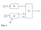
- FIG. 3 shows a block diagram of the system.
- the sensor device 11 transmits the steering wheel angle ⁇ representing signals to a control device 15, in which the electronic stability program (ESP) is implemented.
- the sensor device 12 transmits signals representing the wheel position angle ⁇ in a control device 16 for the electromechanical steering assistance. If appropriate, the corresponding information is then transmitted to the evaluation device 13 in a modified manner in which the actuating signal s is generated in a manner which will be explained in more detail below.
- the signals generated by one or both sensor devices 11 and 12 can also be transmitted directly to the evaluation device 13.
- FIG. 2a shows the case of a driver-side over-regulation, which can occur in very short, pulse-like shocks. Again, a phase shift caused by the impact is observed again, wherein initially the wheel position angle ⁇ leads the steering wheel angle ⁇ .
- the temporal advance of the wheel position angle ⁇ can be determined statistically by a correlation measurement between the two angle courses with respect to the lead time or lag time. For this purpose, the maximum of the correlation is determined. If this is in the range of the lead time for the wheel position angle ⁇ , the damping in the steering is temporarily increased. Otherwise, an increase will not be made.
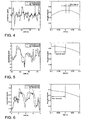
- FIGS. 4 to 6 Now show different states, in each case in the left diagram of the course of the steering wheel link ⁇ and the wheel position angle ⁇ is plotted normalized over time.
- the right diagram represents the associated cross-correlation over time.
- the driver is passive, ie he gives no steering impulse.
- the road bumps move the steering wheel.
- a tracking of the steering wheel angle ⁇ is observed.
- the normalized angular deflections remain smaller than at the wheel side.
- the correlation diagram shows Accordingly, a maximum in the range of the lead time of the Radouswinkels ⁇ . In this case, consequently, the evaluation device 13 will generate a control signal 11 for increasing the damping.
- FIG. 5 shows an active steering intervention by the driver, here are superimposed road bumps.
- the wheel position angle ⁇ follows the steering wheel angle ⁇ , so that the correlation maximum lies in the region of the lag time. In this case, the attenuation is not increased by the evaluation device 13.
- FIG. 6 shows one FIG. 5 corresponding situation in which the driver also actively steers, but the road bumps are significantly lower. In the correlation diagram, this leads to a maximum delay shifted to greater delay, so that here too the evaluation device 13 does not increase the attenuation.
- Another advantage of the invention is that the tuning of the steering with respect to the damping does not have to be carried out over a test track with different ripples and bumps. Rather, the steering adapts to both the road and the steering behavior of the driver.
Landscapes
- Engineering & Computer Science (AREA)
- Transportation (AREA)
- Mechanical Engineering (AREA)
- Chemical & Material Sciences (AREA)
- Combustion & Propulsion (AREA)
- Steering Control In Accordance With Driving Conditions (AREA)
Abstract
Description
Die Erfindung bezieht sich auf ein System zur Verminderung der Lenkradstößigkeit bei einer Kraftfahrzeug-Lenkung.The invention relates to a system for reducing the Lenkradstößigkeit in a motor vehicle steering.
Bei herkömmlichen Kraftfahrzeugen sind die gelenkten Vorderräder mechanisch mit dem Lenkrad gekoppelt. Dies hat zufolge, daß auf die Vorderräder einwirkende Stöße über die Lenkung auf das Lenkrad Kraftfahrzeugs übertragen werden.In conventional motor vehicles, the steered front wheels are mechanically coupled to the steering wheel. This has been said that acting on the front wheels shocks are transmitted via the steering on the steering wheel motor vehicle.
Aus dem Stand der Technik ist es allgemein bekannt, an der Lenkung Lenkungsdämpfer vorzusehen, welche die Stöße mindern sollen. Herkömmliche Systeme arbeiten zumeist passiv, d. h. sie sind nach ihrem Einbau von außen nicht mehr beeinflußbar. So wird beispielsweise in der
Weiterhin ist aus der
Für die Funktion der Stoßdämpfung ist folglich eine sehr schnelle Signalübertragung erforderlich. Zudem werden separate Stoßsensoren für die Erfassung eines Stoßes benötigt. Dementsprechend ist die aus der
Ferner ist aus der
Vor diesem Hintergrund liegt der Erfindung die Aufgabe zugrunde, eine technische einfachere Alternative zur aktiven Verminderung der Lenkradstößigkeit anzuheben.Against this background, the invention has the object to raise a technically simpler alternative to the active reduction of Lenkradstößigkeit.
Diese Aufgabe wird gelöst durch ein System zur Verminderung der Lenkradstößigkeit bei einer Kraftfahrzeug-Lenkung gemäß Patentanspruch 1 gelöst. Das System umfasst eine Sensoreinrichtung zur Erfassung eines Lenkradwinkels, eine Sensoreinrichtung zur Erfassung eines Radstellungswinkels, und eine Auswerteeinrichtung zur Auswertung des zeitlichen Verlaufs der erfassten) Winkel, die derart konfiguriert ist, um zwischen dem Verlauf des Lenkradwinkels und dem Verlauf des Radstellungswinkels eine Phasenverschiebung zu ermitteln und bei einem Voreilen des Radstellungswinkels ein Stellsignal zur Dämpfungserhöhung in der Kraftfahrzeug-Lenkung zu erzeugen.This object is achieved by a system for reducing the Lenkradstößigkeit in a motor vehicle steering solved according to
Hierbei wird die Erkenntnis genutzt, dass in einem Fahrzustand, in dem der Fahrer gerade keinen aktiven Lenkeingriff vornimmt, auf die Lenkung wirkende Stöße zunächst im radnahen Bereich z. B. am Lenkgestänge oder am Lenkgetriebe wirksam werden, bevor sie sich am Lenkrad bemerkbar machen. Der sensorisch erfasste Phasenunterschied zwischen dem Lenkradwinkel und dem Radstellungswinkel zeigt an, ob die an der Lenkung angreifenden Kräfte zuerst von den Rädern oder zuerst vom Lenkrad ausgehen. Eilen die Signale des Radstellungswinkels vor, so wird auf das Vorliegen eines Stoßes geschlossen und dementsprechend über die Generierung eines Stellsignals die Dämpfung in der Lenkung kurzzeitig erhöht. Im umgekehrten Fall kann das normale Dämpfungsniveau beibehalten werden.In this case, the knowledge is used that in a driving state in which the driver is not currently making an active steering intervention, acting on the steering shocks first in the region near the wheel z. B. become effective on the steering linkage or on the steering gear before they make themselves felt on the steering wheel. The sensor-detected phase difference between the steering wheel angle and the wheel position angle indicates whether the forces acting on the steering first emanate from the wheels or first from the steering wheel. If the signals of the wheel position angle accelerate, it is concluded that there is a shock and, accordingly, the generation of a control signal briefly increases the damping in the steering. In the opposite case, the normal damping level can be maintained.
Bei Fahrzeugen, die mit einem elektronischen Stabilitätprogramm (ESP) ausgerüstet sind, wird üblicherweise der Lenkradwinkel als Eingangsgröße benötigt. Ist an dem Fahrzeug zudem eine Lenkung mit elektromechanischer Lenkunterstützung vorgesehen, so wird dort eine den Radstellungswinkel repräsentierender Größe benötigt.For vehicles equipped with an electronic stability program (ESP), the steering wheel angle is usually required as an input. If a steering with electromechanical steering assistance is also provided on the vehicle, a variable representing the wheel position angle is required there.
Die vorliegende Erfindung nutzt diese am Fahrzeug zur Verfügung stehenden Informationen in vorteilhafter Weise zur Ermittlung eines etwaigen Phasenunterschieds zwischen dem Lenkradwinkel und dem Radstellungswinkel zur Verminderung der Lenkradstößigkeit aus. In diesem Fall sind am Fahrzeug keine zusätzlichen Sensoren anzubringen. Vielmehr wird die ohnehin vorhandene Sensorik mit einem Zusatznutzen versehen.The present invention advantageously uses this information available on the vehicle to determine a possible phase difference between the steering wheel angle and the Radstellungswinkel to reduce the Lenkradstößigkeit. In this case, no additional sensors should be fitted to the vehicle. Rather, the already existing sensors are provided with an additional benefit.
Dadurch läßt sich mit einem sehr geringen Aufwand einen Komfortgewinn bei unebener Fahrbahn erzielen.As a result, can be achieved with a very little effort a gain in comfort on uneven roads.
Die Signale der Sensoreinrichtungen für die Auswerteeinrichtung, die mit hoher Präzision vorliegen müssen, können sowohl analog als auch digital zur Verfügung gestellt werden.The signals of the sensor devices for the evaluation device, which must be available with high precision, can be made available both analogously and digitally.
Das zeitliche Voreilen des Radstellungswinkels wird statistisch durch eine Korrelationsmessung zwischen den beiden Winkelverläufen in bezug auf die Voreil- bzw. Nacheilzeit des Radstellungswinkels anhand des Maximums der Korrelation detektiert. Liegt das Maximum des Korrelationskoeffizienten im Bereich einer Voreilzeit, so wird die Dämpfung erhöht, und zwar vorzugsweise solange, wie dieser Zustand anhält.The temporal advance of the wheel position angle is detected statistically by a correlation measurement between the two angle courses with respect to the lead time of the wheel position angle from the maximum of the correlation. If the maximum of the correlation coefficient is in the range of a lead time, the attenuation is increased, preferably as long as this state persists.
In einer weiteren, vorteilhaften Ausgestaltung weist die Lenkung zur Lenkunterstützung einen Servomotor mit einem Rotor auf. Die Sensoreinrichtung zur Erfassung des Radstellungswinkels greift dann vorzugsweise die Winkelstellung des Rotors ab. Dabei kann außerdem zusätzlich die Drehzahl des Rotors erfaßt und in der Auswerteeinrichtung für die Stellsignalgenerierung mitausgewertet wird.In a further advantageous embodiment, the steering for steering assistance to a servo motor with a rotor. The sensor device for detecting the wheel position angle then preferably picks up the angular position of the rotor. In addition, the rotational speed of the rotor can also be detected and also evaluated in the evaluation device for the actuating signal generation.
Allerdings kann der Radstellungswinkel auch an anderer Stelle und unabhängig von einer elektrischen Servoeinrichtung radnah erfaßt werden. Prinzipiell kann hierzu auch ein eigener Sensor vorgesehen werden. Dies gilt analog auch für den Fall der Lenkradwinkelerfassung, die nicht notwendigerweise im Zusammenhang mit einem elektronischen Stabilitätsprogramm erfolgen muß.However, the Radstellungswinkel can be detected radnah elsewhere and independently of an electric servo. In principle, a separate sensor can also be provided for this purpose. This also applies analogously to the case of the steering wheel angle detection, which need not necessarily take place in connection with an electronic stability program.
Die Erhöhung der Dämpfung erfolgt beispielsweise über einen zuschaltbaren Lenkungsdämpfer, der durch das Stellsignal aktivierbar und deaktivierbar ist.The increase of the damping takes place for example via a switchable steering damper, which can be activated and deactivated by the control signal.
Denkbar ist darüber hinaus, in Abhängigkeit der ermittelten Voreilzeit und/oder in Abhängigkeit der in einem solchen Fall erfaßten Radstellungswinkelamplituden ein entsprechend vorgegebenes Dämpfungsniveau einzustellen. Hierdurch läßt sich eine optimale Dämpfungswirkung erzielen.It is also conceivable, depending on the determined lead time and / or depending on the detected in such a case Radstellungswinkelamplituden a set according to the specified damping level. As a result, an optimal damping effect can be achieved.
Nachfolgend wird die Erfindung anhand eines in der Zeichnung dargestellten Ausführungsbeispiels näher erläutert. Die Zeichnung zeigt in:
Figur 1- eine Lenkung für ein Kraftfahrzeug mit einem System zur Verminderung der Lenkradstößigkeit nach der Erfindung in schematischer Darstellung,
Figur 2- ein Diagramm zur Veranschaulichung des Kennlinienverlaufs eines Lenkradwinkels und eines Radstellungswinkel,
- Figur 2a
- ein weiteres Diagramm zur Veranschaulichung des Kennlinienverlaufs eines Lenkradwinkels und eines Radstellungswinkels bei impulsartigen Stoßbedingungen,
Figur 3- einen Blockschaltbild des erfindungsgemäßen Systems zur Verminderung der Lenkradstößigkeit aus
Figur 1 Figur 4- ein Diagramm zur Veranschaulichung des Kennlinienverlaufs eines Lenkradwinkels und eines Radstellungswinkel bei einem passiven Fahrer und unebener Fahrbahn sowie ein Diagramm für die zugehörige Kreuzkorrelation zwischen dem Lenkradwinkel und dem Radstellungswinkel in bezug auf die Voreilzeit des Radstellungswinkels,
Figur 5- eine Darstellung entsprechend
Figur 4 Figur 6- eine Darstellung entsprechend
Figur 4
- FIG. 1
- a steering system for a motor vehicle with a steering wheel steering reduction system according to the invention in a schematic representation,
- FIG. 2
- a diagram illustrating the characteristic curve of a steering wheel angle and a Radstellungswinkel,
- FIG. 2a
- Another diagram illustrating the characteristic curve of a steering wheel angle and a Radstellungswinkels in pulse-like shock conditions,
- FIG. 3
- a block diagram of the system according to the invention for reducing Lenkradstößigkeit
FIG. 1 . - FIG. 4
- a diagram illustrating the characteristic curve of a steering wheel angle and a Radstellungswinkel in a passive driver and uneven road and a graph for the associated cross-correlation between the steering wheel angle and the Radstellungswinkel with respect to the lead time of the Radstellungswinkels
- FIG. 5
- a representation accordingly
FIG. 4 in an active steering intervention of the driver on uneven roads, and in - FIG. 6
- a representation accordingly
FIG. 4 in an active steering intervention of the driver on a substantially flat roadway.
Das in den Figuren dargestellte Ausführungsbeispiel zeigt eine Lenkung 1 eines Kraftfahrzeugs. Die Lenkung umfaßt ein Lenkrad 2, das über eine Lenkspindel 3 mit einem Lenkgetriebe 4 mechanisch gekoppelt ist. Ein am Lenkrad 2 eingebrachter Lenkbefehl wird über die Lenkspindel 3 und das Lenkgetriebe 4 auf eine Zahnstange 5 übertragen, die ihrerseits mit Spurstangen 6 gekoppelt ist. Die Spurstangen 6 greifen jeweils an einem Radträger 7 an, der ein Fahrzeugrad 8 lagert.The embodiment shown in the figures shows a
Die Lenkung 1 weist weiterhin einen elektrischen Servomotor 9 zur Lenkunterstützung auf. Zur Erfassung des Moments in der Lenkung, in Abhängigkeit dessen der Servomotor 9 angesteuert wird, dient einen Torsionssensor 10 in der Art eines Torsionsstabs, der in die Lenkspindel 3 eingegliedert ist.The
Weiterhin ist an der Lenkung ein System zur Verminderung der Lenkradstößigkeit vorgesehen. Dieses umfaßt eine Sensoreinrichtung 11 zur Erfassung eines Lenkradwinkels α sowie eine Sensoreinrichtung 12 zur Erfassung eines Radstellungswinkels β. Diese Sensoreinrichtungen 11 und 12 können in herkömmlicher Art und Weise ausgebildet sein.Furthermore, a system for reducing the Lenkradstößigkeit is provided on the steering. This comprises a
Bei dem hier dargestellten Ausführungsbeispiel ist die Sensoreinrichtung 11 in ein elektronisches Stabilitätsprogramm (ESP) integriert. Für das System zur Verminderung der Lenkradstößigkeit wird dann lediglich die entsprechende Information aus dem elektrischen Stabilitätsprogramm abgegriffen.In the exemplary embodiment illustrated here, the
In entsprechender Weise wird hier der Radstellungswinkel β aus einer Steuerung der elektromechanischen Lenkunterstützung, d. h. der Ansteuerung des Servomotors 9 abgegriffen. Die entsprechende Sensoreinrichtung 12 ist dabei an dem Servomotor 9 vorgesehen und erfaßt die Stellung eines Rotors desselben. Zusätzlich kann auch die Drehzahl des Rotors erfaßt und dem System zur Verminderung der Lenkradstößigkeit zur Verfügung gestellt werden. Die Rotorstellung repräsentiert dabei den Radstellungswinkel β.Similarly, here the wheel position angle β from a control of the electromechanical steering assistance, d. H. the control of the servomotor 9 tapped. The corresponding
In einer Abwandlung des Ausführungsbeispiels kann zur Erfassung des Radstellungswinkels β eine im Bereich der Radträger 7 oder der Spurstangen 6 angeordnete Sensoreinrichtung 12 zum Einsatz kommen. Durch die radnähere Anordnung werden durch Fahrbahnunebenheiten verursachte Stöße noch etwas früher wahrgenommen und der Einfluß des Übertragungsverhaltens zwischen den Rädern 8 und dem Servomotor 9 verringert.In a modification of the exemplary embodiment, a
Das System zur Verminderung der Lenkradstößigkeit umfaßt weiterhin eine Auswerteeinrichtung 13, die den zeitlichen Verlauf der erfaßten Signale bzw. der erfaßten Winkel auswertet. Die Auswerteeinrichtung 13 ist derart konfiguriert, um zwischen dem Verlauf des Lenkradwinkels α und dem Verlauf des Radstellungswinkels β eine Phasenverschiebung zu ermitteln und bei einem Voreilen des Radstellungswinkels β ein Stellsignal s zur Dämpfungserhöhung in der Kraftfahrzeug-Lenkung zu erzeugen.The system for reducing the Steering wheel bumps further comprises an
Alternativ oder ergänzend können für die Generierung des Stellsignals s die Änderungsgeschwindigkeiten für den Lenkradwinkel α und den Radstellungswinkel β ausgewertet werden.Alternatively or additionally, the change speeds for the steering wheel angle α and the wheel position angle β can be evaluated for the generation of the actuating signal s.
Das Stellsignal s wird dann einem nicht näher dargestellten Lenkungsdämpfer 14 der Lenkung zugeführt, der durch dieses aktiviert bzw. deaktiviert wird. Auf diese Weise läßt sich für einen Stoß die Dämpfung in der Lenkung temporär erhöhen. In einer weiteren Abwandlung des Ausführungsbeispiels kann die Dämpfung durch das Stellsignal auch quantitativ beeinflußt werden. Das Ausmaß der Dämpfung läßt sich dann in Abhängigkeit der Voreilzeit des Radstellungswinkels β und/oder der Amplituden des Radstellungswinkel β einstellen.The control signal s is then supplied to a
Der zeitliche Zusammenhang zwischen dem Lenkradwinkel α und dem Radstellungswinkel β im Falle eines radseitigen Stoßes ist in den
Nach einer Reaktionszeit des Fahrers kommt es zum Zeitpunkt t3 zu einer Gegenreaktion, nämlich einem Gegenlenken, um die ursprüngliche Fahrtrichtung wieder herzustellen. Zumindest bis zu diesem Zeitpunkt t3 eilt der Radstellungswinkel β dem Lenkradwinkel α voraus, so daß im Kurvenverlauf eine Phasenverschiebung zu beobachten ist.After a reaction time of the driver, it comes at time t 3 to a backlash, namely a counter-steering to restore the original direction of travel. At least until this time t 3, the wheel position angle β precedes the steering wheel angle α, so that a phase shift can be observed in the course of the curve.
Die vom Fahrer veranlaßte Korrektur endet zum Zeitpunkt t4. Hier tritt nun aus den oben bereits geschilderten Gründen wiederum eine Zeitverzögerung auf, so daß sich der ursprüngliche Radstellungswinkel β erst zu einem späteren Zeitpunkt t5 wieder eingestellt.The correction caused by the driver ends at time t 4 . Here, for the reasons already described above, a time delay again occurs, so that the original wheel position angle β is set again only at a later time t 5 .
Das zeitliche Voreilen des Radstellungswinkels β kann statistisch durch eine Korrelationsmessung zwischen den beiden Winkelverläufen in bezug auf die Voreil- bzw. Nacheilzeit ermittelt werden. Dazu wird das Maximum der Korrelation bestimmt. Liegt dieses im Bereich der Voreilzeit für den Radstellungswinkel β, so wird die Dämpfung in der Lenkung zeitweilig erhöht. Andernfalls wird eine Erhöhung nicht vorgenommen.The temporal advance of the wheel position angle β can be determined statistically by a correlation measurement between the two angle courses with respect to the lead time or lag time. For this purpose, the maximum of the correlation is determined. If this is in the range of the lead time for the wheel position angle β, the damping in the steering is temporarily increased. Otherwise, an increase will not be made.
Die
Bei dem in
Bei einem aktiv lenkenden Fahrer behindert somit keine zusätzliche Dämpfung das Lenkverhalten.In an actively steering driver thus hinders no additional damping the steering behavior.
Ein weiterer Vorteil der Erfindung besteht darin, daß die Abstimmung der Lenkung bezüglich der Dämpfung nicht über eine Teststrecke mit verschiedenen Welligkeiten und Stößigkeiten durchgeführt werden muß. Vielmehr paßt sich die Lenkung sowohl der Fahrbahn als auch dem Lenkverhalten des Fahrers an.Another advantage of the invention is that the tuning of the steering with respect to the damping does not have to be carried out over a test track with different ripples and bumps. Rather, the steering adapts to both the road and the steering behavior of the driver.
Die Erfindung wurde vorstehend anhand eines Ausführungsbeispiels lediglich beispielhaft erläutert. Sie ist jedoch nicht auf dieses Ausführungsbeispiel beschränkt, sondern umfaßt vielmehr alle durch die Patentansprüche definierten Ausgestaltungsformen.The invention has been explained above by way of example only by way of example. However, it is not limited to this embodiment, but rather includes all the embodiments defined by the claims.
- 11
- Lenkungsteering
- 22
- Lenkradsteering wheel
- 33
- Lenkspindelsteering shaft
- 44
- Lenkgetriebesteering gear
- 55
- Zahnstangerack
- 66
- Spurstangetie rod
- 77
- Radträgerwheel carrier
- 88th
- Radwheel
- 99
- Servomotorservomotor
- 1010
- Torsionssensortorsion sensor
- 1111
- Sensoreinrichtung für den Lenkradwinkel αSensor device for the steering wheel angle α
- 1212
- Sensoreinrichtung für den Radstellungswinkel βSensor device for the wheel position angle β
- 1313
- Auswerteeinrichtungevaluation
- 1414
- Lenkungsdämpfersteering damper
- 1515
- Steuereinrichtung für ein elektronisches Stabilitätsprogramm (ESP)Control Device for an Electronic Stability Program (ESP)
- 1616
- Steuereinrichtung für eine elektromechanischen LenkunterstützungControl device for an electromechanical steering assistance
- αα
- Lenkradwinkelsteering wheel angle
- ββ
- Radstellungswinkelwheel position
- ss
- Stellsignalactuating signal
- tt
- ZeitTime
Claims (6)
- System for reducing the steering wheel shocks in a motor vehicle steering system, comprising:- a sensor device (11) for sensing a steering angle (α),- a sensor device (12) for sensing a wheel position angle (β), and- an evaluation device (13) for evaluating the time profile of the sensed angles (α, β) which is configured in such a way that it determines a phase shift between the profile of the steering wheel angle (α) and the profile of the wheel position angle (β),characterized in that
in the case of leading of the wheel position angle (β) the damping in the motor vehicle steering system (1) is increased by means of an actuation signal (s), and the temporal leading of the wheel position angle (β) is detected statistically by means of a correlation measured between the two angular profiles with respect to the lead time or lag time by means of the maximum value of the correlation. - System according to Claim 1, characterized in that the steering wheel angle (α) is tapped from an electrical stability programme (ESP).
- System according to one of Claims 1 or 2, characterized in that the wheel position angle (β) is tapped from a controller for an electro-mechanical steering assistance system.
- System according to one of Claims 1 to 3, characterized in that the steering system for providing steering assistance has a servo motor (9) with a rotor, and the sensor device (12) senses the angular position of the rotor in order to sense the wheel position angle (β).
- System according to Claim 4, characterized in that the rotational speed of the rotor is additionally sensed and is also evaluated in the evaluation device (13) for the generation of the actuation signals.
- System according to one of Claims 1 to 5, characterized in that the steering system (1) has a steering damper (14) which can be activated by means of the actuation signal (s).
Applications Claiming Priority (2)
| Application Number | Priority Date | Filing Date | Title |
|---|---|---|---|
| DE10317991 | 2003-04-19 | ||
| DE10317991A DE10317991A1 (en) | 2003-04-19 | 2003-04-19 | System for reducing steering wheel jerkiness in motor vehicle steering |
Publications (3)
| Publication Number | Publication Date |
|---|---|
| EP1468898A2 EP1468898A2 (en) | 2004-10-20 |
| EP1468898A3 EP1468898A3 (en) | 2006-06-07 |
| EP1468898B1 true EP1468898B1 (en) | 2011-10-05 |
Family
ID=32892430
Family Applications (1)
| Application Number | Title | Priority Date | Filing Date |
|---|---|---|---|
| EP04005218A Expired - Lifetime EP1468898B1 (en) | 2003-04-19 | 2004-03-05 | System to reduce steering wheel shocks for an automotive steering system |
Country Status (3)
| Country | Link |
|---|---|
| EP (1) | EP1468898B1 (en) |
| AT (1) | ATE527158T1 (en) |
| DE (1) | DE10317991A1 (en) |
Families Citing this family (14)
| Publication number | Priority date | Publication date | Assignee | Title |
|---|---|---|---|---|
| DE102005003180B4 (en) | 2005-01-19 | 2015-04-02 | Volkswagen Ag | Device and method for reducing false excitations on the steering wheel |
| DE102007026189A1 (en) | 2007-06-05 | 2008-12-11 | Volkswagen Ag | Electromechanical steering mechanism for motor vehicle i.e. passenger car, has high pass filter for filtering difference signal, where high pass filtered difference signal is modulated with signal that represents additional steering moment |
| DE102008026730A1 (en) | 2008-06-04 | 2009-12-17 | Volkswagen Ag | Electromechanical steering has electro motor for steering aid, where steering control device is provided for detecting steering aid depending on detected hand moment of driver |
| DE102008059906B4 (en) | 2008-12-02 | 2015-04-02 | Volkswagen Ag | Electric Power Steering |
| DE102008061696A1 (en) * | 2008-12-10 | 2010-06-17 | Volkswagen Ag | Electromechanical steering and method for determining a road condition |
| DE102009047586A1 (en) * | 2009-12-07 | 2011-06-09 | Zf Lenksysteme Gmbh | Method and device for compensation of interference information in an electric steering system |
| DE102011052881B4 (en) * | 2011-08-22 | 2018-05-17 | Robert Bosch Automotive Steering Gmbh | Method for determining a rack-and-pinion force for a steering device in a vehicle, steering device and control and / or regulating device for a steering device |
| JP2013184622A (en) | 2012-03-09 | 2013-09-19 | Hitachi Automotive Systems Steering Ltd | Electric power steering system, and controller of electric power steering system |
| DE102014218686A1 (en) * | 2014-09-17 | 2016-03-17 | Continental Automotive Gmbh | Method for compensation of obstacle influences in a steering device, steering control device, steering device and storage medium |
| GB2541664A (en) * | 2015-08-24 | 2017-03-01 | Jaguar Land Rover Ltd | Dampening lateral vehicle disturbances |
| US9738309B2 (en) * | 2015-11-30 | 2017-08-22 | Steering Solutions Ip Holding Corporation | Active-damping based approach to mitigate effects of rack disturbances on EPS systems |
| CN113184050B (en) * | 2021-05-31 | 2022-12-09 | 重庆长安汽车股份有限公司 | Compensation method and compensation system for shimmy of vehicle steering wheel |
| DE102023202152A1 (en) * | 2023-03-10 | 2024-09-12 | Robert Bosch Gesellschaft mit beschränkter Haftung | Device and method for damping a steering movement in an active steering system of a vehicle, vehicle comprising the device |
| DE102023128596A1 (en) * | 2023-10-18 | 2025-04-24 | Cariad Se | Method for operating a steering system for detecting disturbances induced by road irregularities |
Family Cites Families (14)
| Publication number | Priority date | Publication date | Assignee | Title |
|---|---|---|---|---|
| JPH0662092B2 (en) * | 1986-04-11 | 1994-08-17 | 本田技研工業株式会社 | Electric power steering device |
| DE3724070A1 (en) * | 1987-07-21 | 1989-02-02 | Teves Gmbh Alfred | METHOD AND DEVICE FOR MANUFACTURING A VEHICLE |
| EP0350819B1 (en) * | 1988-07-11 | 1993-12-29 | Koyo Seiko Co., Ltd. | Steering angle middle point detecting apparatus |
| US5141069A (en) * | 1988-09-13 | 1992-08-25 | Aisin Seiki Kabushiki Kaisha | Steering mechanism with toe-in control |
| DE3929177A1 (en) * | 1989-09-02 | 1991-03-07 | Bosch Gmbh Robert | METHOD FOR INFLUENCING THE DAMPING OF A POWER STEERING STEERING |
| GB2245873B (en) * | 1990-04-18 | 1994-03-16 | Nissan Motor | Control system for optimizing operation of vehicle performance/safety enhancing systems |
| US5333700A (en) * | 1991-08-26 | 1994-08-02 | Fuji Jukogyo Kabushiki Kaisha | Steering system for a motor vehicle |
| US5596252A (en) * | 1993-12-06 | 1997-01-21 | Honda Giken Kogyo Kabushiki Kaisha | Electrically operated power steering apparatus for assisting manual steering operation in a motor vehicle |
| JPH0811728A (en) * | 1994-06-29 | 1996-01-16 | Nippon Seiko Kk | Electric power steering device |
| DE4446123C2 (en) * | 1994-12-22 | 2003-05-22 | Man Nutzfahrzeuge Ag | Device for acting on the interference forces acting on the steering of a motor vehicle |
| DE19644528C1 (en) * | 1996-10-26 | 1998-04-02 | Mercedes Benz Lenkungen Gmbh | Steering system for motor vehicles |
| JP3344464B2 (en) * | 1998-05-18 | 2002-11-11 | トヨタ自動車株式会社 | Vehicle steering control device |
| EP1279584B1 (en) * | 2001-07-28 | 2006-05-10 | Ford Global Technologies, LLC | Electrical steering assistant suppressing brake-induced vibrations |
| FR2845341B1 (en) * | 2002-10-04 | 2004-11-12 | Soc Mecanique Irigny | METHOD FOR ACTIVE STABILIZATION OF A MOTOR VEHICLE STEERING SYSTEM |
-
2003
- 2003-04-19 DE DE10317991A patent/DE10317991A1/en not_active Ceased
-
2004
- 2004-03-05 EP EP04005218A patent/EP1468898B1/en not_active Expired - Lifetime
- 2004-03-05 AT AT04005218T patent/ATE527158T1/en active
Also Published As
| Publication number | Publication date |
|---|---|
| EP1468898A3 (en) | 2006-06-07 |
| EP1468898A2 (en) | 2004-10-20 |
| ATE527158T1 (en) | 2011-10-15 |
| DE10317991A1 (en) | 2004-10-28 |
Similar Documents
| Publication | Publication Date | Title |
|---|---|---|
| EP1468898B1 (en) | System to reduce steering wheel shocks for an automotive steering system | |
| DE102005003180B4 (en) | Device and method for reducing false excitations on the steering wheel | |
| EP3256364B1 (en) | Method for learning an admissible steering angle by a vehicle steering device | |
| EP3727998B1 (en) | Method for operating a steer-by-wire steering system for a motor vehicle, and steering system for a motor vehicle | |
| DE102009020157A1 (en) | Servomotor virtual rotor angle computing method for vehicles, involves illustrating dynamic transfer behavior of mechanical transmission route by model-assisted transfer function between pinion angle and rotor angle | |
| DE102008026730A1 (en) | Electromechanical steering has electro motor for steering aid, where steering control device is provided for detecting steering aid depending on detected hand moment of driver | |
| EP4108544B1 (en) | Steer-by-wire steering column for a motor vehicle | |
| EP1767437B1 (en) | Steering-pull compensation device for motor vehicle | |
| DE102011120917B4 (en) | Vehicle steering system and method for operating a vehicle steering system | |
| DE102013008830B3 (en) | Method for detecting damage to track rod of steering train of motor car, involves storing defect entry in fault memory when deviation of straight-line steering angle from another steering angle is greater than predetermined threshold value | |
| DE102008059906B4 (en) | Electric Power Steering | |
| DE102010032043B4 (en) | Steering system and method of operating the steering system | |
| EP2117907B1 (en) | Method for adjusting driven wheels of a motor vehicle | |
| DE102008055873A1 (en) | Electromechanical servo-steering system for motor vehicle, has error control for monitoring correct function of torque sensor, and adjusting signal producing emergency operation support torque that is independent of output signal of sensor | |
| DE102014208926A1 (en) | A determination device for determining a support torque and support device and method for supporting a steering torque applied by a driver to a steering system of the vehicle | |
| EP3621832A1 (en) | Roll stabilizer having sensors for state determination | |
| EP1680301B1 (en) | Vehicle control system | |
| DE102017213415B4 (en) | Method of operating a steering device | |
| EP3298871B1 (en) | Agricultural vehicle, process for detecting a mechanical load on components of an agricultural vehicle | |
| DE19644528C1 (en) | Steering system for motor vehicles | |
| EP3971064B1 (en) | Determining a steering reference state by means of wheel speed variables | |
| DE102005047144A1 (en) | System for removing natural oscillations of front wheel guidance in single-lane motor vehicle, has actuator formed for automatic contact in vehicle control so that guidance moment is generated for reduction of natural oscillation | |
| DE102008021847B4 (en) | Electromechanical steering system and method for controlling an electromechanical steering system | |
| DE102010014802B4 (en) | Steering system of a motor vehicle | |
| DE102009011853A1 (en) | Electric power steering systems for vehicles with adjustable torsion bar springs and methods of retrofitting electric power steering systems for vehicles |
Legal Events
| Date | Code | Title | Description |
|---|---|---|---|
| PUAI | Public reference made under article 153(3) epc to a published international application that has entered the european phase |
Free format text: ORIGINAL CODE: 0009012 |
|
| AK | Designated contracting states |
Kind code of ref document: A2 Designated state(s): AT BE BG CH CY CZ DE DK EE ES FI FR GB GR HU IE IT LI LU MC NL PL PT RO SE SI SK TR |
|
| AX | Request for extension of the european patent |
Extension state: AL LT LV MK |
|
| PUAL | Search report despatched |
Free format text: ORIGINAL CODE: 0009013 |
|
| AK | Designated contracting states |
Kind code of ref document: A3 Designated state(s): AT BE BG CH CY CZ DE DK EE ES FI FR GB GR HU IE IT LI LU MC NL PL PT RO SE SI SK TR |
|
| AX | Request for extension of the european patent |
Extension state: AL LT LV MK |
|
| 17P | Request for examination filed |
Effective date: 20061207 |
|
| AKX | Designation fees paid |
Designated state(s): AT BE BG CH CY CZ DE DK EE ES FI FR GB GR HU IE IT LI LU MC NL PL PT RO SE SI SK TR |
|
| 17Q | First examination report despatched |
Effective date: 20071017 |
|
| REG | Reference to a national code |
Ref country code: DE Ref legal event code: R079 Ref document number: 502004012912 Country of ref document: DE Free format text: PREVIOUS MAIN CLASS: B62D0006060000 Ipc: B62D0005040000 |
|
| RIC1 | Information provided on ipc code assigned before grant |
Ipc: B62D 5/04 20060101AFI20110228BHEP |
|
| RTI1 | Title (correction) |
Free format text: SYSTEM TO REDUCE STEERING WHEEL SHOCKS FOR AN AUTOMOTIVE STEERING SYSTEM |
|
| GRAP | Despatch of communication of intention to grant a patent |
Free format text: ORIGINAL CODE: EPIDOSNIGR1 |
|
| GRAS | Grant fee paid |
Free format text: ORIGINAL CODE: EPIDOSNIGR3 |
|
| GRAA | (expected) grant |
Free format text: ORIGINAL CODE: 0009210 |
|
| AK | Designated contracting states |
Kind code of ref document: B1 Designated state(s): AT BE BG CH CY CZ DE DK EE ES FI FR GB GR HU IE IT LI LU MC NL PL PT RO SE SI SK TR |
|
| REG | Reference to a national code |
Ref country code: GB Ref legal event code: FG4D Free format text: NOT ENGLISH |
|
| REG | Reference to a national code |
Ref country code: CH Ref legal event code: EP |
|
| REG | Reference to a national code |
Ref country code: IE Ref legal event code: FG4D |
|
| REG | Reference to a national code |
Ref country code: DE Ref legal event code: R096 Ref document number: 502004012912 Country of ref document: DE Effective date: 20111208 |
|
| REG | Reference to a national code |
Ref country code: NL Ref legal event code: VDEP Effective date: 20111005 |
|
| PG25 | Lapsed in a contracting state [announced via postgrant information from national office to epo] |
Ref country code: SI Free format text: LAPSE BECAUSE OF FAILURE TO SUBMIT A TRANSLATION OF THE DESCRIPTION OR TO PAY THE FEE WITHIN THE PRESCRIBED TIME-LIMIT Effective date: 20111005 |
|
| REG | Reference to a national code |
Ref country code: IE Ref legal event code: FD4D |
|
| PG25 | Lapsed in a contracting state [announced via postgrant information from national office to epo] |
Ref country code: GR Free format text: LAPSE BECAUSE OF FAILURE TO SUBMIT A TRANSLATION OF THE DESCRIPTION OR TO PAY THE FEE WITHIN THE PRESCRIBED TIME-LIMIT Effective date: 20120106 Ref country code: PT Free format text: LAPSE BECAUSE OF FAILURE TO SUBMIT A TRANSLATION OF THE DESCRIPTION OR TO PAY THE FEE WITHIN THE PRESCRIBED TIME-LIMIT Effective date: 20120206 Ref country code: SE Free format text: LAPSE BECAUSE OF FAILURE TO SUBMIT A TRANSLATION OF THE DESCRIPTION OR TO PAY THE FEE WITHIN THE PRESCRIBED TIME-LIMIT Effective date: 20111005 Ref country code: NL Free format text: LAPSE BECAUSE OF FAILURE TO SUBMIT A TRANSLATION OF THE DESCRIPTION OR TO PAY THE FEE WITHIN THE PRESCRIBED TIME-LIMIT Effective date: 20111005 |
|
| PG25 | Lapsed in a contracting state [announced via postgrant information from national office to epo] |
Ref country code: CY Free format text: LAPSE BECAUSE OF FAILURE TO SUBMIT A TRANSLATION OF THE DESCRIPTION OR TO PAY THE FEE WITHIN THE PRESCRIBED TIME-LIMIT Effective date: 20111005 |
|
| RAP2 | Party data changed (patent owner data changed or rights of a patent transferred) |
Owner name: VOLKSWAGEN AKTIENGESELLSCHAFT |
|
| PG25 | Lapsed in a contracting state [announced via postgrant information from national office to epo] |
Ref country code: EE Free format text: LAPSE BECAUSE OF FAILURE TO SUBMIT A TRANSLATION OF THE DESCRIPTION OR TO PAY THE FEE WITHIN THE PRESCRIBED TIME-LIMIT Effective date: 20111005 Ref country code: SK Free format text: LAPSE BECAUSE OF FAILURE TO SUBMIT A TRANSLATION OF THE DESCRIPTION OR TO PAY THE FEE WITHIN THE PRESCRIBED TIME-LIMIT Effective date: 20111005 Ref country code: CZ Free format text: LAPSE BECAUSE OF FAILURE TO SUBMIT A TRANSLATION OF THE DESCRIPTION OR TO PAY THE FEE WITHIN THE PRESCRIBED TIME-LIMIT Effective date: 20111005 Ref country code: DK Free format text: LAPSE BECAUSE OF FAILURE TO SUBMIT A TRANSLATION OF THE DESCRIPTION OR TO PAY THE FEE WITHIN THE PRESCRIBED TIME-LIMIT Effective date: 20111005 Ref country code: IE Free format text: LAPSE BECAUSE OF FAILURE TO SUBMIT A TRANSLATION OF THE DESCRIPTION OR TO PAY THE FEE WITHIN THE PRESCRIBED TIME-LIMIT Effective date: 20111005 |
|
| PLBE | No opposition filed within time limit |
Free format text: ORIGINAL CODE: 0009261 |
|
| STAA | Information on the status of an ep patent application or granted ep patent |
Free format text: STATUS: NO OPPOSITION FILED WITHIN TIME LIMIT |
|
| PG25 | Lapsed in a contracting state [announced via postgrant information from national office to epo] |
Ref country code: IT Free format text: LAPSE BECAUSE OF FAILURE TO SUBMIT A TRANSLATION OF THE DESCRIPTION OR TO PAY THE FEE WITHIN THE PRESCRIBED TIME-LIMIT Effective date: 20111005 Ref country code: PL Free format text: LAPSE BECAUSE OF FAILURE TO SUBMIT A TRANSLATION OF THE DESCRIPTION OR TO PAY THE FEE WITHIN THE PRESCRIBED TIME-LIMIT Effective date: 20111005 Ref country code: RO Free format text: LAPSE BECAUSE OF FAILURE TO SUBMIT A TRANSLATION OF THE DESCRIPTION OR TO PAY THE FEE WITHIN THE PRESCRIBED TIME-LIMIT Effective date: 20111005 |
|
| 26N | No opposition filed |
Effective date: 20120706 |
|
| BERE | Be: lapsed |
Owner name: VOLKSWAGEN A.G. Effective date: 20120331 |
|
| PG25 | Lapsed in a contracting state [announced via postgrant information from national office to epo] |
Ref country code: MC Free format text: LAPSE BECAUSE OF NON-PAYMENT OF DUE FEES Effective date: 20120331 |
|
| REG | Reference to a national code |
Ref country code: CH Ref legal event code: PL Ref country code: DE Ref legal event code: R097 Ref document number: 502004012912 Country of ref document: DE Effective date: 20120706 |
|
| GBPC | Gb: european patent ceased through non-payment of renewal fee |
Effective date: 20120305 |
|
| REG | Reference to a national code |
Ref country code: FR Ref legal event code: ST Effective date: 20121130 |
|
| PG25 | Lapsed in a contracting state [announced via postgrant information from national office to epo] |
Ref country code: BE Free format text: LAPSE BECAUSE OF NON-PAYMENT OF DUE FEES Effective date: 20120331 Ref country code: FR Free format text: LAPSE BECAUSE OF NON-PAYMENT OF DUE FEES Effective date: 20120402 Ref country code: LI Free format text: LAPSE BECAUSE OF NON-PAYMENT OF DUE FEES Effective date: 20120331 Ref country code: GB Free format text: LAPSE BECAUSE OF NON-PAYMENT OF DUE FEES Effective date: 20120305 Ref country code: CH Free format text: LAPSE BECAUSE OF NON-PAYMENT OF DUE FEES Effective date: 20120331 |
|
| PG25 | Lapsed in a contracting state [announced via postgrant information from national office to epo] |
Ref country code: ES Free format text: LAPSE BECAUSE OF FAILURE TO SUBMIT A TRANSLATION OF THE DESCRIPTION OR TO PAY THE FEE WITHIN THE PRESCRIBED TIME-LIMIT Effective date: 20120116 |
|
| REG | Reference to a national code |
Ref country code: AT Ref legal event code: MM01 Ref document number: 527158 Country of ref document: AT Kind code of ref document: T Effective date: 20120305 |
|
| PG25 | Lapsed in a contracting state [announced via postgrant information from national office to epo] |
Ref country code: FI Free format text: LAPSE BECAUSE OF FAILURE TO SUBMIT A TRANSLATION OF THE DESCRIPTION OR TO PAY THE FEE WITHIN THE PRESCRIBED TIME-LIMIT Effective date: 20111005 Ref country code: BG Free format text: LAPSE BECAUSE OF FAILURE TO SUBMIT A TRANSLATION OF THE DESCRIPTION OR TO PAY THE FEE WITHIN THE PRESCRIBED TIME-LIMIT Effective date: 20120105 |
|
| PG25 | Lapsed in a contracting state [announced via postgrant information from national office to epo] |
Ref country code: AT Free format text: LAPSE BECAUSE OF NON-PAYMENT OF DUE FEES Effective date: 20120305 |
|
| PG25 | Lapsed in a contracting state [announced via postgrant information from national office to epo] |
Ref country code: TR Free format text: LAPSE BECAUSE OF FAILURE TO SUBMIT A TRANSLATION OF THE DESCRIPTION OR TO PAY THE FEE WITHIN THE PRESCRIBED TIME-LIMIT Effective date: 20111005 |
|
| PG25 | Lapsed in a contracting state [announced via postgrant information from national office to epo] |
Ref country code: LU Free format text: LAPSE BECAUSE OF NON-PAYMENT OF DUE FEES Effective date: 20120305 |
|
| PG25 | Lapsed in a contracting state [announced via postgrant information from national office to epo] |
Ref country code: HU Free format text: LAPSE BECAUSE OF FAILURE TO SUBMIT A TRANSLATION OF THE DESCRIPTION OR TO PAY THE FEE WITHIN THE PRESCRIBED TIME-LIMIT Effective date: 20040305 |
|
| PGFP | Annual fee paid to national office [announced via postgrant information from national office to epo] |
Ref country code: DE Payment date: 20230331 Year of fee payment: 20 |
|
| P01 | Opt-out of the competence of the unified patent court (upc) registered |
Effective date: 20230523 |
|
| REG | Reference to a national code |
Ref country code: DE Ref legal event code: R071 Ref document number: 502004012912 Country of ref document: DE |