EP1467194A1 - Verfahren und Vorrichtung zur Detektion, Charakterisierung und/oder Elimination von Schwebeteilchen - Google Patents
Verfahren und Vorrichtung zur Detektion, Charakterisierung und/oder Elimination von Schwebeteilchen Download PDFInfo
- Publication number
- EP1467194A1 EP1467194A1 EP03405248A EP03405248A EP1467194A1 EP 1467194 A1 EP1467194 A1 EP 1467194A1 EP 03405248 A EP03405248 A EP 03405248A EP 03405248 A EP03405248 A EP 03405248A EP 1467194 A1 EP1467194 A1 EP 1467194A1
- Authority
- EP
- European Patent Office
- Prior art keywords
- aerosol
- gas
- raw gas
- gas channel
- suspended particles
- Prior art date
- Legal status (The legal status is an assumption and is not a legal conclusion. Google has not performed a legal analysis and makes no representation as to the accuracy of the status listed.)
- Granted
Links
Images



Classifications
-
- G—PHYSICS
- G01—MEASURING; TESTING
- G01N—INVESTIGATING OR ANALYSING MATERIALS BY DETERMINING THEIR CHEMICAL OR PHYSICAL PROPERTIES
- G01N1/00—Sampling; Preparing specimens for investigation
- G01N1/02—Devices for withdrawing samples
- G01N1/22—Devices for withdrawing samples in the gaseous state
- G01N1/2202—Devices for withdrawing samples in the gaseous state involving separation of sample components during sampling
-
- G—PHYSICS
- G01—MEASURING; TESTING
- G01N—INVESTIGATING OR ANALYSING MATERIALS BY DETERMINING THEIR CHEMICAL OR PHYSICAL PROPERTIES
- G01N15/00—Investigating characteristics of particles; Investigating permeability, pore-volume or surface-area of porous materials
- G01N15/06—Investigating concentration of particle suspensions
- G01N15/065—Investigating concentration of particle suspensions using condensation nuclei counters
-
- G—PHYSICS
- G01—MEASURING; TESTING
- G01N—INVESTIGATING OR ANALYSING MATERIALS BY DETERMINING THEIR CHEMICAL OR PHYSICAL PROPERTIES
- G01N1/00—Sampling; Preparing specimens for investigation
- G01N1/02—Devices for withdrawing samples
- G01N1/22—Devices for withdrawing samples in the gaseous state
- G01N1/24—Suction devices
-
- G—PHYSICS
- G01—MEASURING; TESTING
- G01N—INVESTIGATING OR ANALYSING MATERIALS BY DETERMINING THEIR CHEMICAL OR PHYSICAL PROPERTIES
- G01N1/00—Sampling; Preparing specimens for investigation
- G01N1/28—Preparing specimens for investigation including physical details of (bio-)chemical methods covered elsewhere, e.g. G01N33/50, C12Q
- G01N1/38—Diluting, dispersing or mixing samples
-
- G—PHYSICS
- G01—MEASURING; TESTING
- G01N—INVESTIGATING OR ANALYSING MATERIALS BY DETERMINING THEIR CHEMICAL OR PHYSICAL PROPERTIES
- G01N1/00—Sampling; Preparing specimens for investigation
- G01N1/02—Devices for withdrawing samples
- G01N1/22—Devices for withdrawing samples in the gaseous state
- G01N1/2202—Devices for withdrawing samples in the gaseous state involving separation of sample components during sampling
- G01N2001/222—Other features
- G01N2001/2223—Other features aerosol sampling devices
-
- G—PHYSICS
- G01—MEASURING; TESTING
- G01N—INVESTIGATING OR ANALYSING MATERIALS BY DETERMINING THEIR CHEMICAL OR PHYSICAL PROPERTIES
- G01N15/00—Investigating characteristics of particles; Investigating permeability, pore-volume or surface-area of porous materials
- G01N2015/0042—Investigating dispersion of solids
- G01N2015/0046—Investigating dispersion of solids in gas, e.g. smoke
-
- G—PHYSICS
- G01—MEASURING; TESTING
- G01N—INVESTIGATING OR ANALYSING MATERIALS BY DETERMINING THEIR CHEMICAL OR PHYSICAL PROPERTIES
- G01N15/00—Investigating characteristics of particles; Investigating permeability, pore-volume or surface-area of porous materials
- G01N15/10—Investigating individual particles
- G01N15/14—Optical investigation techniques, e.g. flow cytometry
- G01N2015/1486—Counting the particles
Definitions
- the invention relates to the field of detection, characterization and / or Elimination of suspended particles in a carrier gas.
- it relates to Method and device for characterizing, separating and / or Eliminating suspended particles in a carrier gas.
- Exhaust gases from sources of emissions in household, private and freight transport and industry contain suspended particles.
- a mixture of suspended particles and a Carrier gas is often referred to as AEROSOL.
- Suspended particles give rise to public concern because they are respirable and health effects.
- suspended particles in exhaust gases must have a genuine sample whose suspended particle concentration is a direct indication of the amount of harmful suspended particles emitted by the emission source allowed.
- a measuring method must be available that has a as meaningful characterization of suspended particles as possible Consideration of their harmfulness.
- a measuring method and apparatus for To have available, which harmfulness fair results as provide gravimetric measurements and, for example, the number of particles instead of their Determine total mass. Such is also the case in the development of newer ones Emission standards required (eg in the project outline Particulate Measurement Program (PMP) of UNECE / GPPE).
- PMP project outline Particulate Measurement Program
- a measuring device should be as inexpensive and compact as possible, so that they can be used in test benches of local road traffic authorities and car garages, etc. are used can.
- a commonly used method for counting suspended particles is based on the Light scattering of these particles when passing through a light beam.
- the particles To do so, use a nozzle through the continuous light beam bubbled. By appropriate dimensioning of nozzle diameter, Particle concentration and beam diameter can be ensured that each only a single particle is in the light beam.
- a particle scatters the light in spatial directions outside of the Beam direction. Photodiodes arranged in these spatial directions, therefore detect an increase in light intensity during the passage of the light Particle. The number of scattered light pulses thus measured is thus equal to the number the particles that have been injected into the teeth optic.
- the intensity of the scattered light depends strongly on the size of the particles. Below a particle size of 200-300 nm, a determination of the Scattered light signal very expensive or practically impossible.
- CNC condensation core counters
- the submicron particle-containing aerosol is initially above the saturated Passed vapor of the liquid; is then by strong cooling in one Condensers produced a supersaturation of the steam, which then on the available surfaces condenses, i.a. on the particles.
- the diameter, the the droplets condensing on the particles until the end of the Achieve condensation process is largely independent of the original size of the aerosol particles.
- butanol is used as a vapor-deposited liquid: the particle-containing Gas first flows through a heated line (35 ° C) over a butanol bath. The gas is saturated with butanol vapor. This is followed by a cooled Part (condenser, 10 ° C) where the steam because of the reduced temperature becomes supersaturated and condenses on the particles. The particles grow so too Drops of typically about 10 microns in diameter.
- the equation applies to drops of the material of the vapor, ie only when At least one monolayer of vapor is already adsorbed on the particle.
- the condition that this monolayer is formed depends on the particle surface.
- Typical lower limits for the particle size are 20 nm or even smaller. There are already models that still show 50% efficiency at 3 nm.
- the Final size of the resulting droplets in the CNC is largely independent of the Particle size.
- the invention thus has the following tasks:
- a first object of the invention is a device for separating To provide volatile suspended particles, so for a more advanced Characterization or processing of the aerosol only the solid dust particles remain.
- the device should have the disadvantages of existing devices avoid and in particular be easy to manufacture and handle, work reliably and as far as possible elimination of the fugitive Allow suspended particles.
- a second object of the invention is to provide a method and an apparatus for Provide the disturbing factors in time-critical Minimize particle measurement from changing volume flows while keeping the get away with disadvantageous VollstromverPhymbi.
- Another object of the invention is to provide a method and an apparatus for To provide, which allows the detection of conditions in which the Measurement is no longer reliable and may be supplemented by other methods got to.
- the temperature of the aerosol is increased so that its Pass volatile components in the gas phase.
- the heating line is thus, a modified mixture before, in which only the non-evaporated Substances are present as particles, but the volatile substances as vapors.
- particle-free carrier gas for Aerosol reduces the concentration of particles and droplets while the material composition of the particles or the proportion of volatile droplets do not change solid particles.
- Carrier gas can be assumed that the proportion of substances contained therein, which are present in the aerosol as droplets or vapors, is negligible. The dilution process therefore leads to a reduction of the vapor pressure of such substances.
- the entire dilution unit and that for dilution used particle-free carrier gas can be heated.
- upstream dilution unit is first the concentration of both solid particles and volatile droplets in the Dilution unit reduced.
- the Volatile substances then transferred to the vapor phase.
- a second aspect of the invention is a method and a Device which a dilution of the aerosol to be characterized and / or the provision of a sample gas allow its concentration Suspended particles are characteristic of the total amount of suspended particulate matter emitted.
- the measured value of the volume flow measurement in the raw gas channel (the main line) becomes used to time the dilution ratio in a dilution unit vary.
- the dilution unit doses crude gas from the crude gas channel transferred into a sample gas channel, wherein the transfer is regulated so that the pro Time unit transferred raw gas quantity depending on the volume flow in the raw gas channel and the larger, the larger the volume flow in the raw gas duct
- the dilution unit can be adjusted so that at high Exhaust gas volume flow is a small dilution, at low Exhaust gas volume flow, however, a high dilution; the exhaust gas volume flow decreases to zero, the dilution ratio becomes infinite, i. the measuring instruments Only particle-free diluent gas is supplied.
- the regulation becomes so be selected so that the particle flow exiting the dilution unit in its temporal course is exactly proportional to the particle flow in the exhaust system (possibly down to a minor, due to the spatial distance of Volume flow measurement and dilution unit conditional time offset; this leaves to correct electronically, for example).
- This ensures that the Dilution unit downstream measuring instruments a time course of Particle concentration, which is exactly the particle flow through the Main exhaust line corresponds.
- a based on already implemented technology embodiment of the Dilution unit is a so-called Rotationsver Plantner (or Carousel thinner), in which a provided with cavities disc small Crude gas volumes transferred to the particle-free diluent gas (Such Rotary thinner - Type MD19-2E - is available from the Applicant, the Matter Engineering AG; corresponding information can be found in Ch. Hueglin, L. Scherrer and H. Burtscher, J. Aersol Sci. 28, p.1049 (1997) or directly at Manufacturer).
- the slower the disc rotates the less raw gas gets into it Dilution stream, and the higher the dilution ratio.
- the Rotation frequency is from a user-side default value and, for example.
- the Dilution gas flow determined so that at the same default value and a changing sample gas flow - for example, by connecting another Meter - the dilution ratio by adjusting the Rotation frequency remains constant.
- a method and a Device which is also a step on the way to a particle-sensitive, comparatively compact Characterization device for aerosols go. It will be at Condensation core counters (CNC) set, in which the above described problems with particles close to or below the critical size result.
- CNC Condensation core counters
- the intensity of the scattered light pulse is detected so sensitively, that the frequency distribution of the intensities can be determined.
- this aspect of the invention makes use of the property that in the Tough appearance Small droplets Scattering signals of considerably reduced intensity produce. Occurrence of light pulses of low intensity thus indicates that Occurrence of small particles in the aerosol.
- “Small” means “near the Diameter-related detection threshold of the instrument ".
- This method is independent of other parameters of particle measurement and can therefore be used as an additional criterion for the validation of the result become.
- FIGS. 1a and 1b are based on the principle of full flow dilution: all the gas flowing in from the raw gas duct is supplied to the sample gas duct.
- a dilution unit consists in these cases only of an addition of diluent gas to the raw gas, the diluent gas is preferably substantially free of suspended particles.
- the suspended particles flowing into the raw gas channel 1 become suspended containing gas on a heating line 2 so much heated that the volatile Vaporize suspended particles.
- combustion fumes is the for necessary temperature usually at least about 180 ° C or at least 200 ° C.
- the maximum temperature depends on the pipe materials used and is, for example, about 400 ° C, since at higher temperatures catalytic effects Metal surfaces can occur and falsify measurement results.
- preferred Temperatures are, for example, about 190 ° C to 350 ° C, particularly preferred is the range between 200 ° C and 300 ° C.
- existing heating means may have a pipe heater, but other heating means are conceivable For example, in the gas channel extending filaments.
- Dilution gas is supplied via a dilution gas channel 3.
- a dilution gas channel 3 opens at a point in the raw gas channel at which the in this combustion exhaust gases are still fully heated, so for example. still in the temperature range between 180 ° C or 200 ° C and 400 ° C.
- the dilution causes the volatile, evaporated aerosols in the Do not condense sample gas channel 4 again.
- the arrangement according to FIG. 1b differs from that according to FIG. 1a in that the dilution gas channel 3 in the flow direction in front of the heating section 2 is arranged.
- volumetric flow measuring means for example a first measuring probe 11, determine the volume flow present in the raw gas duct 1.
- the measurement results are fed to a controller 12.
- This regulates a dilution unit for example a carousel diluter 13 known per se.
- the dilution unit is arranged and designed such that only part of the raw gas (for example, exhaust gas) is supplied to the sample gas channel 4.
- the regulation takes place in such a way that the greater the volume flow in the raw gas duct, the greater the amount of raw gas supplied to the sample gas channel 4 per unit time.
- the raw gas quantity supplied to the sample gas channel 4 is proportional to the volume flow.
- volume flow of the diluent gas flowing into the sample gas channel 4 can be kept constant by suitable means (precise pumps, throttles).
- volume flow measuring means for example a second measuring probe 14, may also be present in the measuring gas channel, in which case the raw gas quantity supplied to the measuring gas channel is regulated, for example, so that it is also proportional to the volume flow of the diluting gas.
- the measurement of volume flows can be done in a conventional manner, eg. with a hot-wire flowmeter, by measuring the pressure drop across one Venturi tube, with a turbine flow meter etc. It can also be provided that already known per se data on the flow of the Raw gas to be recycled. For example. can be very precise data about the Volume flow from the in the engine electronics modern combustion engines determine existing data, for example from the speed and the boost pressure a turbocharger. In this latter case, the means of determining the Volume flow in the raw gas channel only from electronic Communication means, which are in communication with the engine electronics and can take this volume flow data.
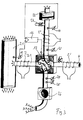
- FIG. 3 an arrangement is shown which serves to provide measurement gas which is free of volatile suspended particles and whose concentration of suspended solid particles is proportional to the suspended particle quantity in a raw gas channel.
- the arrangement combines principles of the two aspects of the invention outlined above.
- a Rohgaskanal 21 is via a secondary Rohgaskanal 31 with the help a branched off 26 raw gas.
- On a first Schusset 2 this is heated and then diluted.
- the dilution is done here via a Carousel thinner 13 in a sample gas channel, in which - in the figure in the upper arm of the channel - diluent gas flows in.
- a particle filter 22 can upstream to ensure that the diluent gas is floating particle-free is.
- the carousel thinner 13 is a second Heating section 2 'downstream.
- the first and second Schusumble 2, 2 'can cooperate so that the desired temperature for volatilization (For example, between 180 ° C and 400 ° C) only in or after the second Schusumble 2 ' is reached, so the first Schusumble therefore serves as preheating, for example.
- the desired temperature for volatilization For example, between 180 ° C and 400 ° C
- a dilution gas pre-pass for example, 2 may serve to dilute the gas to about the same Preheat temperature as the raw gas.
- the temperature of the raw gas and the Diluent gas before the second heating section 2 ' is, for example, between 70 ° C and 160 ° C.
- the controller 12 controls the supply of raw gas into the sample gas channel. 4 For example, so that the sample gas channel 4 per Zeiteinhat supplied amount of raw gas proportional to the volume flow in the raw gas duct 21 and, depending on the also Dilution gas volume flow in the sample gas channel is; the latter is replaced by a second measuring probe 14 determined. Further probes 23, 24, 25 serve the Temperature and pressure determination of the gases in the measuring and secondary raw gas ducts; the values determined with these probes can also be converted into the controller 12 caused regulation (not shown).
- the secondary raw gas channel With Korean amount of raw gas is in many cases irrelevant and can be neglected. But it can also be a corresponding Correction be made, for example, the pump 26 is often a well-known Promote volume per unit of time; also pressure and temperature measurements with Measuring probes 24, 25 can provide information for this purpose.
- the first measuring probe 11 mounted before the branch of the secondary raw gas duct be.
- a diluent gas can - as in all other embodiments - any one Gas to be used.
- it should be substantially no suspended particles have, i. the suspended particle concentration should be much lower than that of the raw gas. It will often be convenient to use filtered air as a diluent gas to use.
- measuring units can be used for characterization connect the aerosol present in the sample gas channel. These can be on based on different physical principles and physical and chemical Characterize the properties of suspended particles. For example, you can Light scattering on the particles, the electrical charge diffused on the particles, the photoelectric yield, the mobility, etc. or the particle mass to be analyzed. There can be several different measurement units in parallel switched or possibly arranged in series one behind the other; a combination of different physical principles increases the Significance of the measurements.
- a particularly preferred example of a Measuring unit, which can then be arranged on the sample gas channel is a condensation nucleus counter according to the third described below Aspect of the invention:
- FIG. 4 schematically shows a condensation nucleus counter for counting suspended particles.
- Condensation core counters are known per se; Therefore, the apparatus details and the operation of the Kondentsationskernippoers are described here only in summary. It is understood that the third aspect of the invention can be combined with any known or new condensation core meter design.
- a certain, generally small (for example, approximately 1 1 / min) amount of sample gas is diverted from the sample gas channel 4 (any existing pumps, chokes, control means, etc.
- the sample gas is heated by a heated saturator 41 (temperature for example, about 35 ° C) steered; in this case, for example, it comes into contact with a butanol-impregnated sponge (of course, other volatile substances are conceivable instead of butanol). It is then passed through a condenser 43 (temperature: for example, about 10 ° C.) provided with coolants 42, where the butanol present in supersaturation at the prevailing temperatures condenses out on the surface of the suspended particles. Due to the above-mentioned restrictions but that is only the case for suspended particles with a certain minimum radius in sufficient measure.
- the measuring gas passes through an outlet nozzle 44 into a measuring chamber, in which a light beam 47 generated by a light source 45-typically a laser diode-is focused onto a measuring volume lying immediately behind the outlet opening of the outlet nozzle 44.
- Butanol droplets (with a suspended particle as the condensation core) scattered light passes via focusing means 46 to a photodetector 49; unscattered light is absorbed by a shutter 48.
- Light pulses generated by the photodetector arrive in an evaluation unit 50.
- the evaluation unit 50 - may comprise means for analog and / or digital electronic amplification, processing and / or conversion of signals and electronic data processing means - an evaluation according to scattered light intensities. It has been found that such an evaluation provides indications of the reliability of the measurement. For illustration, two diagrams are shown in FIGS. 5a and 5b which, for different situations, represent the frequency (C) of the measurement pulses determined during a certain measurement duration as a function of the pulse strength (I) (the diagrams are thus actually histograms). The pulse strength I depends on the particle size. Very small pulse intensities correspond to particles on whose surface not enough condensate could accumulate.
- I th represents the threshold intensity below which no or no reliable measurement results can be determined.
- 61 denotes the measured curve, 62 the frequency distribution in the no longer measurable range below the threshold intensity, which is therefore inaccessible in practice. Pulses whose intensity is below the threshold intensity are not counted during a count.
- FIG. 5a represents the normal case. From the course of the measured frequency distribution 61, it can be concluded with rather great reliability that the frequency of the non-measurable pulses (represented by the dotted line 62) is small. In a case such as in Fig. 5b, where the measured frequency distribution 61 coming from large intensities does not substantially decrease towards I th or even increases, this is not the case. Here one must reckon with a high frequency in the non-measurable range. Accordingly, a measurement result which counts only the measurable range pulses (as in Fig. 5b) can not be used. It is to be rejected.
- the distinction as to whether a measurement result is useful or needs to be discarded can be made in different ways based on the frequency distribution (as a function of the pulse strength). For example, the frequency of pulses measured at a certain intensity interval I above the threshold can be determined and set in relation to the measured total intensity. If the proportion of pulses measured in the intensity interval I exceeds a certain adjustable percentage, the measurement is discarded. Alternatively, the slope of the C (I) curve near I th may also be determined, and the measurement may be discarded, for example, if it is negative, or the maximum of the C (I) curve may be at the value I th are compared etc.
- the device accordingly comprises means for electronic analysis of the frequency distribution, so that due to the Frequency distribution Inferences on the frequency of particles below the one certain threshold size can be made.
- a first aspect of the invention are volatile Suspended airborne particles, in a first step, the aerosol on a Temperature is heated, at which the volatile suspended particles evaporate and in a second step diluting the aerosol with a diluent gas.
- the order of the first and second steps can be reversed.
- a dilution of the raw gas takes place so that Raw gas is supplied to a sample gas flowing through the sample gas channel, wherein the per unit of time transferred amount of raw gas is dependent on the flow rate in the Raw gas.
- a third aspect of the invention is in a Condensation core counter not only the number of measured scattered light pulses but also evaluated their intensity to make statements about the reliability of the To be able to measure.
- Units for realizing the first, second and third aspects can be combined, which brings beneficial results. Such units but can also, alternatively or additionally, with further methods and Devices for Characterizing, Separating or Eliminating Aerosols - According to the prior art or newly developed - combined.
- a combination of the first and third aspects of the invention is advantageous in terms of reliable measurements of the particle number only the solid Suspended particles or a combination of the first and second aspects of Invention or the second and third aspects relating to the reduction of the scope and energy consumption of a plant for measuring harmful Suspended particles.
Landscapes
- Health & Medical Sciences (AREA)
- Chemical & Material Sciences (AREA)
- Life Sciences & Earth Sciences (AREA)
- Biochemistry (AREA)
- Physics & Mathematics (AREA)
- Analytical Chemistry (AREA)
- General Health & Medical Sciences (AREA)
- General Physics & Mathematics (AREA)
- Immunology (AREA)
- Pathology (AREA)
- Dispersion Chemistry (AREA)
- Engineering & Computer Science (AREA)
- Biomedical Technology (AREA)
- Molecular Biology (AREA)
- Sampling And Sample Adjustment (AREA)
Abstract
Description
- der Zeitversatz zwischen der Volumenstrommessung im Abgasstrang und dem Eintreffen der entsprechenden Partikelwolke im Messinstrument,
- die diffusionsbedingte Verschmierung der (Flanken der) Partikelwolke auf dem Transportweg zum Messinstrument,
- das Ansprechverhalten des im Instrument realisierten Messprinzips auf eine sich schnell ändernde Partikelkonzentration.
- die Figuren 1a und 1b je ein Schema von Ausführungsformen des ersten Aspekts der Erfindung,
- die Figur 2 ein Schema einer Ausführungsform des zweiten Aspekts der Erfindung,
- die Figur 3 ein Schema einer Anordnung zum Bereitstellen von Messgas, welches frei von flüchtigen Schwebeteilchen ist und dessen Konzentration an festen Schwebeteilchen proportional zur Schwebeteilchenmenge in einem Rohgaskanal ist,
- die Figur 4 ein Schema einer Ausführungsform des dritten Aspektes der Erfindung,
- die Figuren 5a und 5b fiktive Häufigkeitsverteilungen von Streulichpulsen in Funktion von deren Intensität.
- Beispielsweise muss das in den Rohgaskanal 1 eingeleitete Gas nicht das gesamte bspw. als Verbrennungsabgas erhaltene Rohgas sein; vielmehr kann auch nur ein Teil dieses Gases verwendet werden.
- Die in den Verdünnungsgaskanal 3 eingeleitete Gasmenge kann geregelt sein, bspw. so, dass die im Messgaskanal 4 fliessende Gasmenge immer konstant ist.
- Abweichend vom Prinzip der Vollstromverdünnung kann auch nur ein Teil des Rohgases zusammen mit Verdünnungsgas einem Messgaskanal zugeführt werden. Dazu folgt weiter unten noch ein Beispiel, dort in Kombination mit dem zweiten Aspekt der Erfindung.
Claims (14)
- Verfahren zum Charakterisieren, Trennen und/oder Eliminieren von Schwebeteilchen in einem Trägergas eines Aerosols, wobei das Aerosol flüchtige Schwebeteilchen enthält, mit den folgenden, in beliebiger Reihenfolge auszuführenden Verfahrensschritten:Aufheizen des Aerosols auf eine Temperatur, bei welcher die flüchtigen Schwebeteilchen verdampfenVerdünnen des Aerosols mit einem Verdünnungsgas.
- Verfahren nach Anspruch 1, dadurch gekennzeichnet, dass das Aerosol auf eine Temperatur von mindestens 180°C und vorzugsweise zwischen 200°C und 400°C aufgeheizt wird.
- Vorrichtung zur Durchführung des Verfahrens nach Anspruch 1 oder 2, aufweisend eine Gaszuführung und eine Gasableitung gekennzeichnet durch Beheizungsmittel zum Beheizen des Aerosols auf eine Temperatur, bei welcher flüchtige Schwebeteilchen verdampfen und durch eine Verdünnungseinheit (13) zum Verdünnen des Aerosols mit einem Verdünnungsgas.
- Vorrichtung nach Anspruch 3, dadurch gekennzeichnet, dass die Verdünnungseinheit den Beheizungsmittel in Flussrichtung des Aerosols nachgeschaltet ist.
- Vorrichtung nach Anspruch 3, dadurch gekennzeichnet, dass die Verdünnungseinheit in Flussrichtung des Aerosols den Beheizungsmitteln vorgeschaltet ist.
- Vorrichtung nach einem der Ansprüche 3 bis 5, dadurch gekennzeichnet, dass die Beheizungsmittel so ausgebildet sind, dass sie in einem Normalbetrieb das Aerosol auf eine Temperatur von mindestens 180°C und vorzugsweise zwischen 200°C und 400°C aufheizen.
- Verfahren zum Charakterisieren, Trennen und/oder Eliminieren von Schwebeteilchen in einem Trägergas eines Aerosols, insbesondere nach Anspruch 1 oder 2, wobei in einem Rohgaskanal (1) mit zu charakterisierendem Rohgas ein zeitlich nicht konstanter Volumenstrom vorhanden ist und wobei ein Messgaskanal (4) zum Zuführen von Messgas zu mindestens einer Messeinheit vorhanden ist, aufweisend die folgenden Verfahrensschritte:wobei der Transfer so geregelt wird, dass die pro Zeiteinheit transferierte Rohgasmenge abhängig vom Volumenstrom im Rohgaskanal (1, 21) und desto grösser ist, je grösser der Volumenstrom im Rohgaskanal ist.Durchfliessen des Messgaskanals (4) mit einem VerdünnungsgasErmitteln des Volumenstroms im Rohgaskanal (1, 21)Transfer von Rohgas aus dem Rohgaskanal (1, 21) in den Messgaskanal,
- Verfahren nach Anspruch 7, dadurch gekennzeichnet, dass die pro Zeiteinheit transferierte Rohgasmenge, bis auf einen möglichen Zeitversatz proportional zum Volumenstrom im Rohgaskanal (1, 21) ist.
- Verfahren nach Anspruch 7 oder 8, dadurch gekennzeichnet, dass auch der Volumenstrom im Messgaskanal ermittelt wird, und dass die pro Zeiteinheit aus dem Rohgaskanal in den Messgaskanal transferierte Rohgasmenge desto grösser ist, je grösser der Volumenstrom im Messgaskanal ist.
- Verfahren nach Anspruch 9, dadurch gekennzeichnet, dass die pro Zeiteinheit transferierte Rohgasmenge bis auf einen möglichen Zeitversatz proportional zum Volumenstrom im Messgaskanal ist
- Vorrichtung, insbesondere nach einem der Ansprüche 3 bis 6, zum Durchführen des Verfahrens nach einem der Ansprüche 7 bis 10, aufweisend einen Rohgaskanal mit einem Aerosol-Einlass, und einen Messgaskanal mit einem Verdünnungsgaseinlass sowie mit Transfermitteln (13) zum dosierten Transfer von Aerosol aus dem Rohgaskanal in den Messgaskanal, gekennzeichnet durch Mittel zum Bestimmen des Aerosol-Durchflusses im Rohgaskanal und einen Regler (12) zum Regeln des Transfers von Rohgas in den Messgaskanal, wobei der Regler so ausgebildet ist und so mit den Transfermitteln in Wirkverbindung steht, dass die Transfermittel desto mehr Rohgas transferieren, je höher der Rohgas-Volumenstrom im Rohgaskanal ist.
- Verfahren zum Charakterisieren, Trennen und/oder Eliminieren von Schwebeteilchen in einem Trägergas eines Aerosols, insbesondere nach einem der Ansprüche 1, 2 oder 7 bis 10, wobei mindestens ein Teil des Aerosols mit dem Dampf einer flüchtigen Substanz in Übersättigung versehen wird, wodurch die flüchtige Substanz an der Oberfläche von Schwebeteilchen auskondensiert, wodurch Tröpfchen entstehen, und wobei anschliessend die Tröpfchen durch einen Lichtstrahl gelenkt werden und dadurch einen Streulichtpuls verursachen, welcher zum Zählen der Tröpfchen detektiert wird dadurch gekennzeichnet, dass eine Streulichtpulsintensität detektiert und ausgewertet wird.
- Verfahren nach Anspruch 12, dadurch gekennzeichnet, dass der Anteil von Streulichtpulsen mit niedrigen Intensitäten nahe einer Streulichtpuls-Detektionsschwelle an der Menge aller detektierten Streulichtpulse ermittelt wird.
- Vorrichtung, insbesondere nach einem der Ansprüche 3 bis 6 oder 11 zur Durchführung des Verfahrens nach Anspruch 12 oder 13, aufweisend einen Sättiger (41) in welchem Aerosol mit einer flüchtigen Substanz versehen werden kann und einen Kondenser (43) in welchem Bedingungen vorherrschen, durch welche die flüchtige Substanz in Übersättigung bringbar ist, ein Messvolumen, in welchem Schwebeteilchen aus dem Kondenser durch einen Lichtstrahl lenkbar sind, und Detektionsmittel zum Detektieren von Streulichtpulsen, welche durch das Streuen von Licht des Lichtstrahles an Schwebeteilchen verursacht wird, gekennzeichnet durch Auswertemittel, die zur Auswertung von Streulichtpulsintensitäten ausgebildet sind.
Priority Applications (6)
| Application Number | Priority Date | Filing Date | Title |
|---|---|---|---|
| ES03405248T ES2550347T5 (es) | 2003-04-11 | 2003-04-11 | Procedimiento y dispositivo para la detección, caracterización y/o eliminación de partículas en suspensión |
| EP03405248.0A EP1467194B2 (de) | 2003-04-11 | 2003-04-11 | Verfahren und Vorrichtung zur Detektion, Charakterisierung und/oder Elimination von Schwebeteilchen |
| EP10010663.2A EP2270465B2 (de) | 2003-04-11 | 2003-04-11 | Verfahren und Vorrichtung zur Detektion, Charakterisierung und/oder Elimination von Schwebeteilchen |
| JP2004111857A JP4939734B2 (ja) | 2003-04-11 | 2004-04-06 | 浮遊粒子の検出、特性化及び/又は除去をするための方法及び装置 |
| US10/819,832 US7682426B2 (en) | 2003-04-11 | 2004-04-07 | Method and device for the detection, characterization and/or elimination of suspended particles |
| US11/463,124 US7427311B2 (en) | 2003-04-11 | 2006-08-08 | Method and device for the detection, characterization and/or elimination of suspended particles |
Applications Claiming Priority (1)
| Application Number | Priority Date | Filing Date | Title |
|---|---|---|---|
| EP03405248.0A EP1467194B2 (de) | 2003-04-11 | 2003-04-11 | Verfahren und Vorrichtung zur Detektion, Charakterisierung und/oder Elimination von Schwebeteilchen |
Related Child Applications (2)
| Application Number | Title | Priority Date | Filing Date |
|---|---|---|---|
| EP10010663.2A Division EP2270465B2 (de) | 2003-04-11 | 2003-04-11 | Verfahren und Vorrichtung zur Detektion, Charakterisierung und/oder Elimination von Schwebeteilchen |
| EP10010663.2A Division-Into EP2270465B2 (de) | 2003-04-11 | 2003-04-11 | Verfahren und Vorrichtung zur Detektion, Charakterisierung und/oder Elimination von Schwebeteilchen |
Publications (3)
| Publication Number | Publication Date |
|---|---|
| EP1467194A1 true EP1467194A1 (de) | 2004-10-13 |
| EP1467194B1 EP1467194B1 (de) | 2015-08-19 |
| EP1467194B2 EP1467194B2 (de) | 2021-11-03 |
Family
ID=32865102
Family Applications (2)
| Application Number | Title | Priority Date | Filing Date |
|---|---|---|---|
| EP03405248.0A Expired - Lifetime EP1467194B2 (de) | 2003-04-11 | 2003-04-11 | Verfahren und Vorrichtung zur Detektion, Charakterisierung und/oder Elimination von Schwebeteilchen |
| EP10010663.2A Expired - Lifetime EP2270465B2 (de) | 2003-04-11 | 2003-04-11 | Verfahren und Vorrichtung zur Detektion, Charakterisierung und/oder Elimination von Schwebeteilchen |
Family Applications After (1)
| Application Number | Title | Priority Date | Filing Date |
|---|---|---|---|
| EP10010663.2A Expired - Lifetime EP2270465B2 (de) | 2003-04-11 | 2003-04-11 | Verfahren und Vorrichtung zur Detektion, Charakterisierung und/oder Elimination von Schwebeteilchen |
Country Status (4)
| Country | Link |
|---|---|
| US (2) | US7682426B2 (de) |
| EP (2) | EP1467194B2 (de) |
| JP (1) | JP4939734B2 (de) |
| ES (1) | ES2550347T5 (de) |
Cited By (5)
| Publication number | Priority date | Publication date | Assignee | Title |
|---|---|---|---|---|
| WO2012123077A1 (de) * | 2011-03-11 | 2012-09-20 | Testo Ag | Handgehaltener probenentnahmekopf, analyseanordnung und verfahren zur charakterisierung eines aerosols |
| DE102012003518A1 (de) * | 2012-02-24 | 2013-08-29 | Deutsches Zentrum für Luft- und Raumfahrt e.V. | Heizungsvorrichtung eines Thermodenuders |
| CN110132802A (zh) * | 2019-05-07 | 2019-08-16 | 张家港谱析传感科技有限公司 | 一种粒径及粒子浓度在线检测装置及在线检测方法 |
| CN114441269A (zh) * | 2022-02-14 | 2022-05-06 | 华北电力大学(保定) | 一种大气气溶胶的成分与数量检测装置 |
| US11480475B2 (en) * | 2019-07-03 | 2022-10-25 | Pratt & Whitney Canada Corp. | Method and system for measuring temperature in a gas turbine engine |
Families Citing this family (20)
| Publication number | Priority date | Publication date | Assignee | Title |
|---|---|---|---|---|
| JP2006194726A (ja) * | 2005-01-13 | 2006-07-27 | Mazda Motor Corp | Pm粒子数計測装置 |
| US7387038B2 (en) * | 2005-07-29 | 2008-06-17 | Horiba Instruments, Inc. | Wide range constant concentration particle generating system |
| NL2000048C2 (nl) * | 2006-04-07 | 2007-10-09 | Univ Eindhoven Tech | Werkwijze en inrichting voor het reduceren van de vorming van partikels in een gasstroom. |
| US7587950B2 (en) * | 2006-09-11 | 2009-09-15 | Cummins Filtration Ip Inc. | Source dilution sampling system for emissions analysis |
| JPWO2008146735A1 (ja) * | 2007-05-23 | 2010-08-19 | アエモテック株式会社 | 繊維状粒子除去装置 |
| US8136034B2 (en) * | 2007-12-18 | 2012-03-13 | Aaron Stanton | System and method for analyzing and categorizing text |
| GB0806210D0 (en) * | 2008-04-04 | 2008-05-14 | Univ Aston | Sampling of fluids for analysis |
| US8465791B2 (en) * | 2009-10-16 | 2013-06-18 | Msp Corporation | Method for counting particles in a gas |
| DE102010002423A1 (de) * | 2010-02-26 | 2011-09-01 | Robert Bosch Gmbh | Vorrichtung und Verfahren zum Kalibrieren eines Streulichtmessgerätes |
| DE102011002421A1 (de) * | 2011-01-04 | 2012-07-05 | Robert Bosch Gmbh | Messgerät zur Messung von Partikelkonzentrationen mittels Streulicht und Verfahren zur Überwachung des Messgerätes |
| US8771402B2 (en) * | 2011-06-14 | 2014-07-08 | Ut-Battelle, Llc | Membrane based apparatus for measurement of volatile particles |
| AT509962B1 (de) | 2011-09-12 | 2015-05-15 | Avl List Gmbh | Verfahren und vorrichtung zur ermittlung der konzentration von aerosolen in heissen gasen, insbesondere in abgasen von verbrennungskraftmaschinen |
| US10145269B2 (en) | 2015-03-04 | 2018-12-04 | General Electric Company | System and method for cooling discharge flow |
| GB2542827B (en) * | 2015-09-30 | 2019-10-02 | Smiths Detection Watford Ltd | Sampling method and apparatus with heating to vapourise components |
| EP4560288A3 (de) | 2016-04-01 | 2025-08-20 | TSI Incorporated | Verringerung von falschzählungen bei kondensationspartikelzählern |
| CN106383071B (zh) * | 2016-08-19 | 2019-04-09 | 上海电力学院 | 一种固体颗粒系高温热辐射特性测量装置 |
| DE102017008705A1 (de) | 2017-09-18 | 2019-03-21 | Technische Universität Ilmenau | Vorrichtung zur Ermittlung von Quantitäten und Qualitäten von Emissionen einer Bearbeitungszone einer Fertigungsmaschine |
| KR102199628B1 (ko) * | 2020-01-23 | 2021-01-08 | 주식회사 정엔지니어링 | 응축성 미세먼지를 포함하는 굴뚝 미세먼지의 연속측정장치 및 유해중금속을 포함하는 다이옥신 연속포집장치 |
| US11828696B2 (en) | 2020-12-16 | 2023-11-28 | Caterpillar Inc. | System and method for processing data from a particle monitoring sensor |
| CN114002115B (zh) * | 2021-10-20 | 2022-06-14 | 江苏愈厚环保科技有限公司 | 一种自加热再生型激光散射法颗粒物传感器 |
Citations (3)
| Publication number | Priority date | Publication date | Assignee | Title |
|---|---|---|---|---|
| WO2001084116A1 (de) | 2000-05-02 | 2001-11-08 | Dr. Födisch Umweltmeßtechnik GmbH | Verfahren und einrichtung zur extraktiven triboelektrischen staub- und aerosolmessung in strömenden gasen |
| US6439027B1 (en) * | 2000-08-10 | 2002-08-27 | Rupprecht & Patashnick Company, Inc. | Particulate mass measurement apparatus with real-time moisture monitor |
| EP1251344A2 (de) * | 2001-04-18 | 2002-10-23 | AVL List GmbH | Verfahren zur Messung von Aerosolteilchen in gasförmigen Proben |
Family Cites Families (30)
| Publication number | Priority date | Publication date | Assignee | Title |
|---|---|---|---|---|
| DE1598288C3 (de) * | 1965-11-06 | 1974-10-03 | Ceskoslovenska Akademie Ved, Prag | Verfahren und Vorrichtung zur Analyse von dispersen Systemen |
| JPS59206741A (ja) * | 1983-05-11 | 1984-11-22 | Mitsubishi Heavy Ind Ltd | 固気混相流体の希釈方法および装置 |
| US4586367A (en) † | 1984-03-19 | 1986-05-06 | Horiba Instruments Incorporated | Proportional exhaust sampler and control means |
| JPH0676961B2 (ja) * | 1986-02-28 | 1994-09-28 | 日野自動車工業株式会社 | 粒子状物質測定装置 |
| JPH0663961B2 (ja) * | 1986-03-24 | 1994-08-22 | 日本科学工業株式会社 | 液中不純物測定方法とその測定装置 |
| JPH01195341A (ja) * | 1988-01-29 | 1989-08-07 | Hitachi Electron Eng Co Ltd | 超純水中の微粒子の測定装置 |
| US5109708A (en) | 1989-03-15 | 1992-05-05 | E. I. Du Pont De Nemours And Company | Sampling system and method for sampling concentrated aerosols |
| DE58903466D1 (de) | 1989-04-01 | 1993-03-18 | Kugelfischer G Schaefer & Co | Sonde zur entnahme von aggressiven gasen aus kanaelen, insbesondere rauchgaskanaelen. |
| US5026155A (en) * | 1989-09-06 | 1991-06-25 | Air Products And Chemicals, Inc. | Process for sizing particles using condensation nucleus counting |
| AT393173B (de) | 1990-08-14 | 1991-08-26 | Steyr Nutzfahrzeuge | Anlage zur schadstoffanalyse, insbesondere partikelemission, von dieselmotorenabgas, mit einer speziellen teilstromverduennungseinrichtung |
| US5058440A (en) | 1990-09-04 | 1991-10-22 | Caterpillar Inc. | Gas sampling device and dilution tunnel used therewith |
| DE4134665A1 (de) * | 1991-10-19 | 1993-04-22 | Solvay Deutschland | Medizinisches inhalationssystem |
| JP3171633B2 (ja) * | 1992-01-31 | 2001-05-28 | 野村マイクロ・サイエンス株式会社 | 超純水中の不揮発性不純物の分析および定量方法 |
| IT1260889B (it) † | 1993-02-19 | 1996-04-29 | Iveco Fiat | Metodo ed apparecchiatura per il prelievo di particolato dai gas di scarico di motori diesel. |
| DE4437739A1 (de) | 1994-10-21 | 1996-04-25 | Siemens Ag | Verfahren und Anordnung zum Aufbereiten von Abgas, insbesondere von Verbrennungsmotoren für die Analyse |
| JP3523354B2 (ja) * | 1995-01-14 | 2004-04-26 | 株式会社堀場製作所 | 連続パーティキュレート測定装置 |
| US6200819B1 (en) | 1995-09-29 | 2001-03-13 | Horiba Instruments, Inc. | Method and apparatus for providing diluent gas to exhaust emission analyzer |
| US6435004B1 (en) * | 1997-09-12 | 2002-08-20 | Nicholas C. Miller | Apparatus and process for aerosol size measurement at varying gas flow rates |
| US6016711A (en) † | 1997-11-21 | 2000-01-25 | Southwest Research Institute | Mobile vehicle emissions sampling system |
| DE69917594T2 (de) | 1998-01-05 | 2005-06-23 | United States Environmental Protection Agency | Modularer echtzeit- abgas-durchflussmesser für fahrende fahrzeuge und berichtsystem für emissionen |
| US6306954B1 (en) † | 1998-01-12 | 2001-10-23 | Sumitomo Electric Industries, Ltd. | Adhesive resin composition and heat-shrinkable articles made by using the same |
| JPH11211631A (ja) | 1998-01-21 | 1999-08-06 | Tsukasa Sokken:Kk | 排気ガス希釈サンプリング装置 |
| JP2001188031A (ja) | 1999-10-18 | 2001-07-10 | Firmware Technology Co Ltd | 排気ガス中の粒子状物質の測定方法および測定装置 |
| JP2001249065A (ja) | 1999-12-28 | 2001-09-14 | Ono Sokki Co Ltd | 排出ガス希釈装置 |
| AU2001259244A1 (en) | 2000-04-28 | 2001-11-12 | Pp And L Resources, Inc. | Emission monitoring system and method |
| JP2002214082A (ja) | 2001-01-24 | 2002-07-31 | Tsukasa Sokken Co Ltd | 排気ガス流量とガス組成の高速連続測定によるマスエミッシヨンまたは燃料消費量計測における同時性を確保する同時性補正装置 |
| AUPR348001A0 (en) | 2001-03-02 | 2001-03-29 | Parsons Australia Pty Ltd | Assembly and method for mixing gases |
| DE60209466T2 (de) | 2001-04-13 | 2006-08-24 | Avl List Gmbh | Aktive Druckschwingungsdämpfer zur Probenentnahme von Teilchen aus Dieselmotoren |
| JP2003075308A (ja) † | 2001-09-06 | 2003-03-12 | Tsukasa Sokken Co Ltd | ミニ・定流量サンプリング装置 |
| WO2003035206A2 (en) | 2001-10-22 | 2003-05-01 | Sensors, Inc. | Vehicle particulate analysis method and apparatus |
-
2003
- 2003-04-11 EP EP03405248.0A patent/EP1467194B2/de not_active Expired - Lifetime
- 2003-04-11 ES ES03405248T patent/ES2550347T5/es not_active Expired - Lifetime
- 2003-04-11 EP EP10010663.2A patent/EP2270465B2/de not_active Expired - Lifetime
-
2004
- 2004-04-06 JP JP2004111857A patent/JP4939734B2/ja not_active Expired - Lifetime
- 2004-04-07 US US10/819,832 patent/US7682426B2/en active Active
-
2006
- 2006-08-08 US US11/463,124 patent/US7427311B2/en not_active Expired - Fee Related
Patent Citations (3)
| Publication number | Priority date | Publication date | Assignee | Title |
|---|---|---|---|---|
| WO2001084116A1 (de) | 2000-05-02 | 2001-11-08 | Dr. Födisch Umweltmeßtechnik GmbH | Verfahren und einrichtung zur extraktiven triboelektrischen staub- und aerosolmessung in strömenden gasen |
| US6439027B1 (en) * | 2000-08-10 | 2002-08-27 | Rupprecht & Patashnick Company, Inc. | Particulate mass measurement apparatus with real-time moisture monitor |
| EP1251344A2 (de) * | 2001-04-18 | 2002-10-23 | AVL List GmbH | Verfahren zur Messung von Aerosolteilchen in gasförmigen Proben |
Cited By (9)
| Publication number | Priority date | Publication date | Assignee | Title |
|---|---|---|---|---|
| WO2012123077A1 (de) * | 2011-03-11 | 2012-09-20 | Testo Ag | Handgehaltener probenentnahmekopf, analyseanordnung und verfahren zur charakterisierung eines aerosols |
| US9534991B2 (en) | 2011-03-11 | 2017-01-03 | Testo Ag | Handheld sampling-removal head, analysis arrangement and method for characterizing an aerosol |
| DE102012003518A1 (de) * | 2012-02-24 | 2013-08-29 | Deutsches Zentrum für Luft- und Raumfahrt e.V. | Heizungsvorrichtung eines Thermodenuders |
| DE102012003518B4 (de) * | 2012-02-24 | 2013-11-14 | Deutsches Zentrum für Luft- und Raumfahrt e.V. | Heizungsvorrichtung eines Thermodenuders |
| CN110132802A (zh) * | 2019-05-07 | 2019-08-16 | 张家港谱析传感科技有限公司 | 一种粒径及粒子浓度在线检测装置及在线检测方法 |
| CN110132802B (zh) * | 2019-05-07 | 2024-01-12 | 张家港谱析传感科技有限公司 | 一种粒径及粒子浓度在线检测装置及在线检测方法 |
| US11480475B2 (en) * | 2019-07-03 | 2022-10-25 | Pratt & Whitney Canada Corp. | Method and system for measuring temperature in a gas turbine engine |
| CN114441269A (zh) * | 2022-02-14 | 2022-05-06 | 华北电力大学(保定) | 一种大气气溶胶的成分与数量检测装置 |
| CN114441269B (zh) * | 2022-02-14 | 2023-08-08 | 华北电力大学(保定) | 一种大气气溶胶的成分与数量检测装置 |
Also Published As
| Publication number | Publication date |
|---|---|
| US7427311B2 (en) | 2008-09-23 |
| US7682426B2 (en) | 2010-03-23 |
| EP2270465A1 (de) | 2011-01-05 |
| EP2270465B2 (de) | 2016-06-29 |
| EP1467194B2 (de) | 2021-11-03 |
| EP1467194B1 (de) | 2015-08-19 |
| US20070006728A1 (en) | 2007-01-11 |
| ES2550347T3 (es) | 2015-11-06 |
| US20040202578A1 (en) | 2004-10-14 |
| JP2004354370A (ja) | 2004-12-16 |
| ES2550347T5 (es) | 2022-04-07 |
| JP4939734B2 (ja) | 2012-05-30 |
| EP2270465B1 (de) | 2012-06-27 |
Similar Documents
| Publication | Publication Date | Title |
|---|---|---|
| EP2270465B1 (de) | Verfahren und Vorrichtung zur Detektion, Charakterisierung und/oder Elimination von Schwebeteilchen | |
| DE112006001351B4 (de) | Instrumente zum Messen der Belastung durch Nanopartikel | |
| DE10307805B4 (de) | Weitbereich-Teilchenzähler | |
| DE4107902C2 (de) | Vorrichtung zur In-Line-Analyse der Partikelgrößenverteilung in Abgasen | |
| DE69922970T2 (de) | Verfahren und vorrichtung zum zählen von pollenkörnern | |
| EP1681550A1 (de) | Verfahren und Vorrichtung zur Messung von Anzahlkonzentration und mittlerem Durchmesser von Aerosolpartikeln | |
| DE102009055023B4 (de) | Vorrichtung zur Messung der Massenkonzentration von im Abgas von Feststoffverbrennungsvorrichtungen vorhandenem Feinstaub | |
| EP1477801A1 (de) | Verfahren und Vorrichtung zur Abgasmessung von Verbrennungskraftmaschinen | |
| DE2411968A1 (de) | Verfahren und vorrichtung zur geochemischen erkundung eines bodenbereichs | |
| DE19983372B4 (de) | Gasmischsystem und Verfahren | |
| DE10137106A1 (de) | Einrichtung zur Probenahme von Abgas | |
| WO2020038658A1 (de) | Partikelmesssystem mit einer verdünnungsvorrichtung und verfahren zur partikelmessung | |
| WO2011050932A1 (de) | Messgerät zur abgasmessung einer partikelmassekonzentrationen in einem messgas, insbesondere in einem verbrennungsabgas | |
| DE3923453C2 (de) | Verfahren und Vorrichtung zum Messen eines kondensierbare Bestandteile, Flüssigkeitsnebel u. dgl. enthaltenden Gasstrom | |
| DE102008009494A1 (de) | Vorrichtung zur Erfassung der Konzentration und/oder der Größenverteilung von elektrisch geladenen Partikeln in Gasströmen, insbesondere von Rußpartikeln in Dieselabgasen | |
| EP0632263B1 (de) | Verfahren zur Untersuchung eines Gases | |
| EP3112845B1 (de) | Vorrichtung zur optischen in-situ analyse eines messgases | |
| DE102012211538B4 (de) | Verfahren und System zum Nachweisen von in einem Aerosol schwebenden Kohlenstoffnanoröhren | |
| EP2264429B1 (de) | Verfahren und Vorrichtung zum Bestimmen einer Elementarkohlenstoff-Gesamtmenge in einem Aerosol mittels Messung einer mittleren Partikelgrösse und einer Gesamtladung der Aerosolpartikel | |
| DE102008010764A1 (de) | Vorrichtung und Verfahren zur Staubdetektion | |
| AT524348B1 (de) | Verfahren und Vorrichtung zur Partikelmessung | |
| DE102020002041A1 (de) | Verfahren und Vorrichtung zum Bestimmen von Partikeln eines Aerosols | |
| DE102006032906B4 (de) | Vorrichtung und Verfahren zur Erfassung und Bewertung von Partikeln in einem Gasstrom | |
| DE10049125C2 (de) | Verfahren zum Messen von Partikeln in Gasströmen und Partikelsensoranordnung zur Durchführung des Verfahrens | |
| EP1685912A2 (de) | Messvorrichtung zur Bestimmung des Staubungsverhaltens von dispersen Systemen |
Legal Events
| Date | Code | Title | Description |
|---|---|---|---|
| PUAI | Public reference made under article 153(3) epc to a published international application that has entered the european phase |
Free format text: ORIGINAL CODE: 0009012 |
|
| AK | Designated contracting states |
Kind code of ref document: A1 Designated state(s): AT BE BG CH CY CZ DE DK EE ES FI FR GB GR HU IE IT LI LU MC NL PT RO SE SI SK TR |
|
| AX | Request for extension of the european patent |
Extension state: AL LT LV MK |
|
| 17P | Request for examination filed |
Effective date: 20050329 |
|
| AKX | Designation fees paid |
Designated state(s): AT BE BG CH CY CZ DE DK EE ES FI FR GB GR HU IE IT LI LU MC NL PT RO SE SI SK TR |
|
| 17Q | First examination report despatched |
Effective date: 20080318 |
|
| APBK | Appeal reference recorded |
Free format text: ORIGINAL CODE: EPIDOSNREFNE |
|
| APBN | Date of receipt of notice of appeal recorded |
Free format text: ORIGINAL CODE: EPIDOSNNOA2E |
|
| APBR | Date of receipt of statement of grounds of appeal recorded |
Free format text: ORIGINAL CODE: EPIDOSNNOA3E |
|
| APAF | Appeal reference modified |
Free format text: ORIGINAL CODE: EPIDOSCREFNE |
|
| APBT | Appeal procedure closed |
Free format text: ORIGINAL CODE: EPIDOSNNOA9E |
|
| RAP1 | Party data changed (applicant data changed or rights of an application transferred) |
Owner name: MATTER AEROSOL AG |
|
| REG | Reference to a national code |
Ref country code: DE Ref legal event code: R079 Ref document number: 50315324 Country of ref document: DE Free format text: PREVIOUS MAIN CLASS: G01N0001220000 Ipc: G01N0015000000 |
|
| GRAP | Despatch of communication of intention to grant a patent |
Free format text: ORIGINAL CODE: EPIDOSNIGR1 |
|
| INTG | Intention to grant announced |
Effective date: 20131113 |
|
| RIC1 | Information provided on ipc code assigned before grant |
Ipc: G01N 1/22 20060101ALI20131104BHEP Ipc: G01N 15/06 20060101ALI20131104BHEP Ipc: G01N 15/00 20060101AFI20131104BHEP Ipc: G01N 1/38 20060101ALI20131104BHEP Ipc: G01N 15/14 20060101ALI20131104BHEP Ipc: G01N 1/24 20060101ALI20131104BHEP |
|
| GRAP | Despatch of communication of intention to grant a patent |
Free format text: ORIGINAL CODE: EPIDOSNIGR1 |
|
| INTG | Intention to grant announced |
Effective date: 20140725 |
|
| RAP1 | Party data changed (applicant data changed or rights of an application transferred) |
Owner name: TESTO AG |
|
| GRAS | Grant fee paid |
Free format text: ORIGINAL CODE: EPIDOSNIGR3 |
|
| GRAP | Despatch of communication of intention to grant a patent |
Free format text: ORIGINAL CODE: EPIDOSNIGR1 |
|
| INTG | Intention to grant announced |
Effective date: 20150608 |
|
| GRAA | (expected) grant |
Free format text: ORIGINAL CODE: 0009210 |
|
| AK | Designated contracting states |
Kind code of ref document: B1 Designated state(s): AT BE BG CH CY CZ DE DK EE ES FI FR GB GR HU IE IT LI LU MC NL PT RO SE SI SK TR |
|
| REG | Reference to a national code |
Ref country code: GB Ref legal event code: FG4D Free format text: NOT ENGLISH |
|
| REG | Reference to a national code |
Ref country code: CH Ref legal event code: EP |
|
| REG | Reference to a national code |
Ref country code: IE Ref legal event code: FG4D Free format text: LANGUAGE OF EP DOCUMENT: GERMAN |
|
| REG | Reference to a national code |
Ref country code: AT Ref legal event code: REF Ref document number: 744150 Country of ref document: AT Kind code of ref document: T Effective date: 20150915 |
|
| REG | Reference to a national code |
Ref country code: CH Ref legal event code: NV Representative=s name: GACHNANG AG PATENTANWAELTE, CH |
|
| REG | Reference to a national code |
Ref country code: DE Ref legal event code: R096 Ref document number: 50315324 Country of ref document: DE |
|
| REG | Reference to a national code |
Ref country code: ES Ref legal event code: FG2A Ref document number: 2550347 Country of ref document: ES Kind code of ref document: T3 Effective date: 20151106 |
|
| REG | Reference to a national code |
Ref country code: NL Ref legal event code: MP Effective date: 20150819 |
|
| PG25 | Lapsed in a contracting state [announced via postgrant information from national office to epo] |
Ref country code: GR Free format text: LAPSE BECAUSE OF FAILURE TO SUBMIT A TRANSLATION OF THE DESCRIPTION OR TO PAY THE FEE WITHIN THE PRESCRIBED TIME-LIMIT Effective date: 20151120 |
|
| PG25 | Lapsed in a contracting state [announced via postgrant information from national office to epo] |
Ref country code: PT Free format text: LAPSE BECAUSE OF FAILURE TO SUBMIT A TRANSLATION OF THE DESCRIPTION OR TO PAY THE FEE WITHIN THE PRESCRIBED TIME-LIMIT Effective date: 20151221 Ref country code: SE Free format text: LAPSE BECAUSE OF FAILURE TO SUBMIT A TRANSLATION OF THE DESCRIPTION OR TO PAY THE FEE WITHIN THE PRESCRIBED TIME-LIMIT Effective date: 20150819 |
|
| PG25 | Lapsed in a contracting state [announced via postgrant information from national office to epo] |
Ref country code: NL Free format text: LAPSE BECAUSE OF FAILURE TO SUBMIT A TRANSLATION OF THE DESCRIPTION OR TO PAY THE FEE WITHIN THE PRESCRIBED TIME-LIMIT Effective date: 20150819 |
|
| REG | Reference to a national code |
Ref country code: FR Ref legal event code: PLFP Year of fee payment: 14 |
|
| PG25 | Lapsed in a contracting state [announced via postgrant information from national office to epo] |
Ref country code: EE Free format text: LAPSE BECAUSE OF FAILURE TO SUBMIT A TRANSLATION OF THE DESCRIPTION OR TO PAY THE FEE WITHIN THE PRESCRIBED TIME-LIMIT Effective date: 20150819 Ref country code: DK Free format text: LAPSE BECAUSE OF FAILURE TO SUBMIT A TRANSLATION OF THE DESCRIPTION OR TO PAY THE FEE WITHIN THE PRESCRIBED TIME-LIMIT Effective date: 20150819 Ref country code: SK Free format text: LAPSE BECAUSE OF FAILURE TO SUBMIT A TRANSLATION OF THE DESCRIPTION OR TO PAY THE FEE WITHIN THE PRESCRIBED TIME-LIMIT Effective date: 20150819 Ref country code: CZ Free format text: LAPSE BECAUSE OF FAILURE TO SUBMIT A TRANSLATION OF THE DESCRIPTION OR TO PAY THE FEE WITHIN THE PRESCRIBED TIME-LIMIT Effective date: 20150819 |
|
| REG | Reference to a national code |
Ref country code: DE Ref legal event code: R026 Ref document number: 50315324 Country of ref document: DE |
|
| PLBI | Opposition filed |
Free format text: ORIGINAL CODE: 0009260 |
|
| PG25 | Lapsed in a contracting state [announced via postgrant information from national office to epo] |
Ref country code: RO Free format text: LAPSE BECAUSE OF FAILURE TO SUBMIT A TRANSLATION OF THE DESCRIPTION OR TO PAY THE FEE WITHIN THE PRESCRIBED TIME-LIMIT Effective date: 20150819 |
|
| PLAX | Notice of opposition and request to file observation + time limit sent |
Free format text: ORIGINAL CODE: EPIDOSNOBS2 |
|
| 26 | Opposition filed |
Opponent name: HORIBA, LTD. Effective date: 20160518 |
|
| PG25 | Lapsed in a contracting state [announced via postgrant information from national office to epo] |
Ref country code: SI Free format text: LAPSE BECAUSE OF FAILURE TO SUBMIT A TRANSLATION OF THE DESCRIPTION OR TO PAY THE FEE WITHIN THE PRESCRIBED TIME-LIMIT Effective date: 20150819 Ref country code: BE Free format text: LAPSE BECAUSE OF NON-PAYMENT OF DUE FEES Effective date: 20160430 |
|
| PLAF | Information modified related to communication of a notice of opposition and request to file observations + time limit |
Free format text: ORIGINAL CODE: EPIDOSCOBS2 |
|
| PLBB | Reply of patent proprietor to notice(s) of opposition received |
Free format text: ORIGINAL CODE: EPIDOSNOBS3 |
|
| PG25 | Lapsed in a contracting state [announced via postgrant information from national office to epo] |
Ref country code: LU Free format text: LAPSE BECAUSE OF FAILURE TO SUBMIT A TRANSLATION OF THE DESCRIPTION OR TO PAY THE FEE WITHIN THE PRESCRIBED TIME-LIMIT Effective date: 20160411 |
|
| REG | Reference to a national code |
Ref country code: IE Ref legal event code: MM4A |
|
| REG | Reference to a national code |
Ref country code: FR Ref legal event code: PLFP Year of fee payment: 15 |
|
| PG25 | Lapsed in a contracting state [announced via postgrant information from national office to epo] |
Ref country code: IE Free format text: LAPSE BECAUSE OF NON-PAYMENT OF DUE FEES Effective date: 20160411 |
|
| APBM | Appeal reference recorded |
Free format text: ORIGINAL CODE: EPIDOSNREFNO |
|
| APBP | Date of receipt of notice of appeal recorded |
Free format text: ORIGINAL CODE: EPIDOSNNOA2O |
|
| APAH | Appeal reference modified |
Free format text: ORIGINAL CODE: EPIDOSCREFNO |
|
| APAW | Appeal reference deleted |
Free format text: ORIGINAL CODE: EPIDOSDREFNO |
|
| APBQ | Date of receipt of statement of grounds of appeal recorded |
Free format text: ORIGINAL CODE: EPIDOSNNOA3O |
|
| RAP2 | Party data changed (patent owner data changed or rights of a patent transferred) |
Owner name: TESTO SE & CO. KGAA |
|
| REG | Reference to a national code |
Ref country code: FR Ref legal event code: PLFP Year of fee payment: 16 |
|
| PG25 | Lapsed in a contracting state [announced via postgrant information from national office to epo] |
Ref country code: HU Free format text: LAPSE BECAUSE OF FAILURE TO SUBMIT A TRANSLATION OF THE DESCRIPTION OR TO PAY THE FEE WITHIN THE PRESCRIBED TIME-LIMIT; INVALID AB INITIO Effective date: 20030411 Ref country code: CY Free format text: LAPSE BECAUSE OF FAILURE TO SUBMIT A TRANSLATION OF THE DESCRIPTION OR TO PAY THE FEE WITHIN THE PRESCRIBED TIME-LIMIT Effective date: 20150819 |
|
| PG25 | Lapsed in a contracting state [announced via postgrant information from national office to epo] |
Ref country code: MC Free format text: LAPSE BECAUSE OF FAILURE TO SUBMIT A TRANSLATION OF THE DESCRIPTION OR TO PAY THE FEE WITHIN THE PRESCRIBED TIME-LIMIT Effective date: 20150819 Ref country code: TR Free format text: LAPSE BECAUSE OF FAILURE TO SUBMIT A TRANSLATION OF THE DESCRIPTION OR TO PAY THE FEE WITHIN THE PRESCRIBED TIME-LIMIT Effective date: 20150819 |
|
| PG25 | Lapsed in a contracting state [announced via postgrant information from national office to epo] |
Ref country code: BG Free format text: LAPSE BECAUSE OF FAILURE TO SUBMIT A TRANSLATION OF THE DESCRIPTION OR TO PAY THE FEE WITHIN THE PRESCRIBED TIME-LIMIT Effective date: 20150819 |
|
| APBU | Appeal procedure closed |
Free format text: ORIGINAL CODE: EPIDOSNNOA9O |
|
| PLBP | Opposition withdrawn |
Free format text: ORIGINAL CODE: 0009264 |
|
| PUAH | Patent maintained in amended form |
Free format text: ORIGINAL CODE: 0009272 |
|
| STAA | Information on the status of an ep patent application or granted ep patent |
Free format text: STATUS: PATENT MAINTAINED AS AMENDED |
|
| 27A | Patent maintained in amended form |
Effective date: 20211103 |
|
| AK | Designated contracting states |
Kind code of ref document: B2 Designated state(s): AT BE BG CH CY CZ DE DK EE ES FI FR GB GR HU IE IT LI LU MC NL PT RO SE SI SK TR |
|
| REG | Reference to a national code |
Ref country code: DE Ref legal event code: R102 Ref document number: 50315324 Country of ref document: DE |
|
| REG | Reference to a national code |
Ref country code: ES Ref legal event code: DC2A Ref document number: 2550347 Country of ref document: ES Kind code of ref document: T5 Effective date: 20220407 |
|
| PGFP | Annual fee paid to national office [announced via postgrant information from national office to epo] |
Ref country code: IT Payment date: 20220421 Year of fee payment: 20 Ref country code: GB Payment date: 20220419 Year of fee payment: 20 Ref country code: FR Payment date: 20220427 Year of fee payment: 20 Ref country code: ES Payment date: 20220513 Year of fee payment: 20 Ref country code: DE Payment date: 20220527 Year of fee payment: 20 |
|
| PGFP | Annual fee paid to national office [announced via postgrant information from national office to epo] |
Ref country code: FI Payment date: 20220419 Year of fee payment: 20 Ref country code: CH Payment date: 20220421 Year of fee payment: 20 Ref country code: AT Payment date: 20220419 Year of fee payment: 20 |
|
| REG | Reference to a national code |
Ref country code: AT Ref legal event code: PC Ref document number: 744150 Country of ref document: AT Kind code of ref document: T Owner name: TESTO SE & CO. KGAA, DE Effective date: 20220718 |
|
| REG | Reference to a national code |
Ref country code: DE Ref legal event code: R081 Ref document number: 50315324 Country of ref document: DE Owner name: TESTO SE & CO. KGAA, DE Free format text: FORMER OWNER: TESTO AG, 79853 LENZKIRCH, DE |
|
| REG | Reference to a national code |
Ref country code: DE Ref legal event code: R071 Ref document number: 50315324 Country of ref document: DE |
|
| REG | Reference to a national code |
Ref country code: CH Ref legal event code: PL |
|
| REG | Reference to a national code |
Ref country code: ES Ref legal event code: FD2A Effective date: 20230428 |
|
| REG | Reference to a national code |
Ref country code: GB Ref legal event code: PE20 Expiry date: 20230410 |
|
| REG | Reference to a national code |
Ref country code: AT Ref legal event code: MK07 Ref document number: 744150 Country of ref document: AT Kind code of ref document: T Effective date: 20230411 |
|
| PG25 | Lapsed in a contracting state [announced via postgrant information from national office to epo] |
Ref country code: ES Free format text: LAPSE BECAUSE OF EXPIRATION OF PROTECTION Effective date: 20230412 |
|
| PG25 | Lapsed in a contracting state [announced via postgrant information from national office to epo] |
Ref country code: GB Free format text: LAPSE BECAUSE OF EXPIRATION OF PROTECTION Effective date: 20230410 |