EP1466770A1 - Joint d'étanchéité pour une porte de véhicule destiné à être monté sur un support présentant au moins un angle à faible rayon de courbure - Google Patents
Joint d'étanchéité pour une porte de véhicule destiné à être monté sur un support présentant au moins un angle à faible rayon de courbure Download PDFInfo
- Publication number
- EP1466770A1 EP1466770A1 EP04290933A EP04290933A EP1466770A1 EP 1466770 A1 EP1466770 A1 EP 1466770A1 EP 04290933 A EP04290933 A EP 04290933A EP 04290933 A EP04290933 A EP 04290933A EP 1466770 A1 EP1466770 A1 EP 1466770A1
- Authority
- EP
- European Patent Office
- Prior art keywords
- seal
- joint
- angle
- support
- seal according
- Prior art date
- Legal status (The legal status is an assumption and is not a legal conclusion. Google has not performed a legal analysis and makes no representation as to the accuracy of the status listed.)
- Granted
Links
- 238000007789 sealing Methods 0.000 title claims description 9
- 238000005452 bending Methods 0.000 title 1
- 239000000853 adhesive Substances 0.000 claims abstract description 13
- 230000001070 adhesive effect Effects 0.000 claims abstract description 13
- 208000028755 loss of height Diseases 0.000 claims description 8
- 239000000463 material Substances 0.000 claims description 4
- 238000012423 maintenance Methods 0.000 claims description 2
- 230000003313 weakening effect Effects 0.000 claims description 2
- 230000002787 reinforcement Effects 0.000 claims 1
- 238000003856 thermoforming Methods 0.000 description 7
- 229920000297 Rayon Polymers 0.000 description 2
- 230000000694 effects Effects 0.000 description 2
- 238000001125 extrusion Methods 0.000 description 2
- 239000002184 metal Substances 0.000 description 2
- 239000002964 rayon Substances 0.000 description 2
- 238000007665 sagging Methods 0.000 description 2
- 230000001629 suppression Effects 0.000 description 2
- 229920000034 Plastomer Polymers 0.000 description 1
- 230000006835 compression Effects 0.000 description 1
- 238000007906 compression Methods 0.000 description 1
- 229920001971 elastomer Polymers 0.000 description 1
- 239000000806 elastomer Substances 0.000 description 1
- 230000008030 elimination Effects 0.000 description 1
- 238000003379 elimination reaction Methods 0.000 description 1
- 238000005516 engineering process Methods 0.000 description 1
- 238000004519 manufacturing process Methods 0.000 description 1
- 238000012986 modification Methods 0.000 description 1
- 230000004048 modification Effects 0.000 description 1
- 230000003068 static effect Effects 0.000 description 1
- 239000002699 waste material Substances 0.000 description 1
- 238000003466 welding Methods 0.000 description 1
Images


Classifications
-
- B—PERFORMING OPERATIONS; TRANSPORTING
- B60—VEHICLES IN GENERAL
- B60J—WINDOWS, WINDSCREENS, NON-FIXED ROOFS, DOORS, OR SIMILAR DEVICES FOR VEHICLES; REMOVABLE EXTERNAL PROTECTIVE COVERINGS SPECIALLY ADAPTED FOR VEHICLES
- B60J10/00—Sealing arrangements
- B60J10/20—Sealing arrangements characterised by the shape
- B60J10/24—Sealing arrangements characterised by the shape having tubular parts
-
- B—PERFORMING OPERATIONS; TRANSPORTING
- B60—VEHICLES IN GENERAL
- B60J—WINDOWS, WINDSCREENS, NON-FIXED ROOFS, DOORS, OR SIMILAR DEVICES FOR VEHICLES; REMOVABLE EXTERNAL PROTECTIVE COVERINGS SPECIALLY ADAPTED FOR VEHICLES
- B60J10/00—Sealing arrangements
- B60J10/20—Sealing arrangements characterised by the shape
- B60J10/21—Sealing arrangements characterised by the shape having corner parts or bends
-
- B—PERFORMING OPERATIONS; TRANSPORTING
- B60—VEHICLES IN GENERAL
- B60J—WINDOWS, WINDSCREENS, NON-FIXED ROOFS, DOORS, OR SIMILAR DEVICES FOR VEHICLES; REMOVABLE EXTERNAL PROTECTIVE COVERINGS SPECIALLY ADAPTED FOR VEHICLES
- B60J10/00—Sealing arrangements
- B60J10/20—Sealing arrangements characterised by the shape
- B60J10/24—Sealing arrangements characterised by the shape having tubular parts
- B60J10/248—Sealing arrangements characterised by the shape having tubular parts having two or more tubular cavities, e.g. formed by partition walls
-
- B—PERFORMING OPERATIONS; TRANSPORTING
- B60—VEHICLES IN GENERAL
- B60J—WINDOWS, WINDSCREENS, NON-FIXED ROOFS, DOORS, OR SIMILAR DEVICES FOR VEHICLES; REMOVABLE EXTERNAL PROTECTIVE COVERINGS SPECIALLY ADAPTED FOR VEHICLES
- B60J10/00—Sealing arrangements
- B60J10/20—Sealing arrangements characterised by the shape
- B60J10/27—Sealing arrangements characterised by the shape having projections, grooves or channels in the longitudinal direction
- B60J10/277—Sealing arrangements characterised by the shape having projections, grooves or channels in the longitudinal direction for facilitating specific deformation of sealing parts, e.g. for ensuring proper folding
-
- B—PERFORMING OPERATIONS; TRANSPORTING
- B60—VEHICLES IN GENERAL
- B60J—WINDOWS, WINDSCREENS, NON-FIXED ROOFS, DOORS, OR SIMILAR DEVICES FOR VEHICLES; REMOVABLE EXTERNAL PROTECTIVE COVERINGS SPECIALLY ADAPTED FOR VEHICLES
- B60J10/00—Sealing arrangements
- B60J10/30—Sealing arrangements characterised by the fastening means
- B60J10/34—Sealing arrangements characterised by the fastening means using adhesives
- B60J10/35—Sealing arrangements characterised by the fastening means using adhesives using adhesive tapes, e.g. double-sided tapes
-
- B—PERFORMING OPERATIONS; TRANSPORTING
- B60—VEHICLES IN GENERAL
- B60J—WINDOWS, WINDSCREENS, NON-FIXED ROOFS, DOORS, OR SIMILAR DEVICES FOR VEHICLES; REMOVABLE EXTERNAL PROTECTIVE COVERINGS SPECIALLY ADAPTED FOR VEHICLES
- B60J10/00—Sealing arrangements
- B60J10/80—Sealing arrangements specially adapted for opening panels, e.g. doors
Definitions
- the invention relates to a seal intended to be mounted on a motor vehicle door having at least an angle to small radius of curvature.
- Such a seal comprises in particular at least two parts: a first rigid or semi-rigid part for fixing on a support, and a second part which is more flexible and deformable which provides sealing.
- gaskets that are used to ensure a sealing between the body and the doors of a motor vehicle for example, are positioned either on the body or on the doors themselves.
- these seals are positioned on the vehicle doors, they are there held by clips secured to the fixing part of the joint, by a rail fixing mounted on the door or by an adhesive attached to the fixing part of the joint, knowing that this last solution offers the best compromise cost / weight / performance.
- the second part forming the seal for such joints sealing can have a tubular shape, which makes them very tolerant in door closing energy but not very robust on the shelves of the door.
- door seals are generally subject to a thermoforming operation in order to limit their sagging in the angles with small radius of curvature of the door.
- the adhesive seals on the door are usually mounted on their supports by hand or by systems static automated systems.
- Such seals are generally delivered under a curly shape and also undergo a thermoforming operation before to mount them on the doors. This thermoforming operation allows compensate for sagging in a corner of the door with low radius of curvature.
- the object of the invention is therefore in particular to find a new seal which is able to simplify its mounting operations, in particular to avoid any specific processing operation at the angle of a reception support with small radius of curvature, this new seal can be notably deposited by a dynamic type robotic system.
- the invention provides a seal intended for be mounted on a support having at least one angle with a small radius curvature, this joint comprising at least one flexible fixing part or semi-rigid fixed by an adhesive on its support and a tubular part elastically deformable for sealing, which is characterized in that, after mounting the seal on its support, the part resiliently deformable is such that it undergoes a deformation in the corner of said support in cross section which is generally in line with that of the seal in the free state.
- the seal has a elastically deformable part which has, from its fixing part, two pillars joined together by a vault, the pillars forming between them, in cross section, an angle between 10 ° and 30 °, advantageously of the order by 20 °, this angle being defined by two straight lines passing substantially through the middle of the two pillars at 2/5 and 4/5 of the total height of the joint from its fixing part.
- a joint according to the invention will not suffer a loss of height not more than 2.5 mm in a corner of the support with a small radius of curvature.
- a joint according to the invention has the advantage of being able to be mounted directly on a motor vehicle door without having to undergo a any specific processing operation, in particular a thermoforming in the corners of the door with a small radius of curvature, which reduces its manufacturing cost while giving the joint improved properties.
- the form given to it is such that the subsidence of its part elastically deformable is controlled to keep the same overall shape, which gives it good sealing properties in areas with small radius of curvature and low angle.
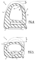
- seals 1 as illustrated in Figures 1 and 2 represent the prior art as mentioned in the preamble.
- These seals 1 especially intended to seal on a vehicle door to motor, comprise at least one flexible or semi-rigid fixing part 3, and an elastically deformable part 5 which can be of tubular shape.
- the fixing part 3 of the seals can include an adhesive 7 to fix the seal on its support.
- the seal 1 of FIG. 1 has its fixing part 3 which supports clips or pins 8 added in openings 9 of the part fixing 3.
- the seal 1 of FIG. 2 has the external face of its fixing part 3 to which a double-sided adhesive 7 is attached.
- the seal 10 has a tubular part elastically deformable 5 with a shape such that any local thermoforming operation of the joint, in particular in an area of its receiving support having at least one angle with a small radius curvature.
- a support having a angle with small radius of curvature, an angle that forms an angle generally less than or equal to 80 ° and on a radius of curvature less than or equal to 80mm knowing that this definition in no way constitutes a limitation of the present invention.
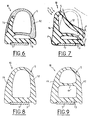
- a seal 10 according to the invention is illustrated in FIG. 3, its part elastically deformable tubular 5 having in particular a shape triangular or trapezoidal in cross section with two pillars 12 and 14 which rise from the fixing part 3 of the seal 10. These two pillars 12 and 14 are slightly inclined towards each other and are joined to each other by part arched in a semicircle.
- the arch effect is particularly interesting because pillars 12 and 14 will tend to approach one of the other in the case of a deformation of the elastically deformable part 5, whereas in the joints according to the prior art the two pillars go on the contrary move away from each other.
- the elastic part deformable 5 comprises a base 11 which extends parallel to the part of fixing 3 of the seal 10 while being connected to the latter at one end to avoid any permanent stress on adhesive 7 and improve closing energies Door.
- the two pillars 12 and 14 with an average thickness of the order of 2.5 mm, do not extend parallel to each other, but form an angle ⁇ which is generally between 10 ° and 30 °, advantageously of the order of 20 °, and the upper internal 16 and external 18 parts of the vault are generally situated between two circles C 1 and C 2 , the centers O 1 and O 2 of which are distant one from the other with a distance greater than 0.7 mm.
- the angle ⁇ which is formed between the two pillars 12 and 14 of the elastically deformable part 5 of the joint 10 is defined overall by two straight lines D 1 and D 2 passing at 2/5 and 4/5 of the height total H o of the seal 10 from its fixing part 3.
- the seal 10 can be fixed by any means suitable on its receiving support, in particular by means of a strip adhesive 7 attached to its fixing part 3, knowing that the pillar 14 of its elastically deformable part 5 is located on the door frame side, while the pillar 12 will be deformed by the body area of the door.
- the door-to-door gasket can hide the end of a panel door trim.
- the end of this trim panel P can be received, the side of the pillar 12 of the joint 10, between the base 11 of the resilient part deformable 5 of the joint and the fixing part 3.
- the resilient part deformable joint is thus enhanced by the trim panel P, this which has the effect of obtaining a regular loss of height h of the joint 10 in a angle with a small radius of curvature of the door, and to obtain a deformation in cross section of the seal 10 which will be all the better in keeping with that of the the free state.
- the sheet metal T which constitutes the support for the seal 10 can form a shoulder on the side of the pillar 14 and which will serve as lateral support for the elastically deformable part 5 of the seal 10 to prevent it from tipping over bad side.
- the fixing part 3 of the joint or sole may also have supports 19 and 20 (FIG. 3) in excess thickness, substantially on either side of the adhesive 7 to limit the loss of height h of the joint in a corner of the support. with a small radius of curvature.
- these means 22 can be formed by at least one weakening of material 24 forming a hinge which is formed in the internal wall 16 of the resilient part deformable 5 of the joint 10 for example, in particular at the level of its arch (figure 4).
- the pillars 12 and 14 of the joint 10 can be asymmetrical with, for example, a pillar 14 of greater thickness to improve the acoustics and the maintenance of the joint 10 in the areas of the receiving support having a small radius of curvature, and a pillar 12 of lesser thickness to reduce the compressibility forces of the joint.
- the pillar 14 can be at least partially made with a material elastically deformable flexible, semi-rigid or rigid.
- pillars 12 and 14 at the lower part 11 formed by the resilient part deformable 5 of the seal 10 may have a greater thickness in a way to make a joint holding beam 10.
- the arch-shaped part that brings the two together pillars 12 and 14 of the elastically deformable part 5 of the seal 10 and which forms the sealing zone of this joint has a width in cross section which is less than that of the seals according to the prior art. This results in a more great flexibility in positioning the seal on its receiving support, which is particularly interesting during the assembly of the joint by a robot which is suitable for allowing trajectory modifications.
- Figure 7 there is shown the seal 10 of Figure 6 mounted on a door and in the deformed state by the body zone Z of the closed door, the thickened pillar 14 to improve the arrest of acoustic waves shown schematically by the arrows F, the pillar 14 being for example in abutment a shoulder of the sheet metal T of the door.
- FIGS. 8 and 9 two other seals 10 according to the invention are shown.
- the two pillars 12 and 14 of the elastically deformable part 5 are directly connected to the base of fixing 3 of the joint 10, while that of FIG. 7 takes up that of FIG. 9 but in the case of an elastically deformable part 5 consisting of a bi-tube with an intermediate wall 11 '.
- one end of the seal 10 can integrate one or more wires 25 into its fixing part 3 (FIG. 3), thus that one or more strips, facilitating the extrusion of the joint but especially its removal by a dynamic robotic system of the seal. Indeed, these sons limit the elongation of the joint when it is deposited on its support.
- FIG 10 there is shown in perspective a seal seal 10 mounted on a receiving support such as a door P in an area of the support having an angle with a small radius of curvature.
- a seal according to the invention can be mounted in particular on any door, trunk or hood of a motor vehicle of a manual, semi-automatic or automatic, knowing that vehicle can be either a car, a utility, a truck, a bus, a train, a plane ...
Landscapes
- Engineering & Computer Science (AREA)
- Mechanical Engineering (AREA)
- Seal Device For Vehicle (AREA)
- Gasket Seals (AREA)
- Automobile Manufacture Line, Endless Track Vehicle, Trailer (AREA)
Abstract
Description
- une réduction du temps de cycle de dépose du joint ;
- une suppression d'une intervention humaine pour charger un joint à chaque cycle ;
- une réduction considérable du nombre des emballages, puisqu'une seule bobine peut remplacer des dizaines de cartons contenant des joints bouclés ;
- une réduction des déchets et de la pollution ;
- une réduction du nombre des références, car aujourd'hui les joints sont spécifiques à chaque type de porte ; et
- une suppression de l'opération de soudage d'une languette de préhension placée sur l'adhésif pour chaque joint, lorsque ce dernier est de type adhésivé.
- les figures 1 et 2 sont deux vues en coupe de deux joints d'étanchéité selon l'art antérieur évoqué en préambule ;
- la figure 3 est une vue en coupe d'un joint d'étanchéité selon l'invention ;
- la figure 4 est une vue en coupe du joint d'étanchéité de la figure 3 à l'état déformé ;
- la figure 5 est une vue en coupe d'un joint d'étanchéité selon l'art antérieur à l'état déformé ;
- la figure 6 est une vue en coupe d'un autre mode de réalisation d'un joint d'étanchéité selon l'invention ;
- la figure 7 est une vue en coupe du joint d'étanchéité de la figure 6 dans un angle à faible rayon de courbure ;
- les figures 8 et 9 sont des vues en coupe de deux autres modes de réalisation d'un joint d'étanchéité selon l'invention ; et
- la figure 10 est une vue en perspective partielle d'un joint selon l'invention monté dans une zone de son support de réception présentant un angle à faible rayon de courbure.
Claims (13)
- Joint d'étanchéité destiné à être monté sur un support de réception, en particulier sur une porte de véhicule automobile, présentant au moins un angle à faible rayon de courbure, ce joint comprenant au moins une partie de fixation (3) souple ou semi-rigide fixé par un adhésif (7) sur son support et une partie tubulaire élastiquement déformable (5) destinée à assurer l'étanchéité, caractérisé en ce que, après montage du joint sur son support, la partie élastiquement déformable (5) est telle qu'elle subit dans ledit angle du support une déformation en section droite qui s'inscrit globalement dans celle du joint à l'état libre.
- Joint d'étanchéité selon la revendication 1, dans lequel on donne à la partie élastiquement déformable (5) du joint, à partir de sa partie de fixation (3), une forme sensiblement triangulaire avec deux piliers latéraux (12, 14) réunis l'un à l'autre par une voûte et qui forment entre eux ùn angle (α) de l'ordre de 10° à 30°, ledit angle (α) étant défini à partir de deux droites (D1, D2) passant sensiblement par le milieu des piliers (12, 14) au 2/5 et au 4/5 de la hauteur totale du joint à partir de sa partie de fixation (3).
- Joint d'étanchéité selon la revendication 2, dans lequel on forme un angle (α) de l'ordre de 20° entre les deux piliers (12, 14) de la partie élastiquement déformable (5) du joint.
- Joint d'étanchéité selon la revendication 2 ou 3, dans lequel les parties supérieures interne (16) et externe (18) de la voûte de la partie élastiquement déformable (5) sont globalement situées entre deux cercles (C1, C2) dont les centres (O1, O2) sont distants l'un de l'autre d'une distance supérieure à 0,7mm.
- Joint d'étanchéité selon l'une quelconque des revendications précédentes, dans lequel on obtient une perte de hauteur (h) du joint dans un angle à faible rayon de courbure du support, qui est au plus égale à 2,5 mm pour un angle ayant un rayon de courbure inférieur ou égal à 80mm et sur un angle inférieur ou égal à 80°.
- Joint d'étanchéité selon l'une quelconque des revendications précédentes, dans lequel la forme de voûte qui relie les deux piliers (12, 14) de la partie élastiquement déformable (5) du joint est telle que cette zone qui assure l'étanchéité a, en section droite, une largeur réduite qui favorise le positionnement du joint par un robot sur son support de réception.
- Joint d'étanchéité selon l'une quelconque des revendications précédentes, dans lequel la partie de fixation (3) comprend des appuis (19, 20) situés sensiblement de part et d'autre de l'adhésif (7) pour limiter la déformation du joint dans un angle de son support de réception ayant un faible rayon de courbure.
- Joint d'étanchéité selon l'une quelconque des revendications précédentes, dans lequel la partie de fixation (3) du joint présente au moins un fil ou une armature d'aide au montage pour limiter son allongement lors de sa dépose.
- Joint d'étanchéité selon l'une quelconque des revendications précédentes, dans lequel sont prévus des moyens (22) pour affaiblir les efforts de compressibilité du joint.
- Joint d'étanchéité selon la revendication 9, dans lequel lesdits moyens (22) sont constitués par au moins un affaiblissement de matière (24) formant charnière qui est ménagé dans la partie élastiquement déformable (5) du joint.
- Joint d'étanchéité selon l'une quelconque des revendications précédentes, dans lequel le joint est apte à venir en appui latéral contre son support (T) pour favoriser un maintien de sa partie élastiquement déformable (5).
- Joint d'étanchéité selon l'une quelconque des revendications précédentes, dans lequel le joint est directement monté sur son support sans subir une quelconque opération de traitement spécifique dans un angle à faible rayon de courbure du support.
- Joint d'étanchéité selon l'une quelconque des revendications précédentes, dans lequel le joint est stocké et approvisionné sur une chaíne de montage en bobine, en plateau ou en container de grande longueur.
Applications Claiming Priority (2)
| Application Number | Priority Date | Filing Date | Title |
|---|---|---|---|
| FR0304544 | 2003-04-11 | ||
| FR0304544A FR2853595B1 (fr) | 2003-04-11 | 2003-04-11 | Joint d'etancheite destine a etre monte sur une porte de vehicule a moteur presentant au moins un angle a faible rayon de courbure. |
Publications (2)
| Publication Number | Publication Date |
|---|---|
| EP1466770A1 true EP1466770A1 (fr) | 2004-10-13 |
| EP1466770B1 EP1466770B1 (fr) | 2006-07-26 |
Family
ID=32865414
Family Applications (1)
| Application Number | Title | Priority Date | Filing Date |
|---|---|---|---|
| EP04290933A Expired - Lifetime EP1466770B1 (fr) | 2003-04-11 | 2004-04-08 | Joint d'étanchéité pour une porte de véhicule destiné à être monté sur un support présentant au moins un angle à faible rayon de courbure |
Country Status (5)
| Country | Link |
|---|---|
| US (1) | US7340862B2 (fr) |
| EP (1) | EP1466770B1 (fr) |
| JP (1) | JP2004314951A (fr) |
| DE (1) | DE602004001618T2 (fr) |
| FR (1) | FR2853595B1 (fr) |
Cited By (7)
| Publication number | Priority date | Publication date | Assignee | Title |
|---|---|---|---|---|
| DE202005004005U1 (de) * | 2005-03-12 | 2006-04-27 | Meteor Gummiwerke K.H. Bädje GmbH & Co. KG | Dichtungsanordnung |
| DE102004053610A1 (de) * | 2004-11-02 | 2006-05-04 | Brose Fahrzeugteile Gmbh & Co | Türbaugruppe für eine Kraftfahrzeugtür |
| DE102006052354A1 (de) * | 2006-11-07 | 2008-05-15 | GM Global Technology Operations, Inc., Detroit | Dichteinrichtung zur Abdichtung einer Tür gegenüber einem Karosserieteil und Kraftfahrzeug mit einer gegen ein Karosserieteil schwenkbaren Tür |
| FR2930808A1 (fr) * | 2008-04-30 | 2009-11-06 | Peugeot Citroen Automobiles Sa | Joint souple destine a etre fixe sur une tole au moyen d'elements de fixation par encliquetage |
| FR3014765A1 (fr) * | 2013-12-17 | 2015-06-19 | Peugeot Citroen Automobiles Sa | Joint en elastomere pour realiser l'etancheite d'un ouvrant de vehicule automobile |
| WO2019129616A1 (fr) * | 2017-12-26 | 2019-07-04 | Arcelik Anonim Sirketi | Joint d'étanchéité |
| EP3569431B1 (fr) * | 2017-01-11 | 2023-09-13 | Nippon Sheet Glass Company, Limited | Module de vitre |
Families Citing this family (16)
| Publication number | Priority date | Publication date | Assignee | Title |
|---|---|---|---|---|
| US20070245634A1 (en) * | 2006-03-23 | 2007-10-25 | Toyoda Gosei Co., Ltd. | Weather strip |
| US7488900B1 (en) * | 2006-09-22 | 2009-02-10 | Laird Technologies, Inc. | Gaskets for providing environmental sealing and/or electromagnetic interference (EMI) shielding |
| GB2459467B (en) * | 2008-04-23 | 2013-01-30 | Land Rover Uk Ltd | A motor vehicle door seal |
| KR200466484Y1 (ko) * | 2008-08-04 | 2013-04-17 | 홍성표 | 광접속함체용 메인 개스킷 |
| DE102009023455A1 (de) * | 2009-06-02 | 2010-12-09 | Volkswagen Ag | Dichtungsanordnung bei einer Klappe eines Kraftfahrzeugs |
| JP5229694B2 (ja) * | 2009-09-29 | 2013-07-03 | 豊田合成株式会社 | ウエザストリップ |
| DE102010011101A1 (de) | 2010-03-11 | 2010-10-21 | Daimler Ag | Vorrichtung zum Transport eines Anbauteils |
| US9227499B2 (en) | 2011-09-15 | 2016-01-05 | Henniges Automotive Sealing Systems North America Inc. | Weatherstrip assembly having a removable retaining member |
| DE102012106340B4 (de) * | 2012-07-13 | 2022-07-14 | Bayerische Motoren Werke Aktiengesellschaft | Dichtungsstrang zur Verklebung mit einer Fahrzeugkarosserie |
| US9089044B1 (en) | 2014-04-04 | 2015-07-21 | Laird Technologies, Inc. | EMI shielding connector gasket |
| JP6390967B2 (ja) * | 2015-03-19 | 2018-09-19 | 豊田合成株式会社 | オープニングトリムウエザストリップ |
| JP2016190523A (ja) * | 2015-03-31 | 2016-11-10 | アイシン精機株式会社 | サンルーフ装置のウエザストリップ |
| JP6595837B2 (ja) * | 2015-07-30 | 2019-10-23 | 西川ゴム工業株式会社 | ドアウェザーストリップ |
| DE102017123419A1 (de) * | 2017-10-09 | 2019-04-11 | Cqlt Saargummi Technologies S.À.R.L. | Dichtungsstrang, insbesondere zur Verarbeitung als Endlosstrang |
| CN210111193U (zh) * | 2019-08-12 | 2020-02-21 | 莫列斯有限公司 | 插头连接器 |
| CN113371176B (zh) * | 2021-07-20 | 2024-08-13 | 中国商用飞机有限责任公司 | 用于飞行器增压区舱门的密封件和配备有该密封件的飞行器增压区舱门 |
Citations (3)
| Publication number | Priority date | Publication date | Assignee | Title |
|---|---|---|---|---|
| US4374880A (en) * | 1979-11-13 | 1983-02-22 | Etablissements Mesnel | Sealing strip |
| US4708898A (en) * | 1985-03-21 | 1987-11-24 | Draftex Industries Limited | Sealing strips |
| WO2002076778A1 (fr) * | 2001-03-27 | 2002-10-03 | Saargummi Gmbh | Procede et dispositif d'application de profiles supports pour joints en caoutchouc sur des carrosseries automobiles, et profile support y relatif |
Family Cites Families (13)
| Publication number | Priority date | Publication date | Assignee | Title |
|---|---|---|---|---|
| US2379193A (en) * | 1941-06-03 | 1945-06-26 | Westinghouse Electric Corp | Refrigeration apparatus |
| DE3333474C2 (de) * | 1982-10-02 | 1996-05-02 | Draftex Ind Ltd | Kanalförmiger Dicht- oder Abschlußstreifen |
| US4620354A (en) * | 1985-05-28 | 1986-11-04 | General Motors Corporation | Method of applying weatherstrip to a vehicle body opening |
| JPS6416912U (fr) * | 1987-07-15 | 1989-01-27 | ||
| US4991352A (en) * | 1988-11-25 | 1991-02-12 | Jmk International, Inc. | Door gasket with triangular shape |
| US6647666B2 (en) * | 1998-02-13 | 2003-11-18 | Toyoda Gosei Co., Ltd. | Sealing structure of opening section in vehicle |
| JPH11227471A (ja) * | 1998-02-13 | 1999-08-24 | Toyoda Gosei Co Ltd | フロントドアウエザストリップ及びその製造方法 |
| US6405489B1 (en) * | 1999-10-13 | 2002-06-18 | Toyoda Gosei Co., Ltd. | Structure for mounting door weather strip |
| GB2360058B (en) * | 2000-01-27 | 2004-03-31 | Toyoda Gosei Kk | Door weather strip |
| US6647667B2 (en) * | 2000-03-31 | 2003-11-18 | Toyoda Gosei Co., Ltd. | Trim and seal member |
| JP3420562B2 (ja) * | 2000-09-22 | 2003-06-23 | 東洋ゴム工業株式会社 | ウェザーストリップの製造方法 |
| DE60235940D1 (de) * | 2001-07-13 | 2010-05-27 | Toyoda Gosei Kk | Dichtungsprofil und Verfahren zur dessen Herstellung |
| JP3932909B2 (ja) * | 2002-01-24 | 2007-06-20 | 豊田合成株式会社 | ウエザーストリップ |
-
2003
- 2003-04-11 FR FR0304544A patent/FR2853595B1/fr not_active Expired - Fee Related
-
2004
- 2004-04-08 EP EP04290933A patent/EP1466770B1/fr not_active Expired - Lifetime
- 2004-04-08 DE DE602004001618T patent/DE602004001618T2/de not_active Expired - Lifetime
- 2004-04-08 US US10/820,042 patent/US7340862B2/en not_active Expired - Fee Related
- 2004-04-09 JP JP2004115570A patent/JP2004314951A/ja not_active Withdrawn
Patent Citations (3)
| Publication number | Priority date | Publication date | Assignee | Title |
|---|---|---|---|---|
| US4374880A (en) * | 1979-11-13 | 1983-02-22 | Etablissements Mesnel | Sealing strip |
| US4708898A (en) * | 1985-03-21 | 1987-11-24 | Draftex Industries Limited | Sealing strips |
| WO2002076778A1 (fr) * | 2001-03-27 | 2002-10-03 | Saargummi Gmbh | Procede et dispositif d'application de profiles supports pour joints en caoutchouc sur des carrosseries automobiles, et profile support y relatif |
Cited By (8)
| Publication number | Priority date | Publication date | Assignee | Title |
|---|---|---|---|---|
| DE102004053610A1 (de) * | 2004-11-02 | 2006-05-04 | Brose Fahrzeugteile Gmbh & Co | Türbaugruppe für eine Kraftfahrzeugtür |
| DE202005004005U1 (de) * | 2005-03-12 | 2006-04-27 | Meteor Gummiwerke K.H. Bädje GmbH & Co. KG | Dichtungsanordnung |
| DE102006052354A1 (de) * | 2006-11-07 | 2008-05-15 | GM Global Technology Operations, Inc., Detroit | Dichteinrichtung zur Abdichtung einer Tür gegenüber einem Karosserieteil und Kraftfahrzeug mit einer gegen ein Karosserieteil schwenkbaren Tür |
| FR2930808A1 (fr) * | 2008-04-30 | 2009-11-06 | Peugeot Citroen Automobiles Sa | Joint souple destine a etre fixe sur une tole au moyen d'elements de fixation par encliquetage |
| FR3014765A1 (fr) * | 2013-12-17 | 2015-06-19 | Peugeot Citroen Automobiles Sa | Joint en elastomere pour realiser l'etancheite d'un ouvrant de vehicule automobile |
| WO2015092190A1 (fr) * | 2013-12-17 | 2015-06-25 | Peugeot Citroen Automobiles Sa | Joint en élastomère pour réaliser l'étanchéité d'un ouvrant de véhicule automobile |
| EP3569431B1 (fr) * | 2017-01-11 | 2023-09-13 | Nippon Sheet Glass Company, Limited | Module de vitre |
| WO2019129616A1 (fr) * | 2017-12-26 | 2019-07-04 | Arcelik Anonim Sirketi | Joint d'étanchéité |
Also Published As
| Publication number | Publication date |
|---|---|
| EP1466770B1 (fr) | 2006-07-26 |
| DE602004001618T2 (de) | 2007-08-23 |
| US7340862B2 (en) | 2008-03-11 |
| US20040261322A1 (en) | 2004-12-30 |
| FR2853595B1 (fr) | 2005-06-24 |
| DE602004001618D1 (de) | 2006-09-07 |
| FR2853595A1 (fr) | 2004-10-15 |
| JP2004314951A (ja) | 2004-11-11 |
Similar Documents
| Publication | Publication Date | Title |
|---|---|---|
| EP1466770B1 (fr) | Joint d'étanchéité pour une porte de véhicule destiné à être monté sur un support présentant au moins un angle à faible rayon de courbure | |
| EP1466769A1 (fr) | Joint d'étanchéité destiné à être monté sur le pourtour d'une porte de véhicule à moteur présentant au moins un angle à faible rayon de courbure | |
| EP0354082B1 (fr) | Coulisse de guidage de glace mobile, notamment de glace ou vitre d'automobile | |
| FR2636027A1 (fr) | Profile d'etancheite deformable sur commande pour vehicule automobile | |
| EP1518734B1 (fr) | Joint périmétrique tubulaire à monter sur le rebord d'encadrement d'une ouverture, notamment de carrosserie automobile | |
| FR2769570A1 (fr) | Toit de vehicule | |
| FR2962073A1 (fr) | Joint d'etancheite de porte | |
| EP0544961B2 (fr) | Joint d'étanchéité pour encadrement d'une carrosserie d'automobile et procédé de fabrication de ce joint | |
| FR2569455A1 (fr) | Joint d'etancheite profile permettant d'assembler deux elements de carter a bords paralleles | |
| EP1123827B1 (fr) | Joint d'étanchéité à effet insonorisant pour ouvrant de véhicule automobile, à aptitude à la déformation améliorée | |
| EP0873897B1 (fr) | Profilé tubulaire à effet insonorisant amélioré et joint comportant un tel profilé, pour encadrement d'ouvrant d'un véhicule automobile | |
| EP1426239B1 (fr) | Feuille d'étanchéité et d'insonorisation pour un élément de carrosserie, tel qu'une porte de véhicule automobile | |
| EP0296901B1 (fr) | Joint d' étanchéité entre un bâti support et un panneau mobile | |
| FR2515768A1 (fr) | Bandes d'etancheite destinees notamment a etre montees autour des ouvertures de portes ou de fenetres de vehicules a moteur | |
| EP0606801B1 (fr) | Profilé en une matière polymère, apte à se fixer par clipsage sur des plots d'une carrosserie d'automobile | |
| EP1410948B1 (fr) | Joint d'étanchéité pour bloc optique automobile | |
| EP0842823B1 (fr) | Nouveau profilé en un matériau polymère, destiné à être fixé par clipsage sur des têtes de plots rigides | |
| EP2148037A2 (fr) | Profilé d'étanchéité en particulier pour vitrage de fenêtre de bâtiment, et fenêtre l'incorporant | |
| EP0638463A1 (fr) | Dispositif d'étanchéité du type comprenant un élément de fixation sur un support du bâti ou de la caisse d'un véhicule automobile et un élément d'étanchéité | |
| EP1911621A1 (fr) | Joint d'etancheite sur porte pour vehicule | |
| WO2005030514A2 (fr) | Ensemble de toit ouvrant pour vehicule automobile et procede de fabrication d’un tel ensemble | |
| EP1710386A1 (fr) | Système d'encastrement du bord d'un panneau ou analogue dans un montant | |
| EP2113468B1 (fr) | Gaine flexible de protection pour un pare-brise | |
| FR3021258A3 (fr) | Plot de suspension pour element de suspension d'une ligne d'echappement de vehicule automobile | |
| EP1654130A1 (fr) | Essieu souple pour vehicule automobile |
Legal Events
| Date | Code | Title | Description |
|---|---|---|---|
| PUAI | Public reference made under article 153(3) epc to a published international application that has entered the european phase |
Free format text: ORIGINAL CODE: 0009012 |
|
| AK | Designated contracting states |
Kind code of ref document: A1 Designated state(s): AT BE BG CH CY CZ DE DK EE ES FI FR GB GR HU IE IT LI LU MC NL PL PT RO SE SI SK TR |
|
| AX | Request for extension of the european patent |
Extension state: AL HR LT LV MK |
|
| 17P | Request for examination filed |
Effective date: 20050127 |
|
| 17Q | First examination report despatched |
Effective date: 20050225 |
|
| AKX | Designation fees paid |
Designated state(s): DE FR GB |
|
| GRAP | Despatch of communication of intention to grant a patent |
Free format text: ORIGINAL CODE: EPIDOSNIGR1 |
|
| GRAS | Grant fee paid |
Free format text: ORIGINAL CODE: EPIDOSNIGR3 |
|
| GRAA | (expected) grant |
Free format text: ORIGINAL CODE: 0009210 |
|
| AK | Designated contracting states |
Kind code of ref document: B1 Designated state(s): DE FR GB |
|
| PG25 | Lapsed in a contracting state [announced via postgrant information from national office to epo] |
Ref country code: GB Free format text: LAPSE BECAUSE OF FAILURE TO SUBMIT A TRANSLATION OF THE DESCRIPTION OR TO PAY THE FEE WITHIN THE PRESCRIBED TIME-LIMIT Effective date: 20060726 |
|
| REG | Reference to a national code |
Ref country code: GB Ref legal event code: FG4D Free format text: NOT ENGLISH |
|
| REF | Corresponds to: |
Ref document number: 602004001618 Country of ref document: DE Date of ref document: 20060907 Kind code of ref document: P |
|
| GBV | Gb: ep patent (uk) treated as always having been void in accordance with gb section 77(7)/1977 [no translation filed] |
Effective date: 20060726 |
|
| PLBE | No opposition filed within time limit |
Free format text: ORIGINAL CODE: 0009261 |
|
| STAA | Information on the status of an ep patent application or granted ep patent |
Free format text: STATUS: NO OPPOSITION FILED WITHIN TIME LIMIT |
|
| 26N | No opposition filed |
Effective date: 20070427 |
|
| REG | Reference to a national code |
Ref country code: FR Ref legal event code: PLFP Year of fee payment: 12 |
|
| REG | Reference to a national code |
Ref country code: FR Ref legal event code: PLFP Year of fee payment: 13 |
|
| REG | Reference to a national code |
Ref country code: FR Ref legal event code: PLFP Year of fee payment: 14 |
|
| REG | Reference to a national code |
Ref country code: FR Ref legal event code: PLFP Year of fee payment: 15 |
|
| PGFP | Annual fee paid to national office [announced via postgrant information from national office to epo] |
Ref country code: FR Payment date: 20180322 Year of fee payment: 15 |
|
| PGFP | Annual fee paid to national office [announced via postgrant information from national office to epo] |
Ref country code: DE Payment date: 20180420 Year of fee payment: 15 |
|
| REG | Reference to a national code |
Ref country code: DE Ref legal event code: R119 Ref document number: 602004001618 Country of ref document: DE |
|
| PG25 | Lapsed in a contracting state [announced via postgrant information from national office to epo] |
Ref country code: DE Free format text: LAPSE BECAUSE OF NON-PAYMENT OF DUE FEES Effective date: 20191101 |
|
| PG25 | Lapsed in a contracting state [announced via postgrant information from national office to epo] |
Ref country code: FR Free format text: LAPSE BECAUSE OF NON-PAYMENT OF DUE FEES Effective date: 20190430 |