EP1466657B1 - Filterapparat mit mehr als einer Filtrationskammer - Google Patents
Filterapparat mit mehr als einer Filtrationskammer Download PDFInfo
- Publication number
- EP1466657B1 EP1466657B1 EP03008465A EP03008465A EP1466657B1 EP 1466657 B1 EP1466657 B1 EP 1466657B1 EP 03008465 A EP03008465 A EP 03008465A EP 03008465 A EP03008465 A EP 03008465A EP 1466657 B1 EP1466657 B1 EP 1466657B1
- Authority
- EP
- European Patent Office
- Prior art keywords
- filtration
- fluid
- housing
- filter device
- filter
- Prior art date
- Legal status (The legal status is an assumption and is not a legal conclusion. Google has not performed a legal analysis and makes no representation as to the accuracy of the status listed.)
- Expired - Lifetime
Links
- 238000001914 filtration Methods 0.000 title claims description 126
- 239000012530 fluid Substances 0.000 claims description 134
- 239000012528 membrane Substances 0.000 claims description 78
- 239000000835 fiber Substances 0.000 claims description 28
- 238000000034 method Methods 0.000 claims description 24
- 238000004891 communication Methods 0.000 claims description 19
- 238000004382 potting Methods 0.000 claims description 17
- 238000003466 welding Methods 0.000 claims description 14
- 238000000502 dialysis Methods 0.000 claims description 13
- 238000000108 ultra-filtration Methods 0.000 claims description 12
- 150000001875 compounds Chemical class 0.000 claims description 11
- 238000002615 hemofiltration Methods 0.000 claims description 11
- 239000000463 material Substances 0.000 claims description 11
- 238000001631 haemodialysis Methods 0.000 claims description 10
- 238000004519 manufacturing process Methods 0.000 claims description 7
- 238000002604 ultrasonography Methods 0.000 claims description 4
- 239000000706 filtrate Substances 0.000 claims description 3
- 230000005465 channeling Effects 0.000 claims 1
- 238000007789 sealing Methods 0.000 claims 1
- 210000004369 blood Anatomy 0.000 description 50
- 239000008280 blood Substances 0.000 description 50
- 239000003978 infusion fluid Substances 0.000 description 24
- 238000011282 treatment Methods 0.000 description 15
- 239000000385 dialysis solution Substances 0.000 description 11
- 239000000126 substance Substances 0.000 description 10
- 230000002093 peripheral effect Effects 0.000 description 9
- 238000006467 substitution reaction Methods 0.000 description 8
- 238000010790 dilution Methods 0.000 description 7
- 239000012895 dilution Substances 0.000 description 7
- GHYOCDFICYLMRF-UTIIJYGPSA-N (2S,3R)-N-[(2S)-3-(cyclopenten-1-yl)-1-[(2R)-2-methyloxiran-2-yl]-1-oxopropan-2-yl]-3-hydroxy-3-(4-methoxyphenyl)-2-[[(2S)-2-[(2-morpholin-4-ylacetyl)amino]propanoyl]amino]propanamide Chemical compound C1(=CCCC1)C[C@@H](C(=O)[C@@]1(OC1)C)NC([C@H]([C@@H](C1=CC=C(C=C1)OC)O)NC([C@H](C)NC(CN1CCOCC1)=O)=O)=O GHYOCDFICYLMRF-UTIIJYGPSA-N 0.000 description 6
- 229940125797 compound 12 Drugs 0.000 description 6
- 239000012510 hollow fiber Substances 0.000 description 5
- 238000010276 construction Methods 0.000 description 4
- 239000007788 liquid Substances 0.000 description 4
- 230000037452 priming Effects 0.000 description 4
- 238000004873 anchoring Methods 0.000 description 3
- 230000017531 blood circulation Effects 0.000 description 3
- 238000009826 distribution Methods 0.000 description 3
- 239000004743 Polypropylene Substances 0.000 description 2
- 239000000853 adhesive Substances 0.000 description 2
- 230000001070 adhesive effect Effects 0.000 description 2
- 230000004888 barrier function Effects 0.000 description 2
- 238000012806 monitoring device Methods 0.000 description 2
- 239000012071 phase Substances 0.000 description 2
- 239000004033 plastic Substances 0.000 description 2
- 229920003023 plastic Polymers 0.000 description 2
- 239000004417 polycarbonate Substances 0.000 description 2
- 229920000515 polycarbonate Polymers 0.000 description 2
- 239000002952 polymeric resin Substances 0.000 description 2
- -1 polypropylene Polymers 0.000 description 2
- 229920001155 polypropylene Polymers 0.000 description 2
- 229920003002 synthetic resin Polymers 0.000 description 2
- 239000002699 waste material Substances 0.000 description 2
- XLYOFNOQVPJJNP-UHFFFAOYSA-N water Substances O XLYOFNOQVPJJNP-UHFFFAOYSA-N 0.000 description 2
- QTBSBXVTEAMEQO-UHFFFAOYSA-M Acetate Chemical compound CC([O-])=O QTBSBXVTEAMEQO-UHFFFAOYSA-M 0.000 description 1
- 241000894006 Bacteria Species 0.000 description 1
- BVKZGUZCCUSVTD-UHFFFAOYSA-M Bicarbonate Chemical compound OC([O-])=O BVKZGUZCCUSVTD-UHFFFAOYSA-M 0.000 description 1
- XSQUKJJJFZCRTK-UHFFFAOYSA-N Urea Chemical compound NC(N)=O XSQUKJJJFZCRTK-UHFFFAOYSA-N 0.000 description 1
- 239000000654 additive Substances 0.000 description 1
- 102000015736 beta 2-Microglobulin Human genes 0.000 description 1
- 108010081355 beta 2-Microglobulin Proteins 0.000 description 1
- 239000000872 buffer Substances 0.000 description 1
- 239000004202 carbamide Substances 0.000 description 1
- 238000004140 cleaning Methods 0.000 description 1
- 230000001143 conditioned effect Effects 0.000 description 1
- 239000000356 contaminant Substances 0.000 description 1
- 230000001419 dependent effect Effects 0.000 description 1
- 238000013461 design Methods 0.000 description 1
- 238000009792 diffusion process Methods 0.000 description 1
- 239000003792 electrolyte Substances 0.000 description 1
- 230000005670 electromagnetic radiation Effects 0.000 description 1
- 239000002158 endotoxin Substances 0.000 description 1
- 239000011796 hollow space material Substances 0.000 description 1
- 230000000977 initiatory effect Effects 0.000 description 1
- 238000005304 joining Methods 0.000 description 1
- 239000007791 liquid phase Substances 0.000 description 1
- 238000013508 migration Methods 0.000 description 1
- 230000005012 migration Effects 0.000 description 1
- 210000002381 plasma Anatomy 0.000 description 1
- 238000002616 plasmapheresis Methods 0.000 description 1
- 229920002635 polyurethane Polymers 0.000 description 1
- 239000004814 polyurethane Substances 0.000 description 1
- 239000011148 porous material Substances 0.000 description 1
- 239000000047 product Substances 0.000 description 1
Images


Classifications
-
- A61M1/0023—
-
- B—PERFORMING OPERATIONS; TRANSPORTING
- B01—PHYSICAL OR CHEMICAL PROCESSES OR APPARATUS IN GENERAL
- B01D—SEPARATION
- B01D63/00—Apparatus in general for separation processes using semi-permeable membranes
- B01D63/02—Hollow fibre modules
- B01D63/04—Hollow fibre modules comprising multiple hollow fibre assemblies
-
- B—PERFORMING OPERATIONS; TRANSPORTING
- B01—PHYSICAL OR CHEMICAL PROCESSES OR APPARATUS IN GENERAL
- B01D—SEPARATION
- B01D61/00—Processes of separation using semi-permeable membranes, e.g. dialysis, osmosis or ultrafiltration; Apparatus, accessories or auxiliary operations specially adapted therefor
- B01D61/24—Dialysis ; Membrane extraction
- B01D61/30—Accessories; Auxiliary operation
-
- B—PERFORMING OPERATIONS; TRANSPORTING
- B01—PHYSICAL OR CHEMICAL PROCESSES OR APPARATUS IN GENERAL
- B01D—SEPARATION
- B01D61/00—Processes of separation using semi-permeable membranes, e.g. dialysis, osmosis or ultrafiltration; Apparatus, accessories or auxiliary operations specially adapted therefor
- B01D61/58—Multistep processes
-
- B—PERFORMING OPERATIONS; TRANSPORTING
- B01—PHYSICAL OR CHEMICAL PROCESSES OR APPARATUS IN GENERAL
- B01D—SEPARATION
- B01D63/00—Apparatus in general for separation processes using semi-permeable membranes
- B01D63/02—Hollow fibre modules
-
- B—PERFORMING OPERATIONS; TRANSPORTING
- B01—PHYSICAL OR CHEMICAL PROCESSES OR APPARATUS IN GENERAL
- B01D—SEPARATION
- B01D65/00—Accessories or auxiliary operations, in general, for separation processes or apparatus using semi-permeable membranes
-
- B—PERFORMING OPERATIONS; TRANSPORTING
- B01—PHYSICAL OR CHEMICAL PROCESSES OR APPARATUS IN GENERAL
- B01D—SEPARATION
- B01D61/00—Processes of separation using semi-permeable membranes, e.g. dialysis, osmosis or ultrafiltration; Apparatus, accessories or auxiliary operations specially adapted therefor
- B01D61/14—Ultrafiltration; Microfiltration
- B01D61/145—Ultrafiltration
-
- B—PERFORMING OPERATIONS; TRANSPORTING
- B01—PHYSICAL OR CHEMICAL PROCESSES OR APPARATUS IN GENERAL
- B01D—SEPARATION
- B01D61/00—Processes of separation using semi-permeable membranes, e.g. dialysis, osmosis or ultrafiltration; Apparatus, accessories or auxiliary operations specially adapted therefor
- B01D61/24—Dialysis ; Membrane extraction
- B01D61/243—Dialysis
-
- Y—GENERAL TAGGING OF NEW TECHNOLOGICAL DEVELOPMENTS; GENERAL TAGGING OF CROSS-SECTIONAL TECHNOLOGIES SPANNING OVER SEVERAL SECTIONS OF THE IPC; TECHNICAL SUBJECTS COVERED BY FORMER USPC CROSS-REFERENCE ART COLLECTIONS [XRACs] AND DIGESTS
- Y10—TECHNICAL SUBJECTS COVERED BY FORMER USPC
- Y10T—TECHNICAL SUBJECTS COVERED BY FORMER US CLASSIFICATION
- Y10T29/00—Metal working
- Y10T29/49—Method of mechanical manufacture
- Y10T29/49609—Spring making
- Y10T29/49613—Spring making for human comfort
Definitions
- the present invention relates to a filter device for the filtration of fluids.
- one or more embodiments of the present invention relate to filter devices for use in dialysis-type treatments and for filtration processes similar to and related to the haemodialysis process, such as haemofiltration, haemodiafiltration and ultrafiltration, as well as to a method for making a housing of a filtration device.
- Filter devices having hollow-fibre membranes are used inter alia (i.a.) in the area of dialysis for a wide variety of purposes.
- Such filters may thus also be referred to as dialysers, these being used for example in haemodialysis, in which blood is directed into and along the inside of the semi-permeable walls of the hollow fibres while dialysis fluid is directed around the outside of the hollow fibres.
- Various convection and diffusion processes may thereby take place across the walls of the hollow fibres. These processes serve for example to purify and to remove excess fluid from the blood.
- the electrolyte concentration in the blood can be conditioned using infusion fluids, and buffers such as bicarbonate or acetate can be added to the blood.
- the haemodialysis process is effective at removing substances having a low molecular weight, but may be less effective at removing substances having a middle molecular weight.
- Low molecular weight substances in the context of dialysis typically include substances such as urea, having a molecular weight below 5kDa.
- Filter devices of this type may also be employed in so-called haemofiltration, in which a substitution fluid is added to the blood.
- a substitution fluid is added to the blood.
- the blood is directed through the inside of the hollow fibres, although in this case no dialysis fluid is passed around the outside of the fibres.
- excess fluids in particular water as well as waste products, are removed from the blood by means of a pressure difference across the membrane, here comprised by the semi-permeable walls of the hollow fibres.
- the substitution fluid can be added either prior or subsequent to the filtration in pre- or post-dilution modes.
- Haemofiltration is more effective at removing substances having a so-called middle molecular weight lying within the range between approximately 5kDa-30kDa such as Beta-2-Microglobulin.
- a further application for the present type of filter device includes haemodiafiltration: a combination of haemodialysis and haemofiltration, in which dialysate flows across one side of the membrane while blood flows across the other side and at the same time, a pressure gradient exists across the membrane.
- Infusion fluid may be added to the blood either prior to or after the filtration. This process can result in a higher filtration rate and is especially effective at removing substances having a low and middle molecular weight.
- a further process for which such filters may be used is known as plasmapheresis, in which aqueous blood-plasma is filtered out of the blood and returned to the blood after treatment.
- Such filter devices are also used in filtration processes wherein undesirable substances may be removed from blood, water or other fluids.
- the above-mentioned filter devices can equally be used as so-called ultrafilters for the production of substitution or infusion fluids.
- infusion fluid may be directed into the filter on one side of a semi-permeable membrane, and is filtered across the membrane by means of a pressure difference.
- the infusion fluid can be sterile-filtered by removal of endotoxins, bacteria and other contaminants.
- Ultrafilters generally have a similar construction to dialyser-type filters although they are generally smaller in dimension and are not generally used as dialysers in the dialysis process. Ultrafilters are usually employed during a blood filtration treatment in addition to a dialysis filter, the filtrate from the ultrafilter creating the infusion fluid which is then fed into the blood either on the blood side of the dialysis filter device or into blood in the blood tubes.
- These filter devices are usually so constructed that the hollow-fibres are arranged as a loose bundle lying longitudinally within a tubular housing.
- the housing is provided at each end with an end-cap, and the hollow-fibre bundle is arranged between the ends of the housing so that the end-caps enclose the ends of the hollow-fibre bundle.
- the ends of the fibres are usually embedded within and secured by a potting compound made from a two-component polymer resin. Except as noted below, the potting compound completely surrounds the ends of the hollow fibres and is molded to the inside of the ends of the housing to create a seal between the header chamber and the inside of the tubular housing.
- the extreme ends of the hollow fibres open out above the potting compound into a hollow space (hereafter: header-chamber) located in-between the end cap and the end of the hollow-fibre bundle. It is therefore possible, with the appropriate arrangement of inlets and outlets, to provide, in a manner known per se, various forms of filter such as the previously mentioned haemodialysis filters, haemofilters, haemodiafilters, ultrafilters etc.
- a first fluid may be directed into and through the inside of the semi-permeable hollow fibres.
- This first fluid may exit from the fibre column having had certain substances removed and possibly certain substances added.
- a second fluid may be present on the outside of the hollow fibres.
- This second fluid can either flow through the housing, past and around the hollow fibres, via appropriately located inlet and outlet means; or it can be removed from the first fluid and directed out of the housing via a suitable outlet, for example by means of a pressure differential across the hollow-fibre membrane.
- This second fluid may be a purified form of the first fluid, a dialysis fluid for the exchange of substances into and out of the first fluid across the hollow-fibre membranes, or a waste fluid removed from the first fluid, inter alia.
- one of the aforementioned filters is applied in the area of dialysis, for example in haemodialysis, various fluid lines (conduits) are connected to it. These fluid lines on the one hand lead blood from the patient to the blood side of the filter and then back to the patient. Additional fluid lines lead the dialysis fluid from a dialysis fluid supply, controlled by a dialysis machine also sometimes referred to as a dialysis monitoring device, to the dialysate side of the filter and after passage through the filter further to a drain.
- the blood side here refers to the area of the filter through which the blood of the patient is led, while the dialysate side refers to the area of the filter or the filter housing through which the dialysis fluid is lead.
- the blood side and the dialysate side are separated from each other in the filter housing by one or more semi-permeable membranes and these sides correspond respectively to the sides along which the previously mentioned first and second fluids pass.
- a haemofiltration process may be combined in series with a haemodialysis or haemodiafiltration process, thereby necessitating more than one filter device.
- a filter cartridge comprising more than one filtration compartment is disclosed for example in WO 02/47785 .
- two hollow-fibre bundles are arranged in adjacent compartments which are separated by a wall in which a communicating aperture is provided for the flow of filtrate or dialysate through both compartments.
- a further dialyser device is known from DE-A-196 07 162 , in which a filtration device for substitution fluid is disclosed along with a haemodiafiltration device integrated within a single housing.
- Filter membrane means in the form of hollow fibres are provided within both compartments.
- One end of the hollow fibres of the filter for a substitution fluid is sealed off by means of potting compound or by a cover.
- a problem encountered with this device is that it is difficult to completely expel all of the air contained within the compartment for the substitution fluid at the start of a filtration process, both the air around the outside of the hollow fibres and in the inside of the fibres.
- Air on the inside of the fibres is pushed by liquid passing across the membranes into a header chamber at either the blood entry or exit of the dialysis compartment thereby causing unnecessary contact between blood and air in the blood flow circuit. This may be avoided by passing substitution fluid through the filtration compartment prior to passing blood through the haemodiafiltration compartment although this involves additional work for an operator.
- substitution fluid through the filtration compartment prior to passing blood through the haemodiafiltration compartment although this involves additional work for an operator.
- air around the outside of the membranes is not completely expelled during the initiation phase of filtration and may be fed through into the blood during a treatment. This increases the thrombogeneicity of the blood filtration process.
- a further drawback of this disclosure exists in that filtration of the substitution fluid takes place from the outside through to the inside of the hollow-fibre membranes.
- EP-A-0264695 discloses a method and an arrangement for cleaning blood in a filtration system, the filtration system comprising multiple compartments and a symmetrically split housing.
- EP-A-0890368 discloses an apparatus for the treatment of blood by dialysis including a membrane exchange device.
- the membrane exchange devise comprises multiple compartments and a symmetrically split housing.
- WO 00/44478 discloses hollow fiber modules for the filtration and dialysis of blood.
- the hollow fibers are disposed as a bundle parallel to one another in a tubular filter housing composed of two half shells. The two half shells are connected by a hinge.
- FR-A-2231421 discloses a hollow fiber filtration module having an asymmetrically split housing with separate internal bundles of hollow fibers.
- a filter device in which at least two fluid filtration compartments are provided within a filter housing, the respective compartments being separated by a continuous internal wall. In this way, more than one fluid may be filtered at any one time by filter means in respective separate chambers of a single filter device.
- a first surface of the filter membrane means is in communication with both an inlet and an outlet.
- filter membrane means in each compartment each have a first and a second surface, wherein the first or second surface are each in fluid communication with respective external flow ports.
- the external fluid flow port may be connected to a fluid supply or drain means, which fluid supply or drain means are located externally of the filter housing.
- an external fluid flow port may be connected to an inflow port in fluid flow communication with a separate filtration compartment to thereby lead away fluid emerging from a second surface of filter membrane means to be infused in a fluid involved in a separate filtration treatment in another filtration compartment.
- an infusion fluid having passed across a filtration membrane may be channelled to an inflow or outflow section of an adjacent filtration compartment in which blood is filtered.
- a first surface of the filter membrane means in each compartment is in communication with an inlet and an outlet of a fluid filtration compartment thereby ensuring that air may be effectively expelled from each compartment during an initial phase of operation of each filter.
- the filter device of the invention may be operated in such a manner that fluids to be passed across a membrane means in any compartment may be passed from a first surface to a second surface of the membrane means.
- the membrane means are hollow fibre membranes
- ultrafiltration usually takes place by passing fluid at a higher pressure through the inside surfaces of the fibre membranes. The fluid then passes through to the outside surface and is filtered in the process.
- fluid may also be passed from second, exterior surfaces through to the first, inside surfaces of hollow fibre type membranes.
- Filtration may be carried out from the outside surface to the inside surface using a conventional type of fibre or alternatively, using a special fibre, the walls of which are adapted for filtration in the said direction.
- Such fibres may be made from a more rigid material than conventional fibres.
- the filter membrane may be comprised of a bundle of hollow-fibres, preferably semi-permeable membrane fibres, in which case the first surface designates collectively the insides of the hollow fibres in the bundle and the second surface designates the outside surfaces of the hollow fibres.
- hollow-fibres are employed as filter membrane means
- the outside surfaces of the hollow-fibres are in communication with the external fluid flow port in the above example.
- the aforementioned continuous internal wall (or walls) within the filter device of the invention divide the interior of the filter housing into separate filtration compartments, such that there is no fluid communication across the wall (or walls) between the respective filtration compartments.
- the filter device of the invention may be configured such that the respective first surface (or first surfaces) of the filter membrane means in one compartment are in fluid flow communication with the respective first surface (or first surfaces) of filter membrane means in at least one other compartment.
- This enables a fluid to be passed through more than one filtration process in series.
- the second surface (or surfaces) of a filter membrane means in a filtration compartment may be in fluid flow communication with a first surface (or surfaces) of a filter membrane in another compartment.
- the fluid having been purified by passing across the filter membrane of one compartment may be added to the fluid being or having been filtered in another compartment. This may be achieved, for example by means of an external flow port from one filtration compartment being connected for channelling fluid to an inlet or outlet for fluid entering or leaving a first surface of a filter membrane in another compartment.
- the housing means of the filter device of the invention have elongate longitudinally extending walls which are of tubular geometry.
- the longitudinal walls include at least one external wall continuous or discontinuous about the circumference, and one or more internal walls extending between opposite ends of the housing.
- the one or more internal walls divide the interior of the external housing into two or more internal compartments.
- more than one blood filtration process may be carried out in addition to an ultrafiltration.
- the outlet portion of the hollow-fibres in one filtration compartment may be in fluid communication with the inlet portion of a bundle of hollow fibres in another compartment of the filter device.
- a replacement infusion fluid ultrafiltered in one compartment of the filter device may then be added to the blood at any stage in the blood filtration process before, after or in one or more of the other compartments of the filter device; e.g. before passage of the blood through the membranes (pre-dilution), between successive treatments (mid-dilution) or after one or two (or more) treatments (post-dilution).
- a first fluid such as an infusion fluid may be treated in a first compartment while a second fluid (usually blood; the first fluid being an infusion solution described above) may be subjected to more than one filtration process in series.
- a haemofiltration treatment may be carried out in a second compartment, the fluid thereby removed from the second fluid escaping from the filter through an external fluid flow port.
- the second fluid emerging at a fluid outlet of the membranes of the said second compartment may then be directed into the filtration membranes of a third filtration chamber.
- semi-permeable hollow fibres are used as a filter membrane means, these may be held in place at their ends by a so-called potting compound.
- the potting compound may consist of a hardened polymer resin, such as two-component polyurethane, molded to the internal walls of the tubular housing and serves as a barrier enclosing the second surface of the membranes within a compartment of the tubular housing. It also maintains the apertures of the hollow fibres such that the (internal) first surfaces of the fibres are open at an outlet or inlet end of the housing.
- the ends of the housing are advantageously enclosed by end-caps, thereby providing so-called header chambers.
- Each end-cap may be constructed so as to enclose more than one header chamber, with each header chamber being provided with at least one fluid inflow or outflow port, and possibly with one or more additional fluid flow ports, for example for supplying additives to the fluid within the header chamber.
- each end-cap may enclose each header chamber in correspondence with each of the filtration compartments internal of the overall filter housing.
- the header chambers of a single end-cap may be separated from one another by wall means and by a seal member placed between the header chamber wall and an internal wall and/or the surface of the potting compound in order to prevent migration of fluid from one header chamber to another.
- the hollow fibre bundle of more than one filtration compartment may open out into a single header chamber.
- header chambers may be connected for fluid flow by connecting together fluid flow ports of respective header chambers using molded or tubing line conduit means.
- the housing comprises continuous internal walls which divide the filter into separate filtration compartments. No single compartment would thereby be delimited entirely by peripheral or external walls of the housing, each compartment being delimited at least partly by an internal wall.
- the housing may for example be tubular, and in one embodiment may be made up of two separate longitudinally extending sections of a housing wall. The respective portions of the housing may be joined together along seam-type joints by any suitable means such as by bonding or welding e.g. using ultrasound or laser welding. In the case of laser-welding techniques, the two sections of the filter housing would benefit from particular light reflective properties in order to ensure an adequate weld.
- one of the housing sections may be made from substantially clear, uncoloured material, while the other may contain a light-reflective dye suitable for causing plastics material at the boundary of the two housing portions to melt sufficiently to form a bond.
- one housing portion may be made from polycarbonate while another section may be made from polypropylene.
- Assembly of the filter device may be achieved by combining the steps of filling the respective filtration compartments as initially defined by the separate sections with hollow-fibres and then assembling the housing.
- hollow-fibres may be placed within the respective filtration compartments defined by each respective single section of the housing.
- the housing sections may then be brought together and fixed in position enclosing the respective fibre bundles in their compartments.
- the housing which is here, by way of example, shown tubular sections may thereby each include corresponding portions of internal walls, whereby the respective edges of the various corresponding wall portions would then desirably be bonded to one another as would the outer walls of the said sections. Bonding may be carried out by any suitable method such as by using adhesive means or by welding as described more fully herein.
- the internal wall may not be in portions but instead may be provided integral with a first one of the tubular housing sections, with the second section comprising only an outer wall portion of the housing joined on its internal face to the respective internal and outer wall portions of the aforementioned first section.
- the first section is larger than the second section.
- the first section may make up more than half of the outer circumference or periphery of the resulting housing, while the second portion may make up less than one half of the outer periphery, perhaps as little as one third or one quarter.
- one side of the cross-sectional rectangle may be comprised of the said second portion or cover portion, while the main first portion of the housing could comprise substantially three sides of the said cross-sectional rectangle.
- internal walls could advantageously be provided integral with the said first portion, or with both portions.
- At least one outer wall of a respective filtration compartment may be provided parallel to an internal wall of a same compartment. This feature may enable a more optimal filling of the fibre bundle within each compartment.
- An end of the housing portion may be provided with one or more apertures or recesses for engaging the potting compound which restrains the ends of the hollow fibre bundles.
- Such an embodiment may be useful when the end-caps are provided with fluid flow ports for more than one fluid intended to be channelled towards different surfaces of the hollow fibres.
- the fluid intended to flow around the outside of the hollow fibres may flow though a peripheral flow port of an end-cap and around a channel formed and bounded by a sill portion of the tubular housing and then through a filtration compartment of the tubular housing.
- the present invention also encompasses a method of making a filter housing of the invention in which the housing is made from two longitudinally extending portions which are bonded together along seam-type joins.
- a preferred method of bonding is by welding, in particular by laser or ultrasound welding.
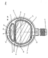
- the filter device shown in Figures 1 , 2 and 3 comprises a housing 1 and two end-caps 13 and 14, one arranged at each end of the housing.
- the housing 1 is comprised of a longitudinally extending generally tubular wall having two opposed ends. Respective compartments 2 and 3 are separated by a continuous wall means 8.
- Filter membrane means (not shown) are arranged longitudinally within respective filtration compartments 2 and 3 ( Fig. 2 and 3 ). These usually each comprise a bundle of semi-permeable hollow fibres secured at their ends by a potting compound 12 ( Fig. 3 ) which extends around an end portion of the wall of the housing 1.
- the open ends of the hollow fibres, embedded in the potting compound 12 constitute inlet or outlet apertures 4a, 4b and 5a, 5b for fluid entering or leaving a filtration compartment along a first surface of the filter membrane means therein.
- the open apertures 4a, 4b and 5a, 5b of the ends of the hollow fibres open out into a respective header chamber 17, 18 arranged within the end caps 13, 14.
- Fluid inflow and outflow ports 6, 7, 15, 15a, 16 and 16a for respective first and second fluids are arranged on the end-cap 13 and 14.
- Ports 15 and 16 and 15a and 16a are in fluid flow communication with header chambers 17, 18 and 17a, 18a inside each end-cap 13, 14 and with a first surface of the filter membranes of each filtration compartment 2, 3.
- External fluid flow ports 6, 7 and 11 are illustrated provided in fluid flow communication with a respective second side of the filter membranes of the respective filtration compartments 2, 3 arranged within the housing 1.
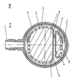
- the fluid flow ports 6, 7, 11 could optionally be provided on portions of the wall of the housing 1 nearby but not necessarily integral with an end-cap as shown in Figs. 2 and 2a .
- a conduit means 19 may be provided for conducting a fluid emerging from the second surface of the filter membrane of a filtration compartment 3 via an external fluid flow port 7 and an optional additional fluid inflow port 22 (see Figs 1 and 3 ) into the header chamber 17 which is in fluid flow connection with another fluid passing along a first surface of filter membrane means of the separate filtration compartment 2.
- the ultrafiltrate emerging from an ultrafilter arranged in filtration compartment 3 within the housing 1 may be used to dilute another fluid such as blood, being filtered, by haemofiltration or haemodialysis or haemodiafiltration in additional, discrete filtration compartment 2.
- the infusion fluid is generated in a filtration compartment at a higher pressure than the pressure of the first fluid such as blood in the inflow or outflow area of the filtration compartment into which the infusion fluid is subsequently directed.
- a check or non-return valve (not shown) may be present in the conduit means 19 in order to prevent accidental passage of blood from a blood filtration compartment into an ultrafiltration compartment.
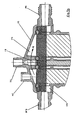
- the potting compound 12 can be anchored to the housing 1 at a peripheral region and can enclose a lip or flange portion 23 formed at the end of the housing 1.
- the potting compound 12 may additionally be anchored to the housing at apertures 20, 20a in the housing.
- the apertures 20, 20a are provided in two rows in the example illustrated at Fig. 3 , and serve to allow the flow of fluid between the enclosed peripheral channels 24, 24a and respective internal filtration compartments 2 or 3 to the second surface (or the exterior surface) of the hollow fibres.
- the apertures 20, 20a comprise two sets of holes communicating with two separate channels 24, 24a (see Fig. 3 ). One set of holes 20 communicates with chamber 2 while the other set 20a communicates with chamber 3.
- apertures 20, 20a may additionally serve as anchoring means for the potting compound 12 which may flow through some of the apertures while in a liquid phase prior to hardening.
- a sill or flange 27 may be provided integral with the housing 1 such that when an end-cap 13, 14 is disposed in place upon the housing 1, the channels 24, 24a are present in the space created by the header cap peripheral wall and the housing 1.
- Inlet ports 6 and 7 can therefore be provided in a lateral or peripheral portion of the end-cap 13 for inflow or outflow of fluids to or from the outside of the hollow fibres.
- infusion fluid to be purified may be fed into the filtration compartment 3 through inflow port 25.
- the fluid then passes into a lower header chamber 18a of the end-cap 14 which communicates with filtration compartment 3, after which it passes along the inside surface (first surface) of the hollow fibre membranes of the fibre bundle inside the filtration compartment 3.
- the outlet flow port 16 is held open for air to escape from the filtration compartment 3 before it becomes filled with infusion fluid.
- the outlet port 16 may then be closed when infusion fluid has filled the filter membranes, after which the infusion fluid is forced by a pressure gradient across the membranes through to the second, exterior surface of the membranes, from where it leaves the filtration compartment 3 through external flow port 7.
- the two header chambers 17, 18 are clearly visible in Fig. 3 , separated from one another by wall portion 28 of the end-cap 13 and by an additional seal 21.
- a conduit 19 is partly shown, this being provided connected to flow port 22 and also to the outlet port 7 for the first fluid e.g. ultrafiltrate, emerging from the first filtration compartment 3.
- This corresponds to either a pre- or post-dilution set-up, in which infusion fluid entering the header chamber 17 via fluid flow port 22 is infused into a second fluid prior to or after passing through the hollow fibre bundle contained within the filtration compartment 2.
- the second fluid could be made to flow in either direction (up or down) in this example.
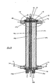
- FIG. 4 A possible construction of the filter device, in particular, the housing of the filter device can be appreciated from Figures 4 and 5 .
- Two sections 41 and 42 of the housing 1 are shown joined at seams 35 of peripheral wall portions 51, 50 as well as at internal wall portions 48, 49 which together make up continuous internal wall 8 and which furthermore define internal surfaces 52 and 53.
- end-cap 14 may comprise a fluid inflow port 11 which may be molded integrally therewith and which may allow fluid such as for example dialysis fluid to flow to or from the outside surface or surfaces of membrane means within compartment 2.
- fibre bundles may be laid within the compartments 2 and 3 prior to closing the compartments by joining section 42 to section 41.
- the wall surfaces 50, 51, 52 and 53 are arranged to be substantially parallel.
- the internal wall portions 48, 49 may advantageously be provided hollow along one or more portions of their length, in order to reduce material usage and for uniformity of wall thicknesses throughout the housing portions.
- the enclosed channels 24, 24a are shown allowing fluid to flow to or from port 11 and into or out of a filtration chamber 2 via apertures 20, 20a. Similar channels 24, 24a (not shown in Fig. 4 or 5 ) are provided in the upper end cap 13.
- the apertures 20 in filtration compartment 2 are kept separate from the channel 24a and apertures 20a of filtration compartment 3 by means of either a seal (not shown) or by additionally including barrier means (not shown) between the internal wall portions 48, 49 and the outer regions of the wall of end cap 14.
- Fig. 6 the end portion of a housing according to an embodiment of the invention is illustrated.
- a sill 27 around an outside portion of the wall of the housing 1 is shown, around which an end cap may be sealingly fitted.
- An upper portion of the housing wall is provided with apertures 20 which serve two purposes. On the one hand, these apertures serve to provide an anchoring means for the potting compound 12 which secures the hollow fibres.
- some of the apertures serve as inlets into the filtration compartment on the outside surface of hollow fibres contained therein. The fluid may thereby be distributed into the compartment inflowing from the external port.
- Seal means 21 are shown in position corresponding to the positions of the respective housing outer walls and the inner walls separating the respective filtration compartments 2 and 3.
- Figs 2a and 5a there is shown a possible embodiment of the filter device in which only the filtration compartment 2 intended for dialysate fluid flow in a blood filtration process is provided with liquid distribution apertures 20 at the ends of the compartment. Dialysis liquid may thereby flow first through fluid flow port 6 and to the outside of the filter membranes inside filtration chamber 2 via the peripheral channel 24 and the distribution apertures 20.
- the ultrafiltration compartment 3 is provided with an external flow port 7a on the wall of the housing 1.
- the arrangement shown in Figs 2a and 5a avoids the potential need for an additional seal or wall component possibly requiring welding between the internal walls separating the respective chambers 17 and 18 and the inside of the end-cap 13 of the previously described embodiment.
- a filter device having three internal filtration compartments within a unitary housing 101 is illustrated.
- a first filter e.g. an ultrafiltration filter is provided in a compartment 103 located adjacent and in between two outer dialysis-type filtration compartments 102, 104.
- Fluid flow ports 106 and 107 allow fluid such as dialysis fluid to enter or leave filtration compartments communicating with a second surface of filter membranes provided therein. In the example shown, these are provided at a peripheral portion of an end-cap 113, although they could also be provided on the wall of the housing 101 (see the example of Figs. 2a and 5a ).
- Distribution apertures 120 may be used to ensure anchoring of the potting compound (not shown) and allow inflow and outflow of fluids via an enclosed channel 124 as in the two-compartment model described previously.
- fluid inflow and outflow means to the second surface of the filter membranes of the ultrafiltration compartment 103 may be provided molded integrally with the wall of the housing 101.
- a conduit 119 may provide for infusion fluid emerging from compartment 103 via port 109 to flow into a header chamber within end-cap 113 via inlet port 122, where it is added to another fluid, e.g. blood filtered via the first surfaces of filtration membranes in either or both of compartments 102 and 104.
- a three compartment device is shown in respective longitudinal section and in cross section.
- the internal compartments of the device are defined by two wall portions 148 and 149 joined at seam portions 35. These define between them a central compartment 103, and two outer compartments 102 and 104. Some internal walls of the device are in parallel configuration in order to optimize the filling of the internal spaces with hollow fibre membranes.
- header chamber 117 within the upper end-cap 113 may be configured such that the respective first surfaces of filter membrane means within compartments 102 and 104 can be disposed in fluid flow communication.
- the infusion fluid in the arrangement may be added to the blood via exit flow port 109 ( Figs. 7 and 8 ), through conduit 119 ( Figs. 7 and 8 ) and an additional inflow port 122 ( Fig. 7 ) in the header chamber 117 in an arrangement corresponding to a mid-dilution step.
- Flow port 115 is optional and may serve for fluid inflow or outflow or may serve to bleed air from the compartment 104 while it is being filled with e.g. blood or otherwise being primed, before being sealed again prior to the commencement of filtration.
- the wall members 130 and 131 may keep separate the dialysate flowing around channel 124 into or out of chambers 102 and 104.
- the wall means could be replaced by an equivalent seal means (not shown).
- an infusion fluid may be passed into the flow port 125 ( Fig. 9 ) as indicated by arrow B.
- air may be let out through flow port 116.
- the flow port 116 may be sealed and purified infusion fluid (or other priming fluid which may be used) flows across the membrane means of the filtration compartment 103 emerging from a second surface of the membrane means through a fluid outlet 109 as shown in Fig. 7 .
- the fluid may be channelled into the header chamber 117 via conduit 119 already described.
- a second fluid usually blood
- Air may be bled from the chamber at port 115 (e.g. during priming or during use), before the blood flows across the header chamber 117 along the direction of arrow A and onto the first side of filter membrane means in compartment 102 before exiting along the direction of arrow D at flow port 126.
- a conduit could be connected to fluid flow ports of whichever header chambers it may be desired to connect.
- Dialysis fluid may be passed into the compartments 104 and 102 via flow ports 107 and 111 respectively and may exit the compartments through ports 106 and 110.
- fluid may be removed without addition of dialysis fluid, in which case corresponding inflow ports may be kept sealed.
- the device shown in Fig. 9 may be operated in a number of combinations of filtration processes described previously in this specification.
- FIGs. 11, 11a, 12 , 13 and 13a various possibilities are shown for connecting together shell portions 41, 42, 141, 142 of housing 1, 101.
- Figs 11, 11a and 12 show a possibility in which a two-compartment housing 1 is formed from hinged housing shell sections 41, 42.
- Continuous wall means 8 consists of wall portions 48 and 49.
- the wall means 8 could be made from a single wall portion either integral with one shell portion 41 or 42 or it could be fixed to the shell portions 41, 42 using a bonding technique.
- Numeral 160 denotes fluid flow ports in general which may be inflow or outflow ports.
- FIGs 11, 11a, 12 , 13 and 13a the flow ports 160 are shown schematically integral with walls of housing 1, 101, although these could equally well be provided at end-caps of the filter device.
- the hinged housing 1 could be employed for a three-compartment type device or for a device with more than three compartments. Bonding of the housing 1 is achieved by welding or by adhesive means along seam 35, 135 (see also Fig. 4 ).
- Figs. 13 and 13a show a similar housing 101 in two parts which are shell portions 141 and 142. These are bonded or welded along laterally and longitudinally arranged seams 135.
- Figs 13 and 13a The device of Figs 13 and 13a is shown with three compartments 102, 103 and 104, although the same technique could be employed for a device having only two compartments or for a device having more than three compartments.
- the continuous wall portions 8 could be provided either from wall portions 148 and 149 or from a single portion attached to only one shell segment or added as a separate element.
- the respective portions may be held in an opened position as shown in Figure 12 for filling with filter means such as hollow fibre bundles in each respective compartment of shell portion 41 or 141 before completing the housing 1, 101 by closing shell portion 42, 142 on top of said portion 41 in which filter means are laid longitudinally.
- the internal wall portions 48, 49, 148, 148 may be welded together or bonded to thereby create internal walls 8 and to generate an integral filter housing.
- One method of welding includes laser welding as mentioned or welding using other electromagnetic means. The welding may be carried out while filter means such as membranes in the form of hollow fibers are in place within respective chambers in the housing.
- Materials used for the housing may advantageously include materials having particular light reflective properties in order to ensure an adequate weld.
- one of the housing sections may be made from substantially clear, uncoloured material, while the other may contain a light-reflective dye suitable for causing plastics material at the boundary of the two housing portions to melt sufficiently to form a bond.
- one housing portion may be made from polycarbonate while another section may be made from polypropylene.
- the different refractive indices of the materials may produce sufficient heat for a weld to form when laser or electromagnetic radiation is aimed at the join or seam 35, 135.
Claims (24)
- Filtervorrichtung umfassend ein Gehäuse (1, 101), wobei das Gehäuse (1, 101) einen runden Querschnitt aufweist und mindestens zwei Fluidfiltrationsabteile (2, 3, 102, 103, 104) einschließt, wobei jedes Filtrationsabteil (2, 3, 102, 103, 104) jeweilige Filtermembranmittel mit einer entsprechenden ersten und zweiten Fläche umfasst, wobei die erste Fläche von jedem Filtermembranmittel in Fluidverbindung mit einem Eingang von jedem Filtrationsabteil (2, 3, 102, 103, 104) ist, wobei die zweite Fläche in Fluidverbindung mit mindestens einem äußeren Fluidflussanschluss (6, 7, 7a, 11, 106, 107, 109, 110, 111) von jedem Filtrationsabteil (2, 3, 102, 103, 104) ist, wobei jeweilige angrenzende Filtrationsabteile (2, 3, 102, 103, 104) mittels durchgehender Innenwandmittel (8) so voneinander getrennt sind, dass mehr als ein Fluid gleichzeitig durch die Filtervorrichtung gefiltert werden kann, und wobei das Gehäuse aus zwei sich längserstreckenden Schalenabschnitten (41, 42, 141, 142) besteht, die entlang einer oder mehreren äußeren und einer oder mehreren inneren Längsverbindungen (35) miteinander verbunden sind, dadurch gekennzeichnet, dass ein der sich längserstreckenden Schalenabschnitte weniger als die Hälfte des Wandkreisumfangs des Gehäuses umschreibt.
- Filtervorrichtung nach Anspruch 1, umfassend zwei Filtrationsabteile (2, 3), die innerhalb des Gehäuses (1) angeordnet sind, und wobei eines der Filtrationsabteile (3) dazu geeignet ist, Ultrafiltration eines ersten Fluids durchzuführen, während das andere Abteil (2) dazu geeignet ist, gleichzeitig entweder Hämofiltration oder Hämodialyse oder Hämodiafiltration eines zweiten Fluids durchzuführen.
- Filtervorrichtung nach Anspruch 1, wobei die Vorrichtung ein Gehäuse (1, 101) umfasst, innerhalb welchem mindestens drei Filtrationsabteile (102, 103, 104) angeordnet sind, und wobei mindestens ein der Filtrationsabteile (103) dazu geeignet ist, Ultrafiltration eines ersten Fluids durchzuführen, während jedes der anderen Abteile (102, 104) dazu geeignet ist, gleichzeitig entweder Hämofiltration oder Hämodialyse oder Hämodiafiltration eines zweiten Fluids durchzuführen.
- Filtervorrichtung nach Anspruch 3, wobei die ersten Flächen von mindestens zwei der Filtermembranmittel in getrennten Filtrationsabteilen (2, 102, 104) in Fluidflussverbindung sind.
- Filtervorrichtung nach einem der vorhergehenden Ansprüche, wobei die zweiten Flächen von den Filtermembranmitteln eines der Filtrationsabteile (3, 103) in Fluidverbindung mit der ersten Fläche von den Filtermembranmitteln in einem anderen der Filtrationsabteile (2, 102, 104) sind.
- Filtervorrichtung nach einem der vorhergehenden Ansprüche, wobei die erste Fläche von den Filtermembranmitteln eines der Filtrationsabteile (3, 103) mit den zweiten Flächen von den Filtermembranmitteln in einem anderen der Filtrationsabteile (2, 102, 104) via dem äußeren Fluidflussanschluss (7, 7a, 109) in Fluidverbindung ist.
- Filtervorrichtung nach einem der vorhergehenden Ansprüche, wobei die Filtermembranmittel ein Bündel von semipermeablen Hohlfasermembranen umfassen, und wobei die erste Fläche die Innenflächen der Hohlfasern im Bündel umfasst, und wobei die zweite Fläche die Außenflächen der Hohlfasern im Bündel umfasst.
- Filtervorrichtung nach Anspruch 7, wobei das Gehäuse (1) zwei gegenüberliegende Enden und eine dazwischen liegende röhrenförmige Außenwand umfasst, wobei die Hohlfasermembranen innerhalb jedes der Filtrationsabteile (2, 3, 102, 103, 104) entlang der Längsrichtung des Gehäuses (1) angeordnet sind, wobei die Enden der Hohlfasermembranen mittels eines Tränkmittels (12) gesichert sind und in diesem eingebettet sind.
- Filtervorrichtung nach Anspruch 8, wobei eine Endkappe (13, 14, 13, 114) an jedem Ende des Gehäuses (1) befestigt ist, und wobei eine Kopfkammer (17, 18, 117, 118) zwischen jeder der Endkappen (13, 14, 13, 114) und den Enden der Hohlfasern vorgesehen ist.
- Filtervorrichtung nach Anspruch 8 oder 9, wobei die Außenwand des Gehäuses (1) an ihren Enden Eingriffsabschnitte (20) zum positiven Eingriff in die Tränkmittel (12) aufweist.
- Filtervorrichtung nach Anspruch 10, wobei die Eingriffsabschnitte eine oder mehrere Öffnungen (20) an jedem Ende der Außenwand beinhalten.
- Filtervorrichtung nach einem der Ansprüche 9-11, wobei jede der Kopfkammern (17, 18, 117, 118) in getrennte Kammern bezüglich jedes Filtrationsabteils (2, 3, 102, 103, 104) aufgeteilt ist, wobei jede getrennte Kopfkammer (17, 18, 117, 118) mit einen Fluidflussanschluss (15, 16, 25, 26, 115, 116, 125, 126, 128) versehen ist.
- Filtervorrichtung nach Anspruch 12, wobei entsprechende Kopfkammern (17, 18, 117, 118) innerhalb einer einzelnen Endkappe (13, 14, 113, 114) mittels eines Wandabschnitts (28) und eines Dichtungselements (21) voneinander getrennt sind.
- Filtervorrichtung nach Anspruch 12 oder 13, wobei entsprechende getrennte Kopfkammern (17, 18, 117, 118) in Fluidflussverbindung sind, so dass ein erstes Fluid, das aus einem ersten Filtrationsabteil (3, 103) hervorgeht, aus einer Kopfkammer in eine andere Kopfkammer geleitet werden kann, aus welcher das erste Fluid in die Filtermembranmittel eines zweiten Filtrationsabteils (2, 102, 104) fließt.
- Filtervorrichtung nach einem der vorhergehenden Ansprüche, wobei Leitungsmittel (19, 119) vorgesehen sind, um Fluid, das als Filtrat aus den zweiten Flächen von einem der Filtermembranmittel in einem ersten Abteil (3, 103) durch einen äußeren Fluidflussanschluss (7, 7a, 109) hervorgeht, in einen Fluidflussanschluss (22, 122) einzuleiten, welcher in Fluidverbindung mit einem anderen Fluid ist, das durch die zweiten Flächen von Filtermembranmitteln in einem anderen der Filtrationsabteile (2, 102, 104) fließt.
- Filtervorrichtung nach Anspruch 1, wobei die zwei sich längserstreckenden Schalenabschnitte (41, 42) miteinander verschweißt sind.
- Filtervorrichtung nach Anspruch 16, wobei die zwei sich längserstreckenden Schalenabschnitte (41, 42) lasergeschweißt sind.
- Filtervorrichtung nach Anspruch 16, wobei die zwei sich längserstreckenden Schalenabschnitte (41, 42) ultraschallgeschweißt sind.
- Filtervorrichtung nach einem der Ansprüche 1-18, wobei mindestens zwei nach innen gerichtete Wände (50, 51, 52, 53) von entsprechenden Filtrationsabteilen (2, 3, 102, 103, 104) parallel zueinander sind.
- Filtervorrichtung nach einem der Ansprüche 1-19, wobei entsprechende sich längserstreckende Schalenabschnitte (41, 42) des Gehäuses (1) aus voneinander unterschiedlichen Materialien hergestellt sind, die aus der Gruppe umfassend polymere Materialien gewählt sind.
- Filtervorrichtung nach einem der Ansprüche 1-20, wobei die erste Fläche von jedem Filtermembranmittel in Fluidverbindung mit einem Eingang und einem Ausgang (4a, 5a, 4b, 5b) von jedem Filtrationsabteil (2, 3, 102, 103, 104) ist.
- Filtervorrichtung nach einem der vorhergehenden Ansprüche, umfassend mindestens drei diskrete Filtrationsabteile (2, 3, 102, 103, 104), wobei zwei der Abteile (2, 3, 102, 103, 104) dazu geeignet sind, serielle Dialyse oder Hämodiafiltration oder Hämofiltration oder jede Kombination der genannten Prozesse durchzuführen.
- Verfahren zur Herstellung einer Filtervorrichtung nach einem der Ansprüche 1-22, wobei das Gehäuse (1) aus zwei sich längserstreckenden Schalenabschnitten (41, 141, 42, 142) besteht, die Außenwände des Gehäuses (1, 101) und Innenwände (50, 51, 52, 52), die entsprechende Filtrationsabteile (2, 3, 102, 103, 104) innerhalb des Gehäuses (1, 101) voneinander trennen, darstellen, wobei das Verfahren das Zusammenfügen der Schalenabschnitte entlang innerer und äußerer Nähte (35, 135) umfasst.
- Verfahren nach Anspruch 23, wobei das Verbinden der Schalenabschnitte (41, 42, 141, 142) durch Laserschweißen oder Ultraschallschweißen durchgeführt wird.
Priority Applications (5)
| Application Number | Priority Date | Filing Date | Title |
|---|---|---|---|
| EP03008465A EP1466657B1 (de) | 2003-04-11 | 2003-04-11 | Filterapparat mit mehr als einer Filtrationskammer |
| US10/708,774 US7790029B2 (en) | 2003-04-11 | 2004-03-24 | Filter device having more than one filtration compartment |
| KR20040024808A KR101131676B1 (ko) | 2003-04-11 | 2004-04-12 | 한 개 이상의 여과격실이 있는 여과장치 |
| JP2004116541A JP4659383B2 (ja) | 2003-04-11 | 2004-04-12 | 2つ以上のろ過区画を有するフィルタ装置 |
| US11/736,310 US7622041B2 (en) | 2003-04-11 | 2007-04-17 | Method for making a filter device having more than one filtration compartment |
Applications Claiming Priority (1)
| Application Number | Priority Date | Filing Date | Title |
|---|---|---|---|
| EP03008465A EP1466657B1 (de) | 2003-04-11 | 2003-04-11 | Filterapparat mit mehr als einer Filtrationskammer |
Publications (2)
| Publication Number | Publication Date |
|---|---|
| EP1466657A1 EP1466657A1 (de) | 2004-10-13 |
| EP1466657B1 true EP1466657B1 (de) | 2012-10-03 |
Family
ID=32865008
Family Applications (1)
| Application Number | Title | Priority Date | Filing Date |
|---|---|---|---|
| EP03008465A Expired - Lifetime EP1466657B1 (de) | 2003-04-11 | 2003-04-11 | Filterapparat mit mehr als einer Filtrationskammer |
Country Status (4)
| Country | Link |
|---|---|
| US (2) | US7790029B2 (de) |
| EP (1) | EP1466657B1 (de) |
| JP (1) | JP4659383B2 (de) |
| KR (1) | KR101131676B1 (de) |
Cited By (1)
| Publication number | Priority date | Publication date | Assignee | Title |
|---|---|---|---|---|
| WO2023017073A1 (de) | 2021-08-13 | 2023-02-16 | B. Braun Avitum Ag | Mehrteiliger dialysator |
Families Citing this family (28)
| Publication number | Priority date | Publication date | Assignee | Title |
|---|---|---|---|---|
| US20070095741A1 (en) * | 2003-10-31 | 2007-05-03 | Berends Hendrik Johan F | Filter module |
| WO2005044428A1 (en) * | 2003-11-07 | 2005-05-19 | Gambro Lundia Ab | End-cap assembly with pump hose for a filter and filter comprising such an end-cap assembly |
| DE602004017689D1 (de) | 2003-11-21 | 2008-12-24 | Samsung Electronics Co Ltd | Vorrichtung und Methode zur Erzeugung von kodierten Blockanordnungen für ein Alpha-Kanalbild sowie Alpha-Kanalkodierungs und -dekodierungsvorrichtung und -methode. |
| WO2007009496A1 (en) * | 2005-07-22 | 2007-01-25 | Mahiout Arezki Ph D | Differential hemodialysis or hemodiafiltration |
| EP2313125B1 (de) * | 2008-07-15 | 2016-04-06 | Mirimedical Llc | Doppelfaserbündeldialysator |
| CN102164647B (zh) | 2008-09-24 | 2014-04-16 | 杰里·谢瓦利茨 | 用于交替式流体过滤的筛网过滤器模块 |
| US8753515B2 (en) | 2009-12-05 | 2014-06-17 | Home Dialysis Plus, Ltd. | Dialysis system with ultrafiltration control |
| US8501009B2 (en) | 2010-06-07 | 2013-08-06 | State Of Oregon Acting By And Through The State Board Of Higher Education On Behalf Of Oregon State University | Fluid purification system |
| US9446354B2 (en) | 2010-08-25 | 2016-09-20 | Repligen Corporation | Device, system and process for modification or concentration of cell-depleted fluid |
| WO2012036235A1 (ja) | 2010-09-16 | 2012-03-22 | 三菱レイヨン株式会社 | 中空糸膜シート状物の製造方法、中空糸膜モジュールの製造方法及び中空糸膜シート状物の製造装置 |
| DE102011107980B4 (de) * | 2011-07-18 | 2017-11-02 | Fresenius Medical Care Deutschland Gmbh | Filtermodul, Verfahren zur Herstellung eines Hohlfasermembranbündels, Disposable und Blutbehandlungsvorrichtung |
| ES2640953T3 (es) | 2011-10-07 | 2017-11-07 | Outset Medical, Inc. | Purificación de líquido de intercambio de calor para un sistema de diálisis |
| CN105597545B (zh) * | 2012-04-02 | 2020-03-20 | 三菱化学株式会社 | 中空纤维膜组件的制造方法和具有中空纤维膜组件的中空纤维膜单元 |
| DE102013012674A1 (de) * | 2013-07-31 | 2015-02-05 | Mann + Hummel Gmbh | Filtermodul mit Hohlfasern |
| DE102014201248A1 (de) | 2014-01-23 | 2015-07-23 | Volkswagen Ag | Feuchtetauscher und Brennstoffzellenanordnung mit einem solchen |
| EP3131663A2 (de) | 2014-03-29 | 2017-02-22 | Princeton Trade and Technology Inc. | Blutverarbeitungskartuschen und systeme sowie verfahren für extrakorporale bluttherapien |
| ES2864727T3 (es) | 2014-04-29 | 2021-10-14 | Outset Medical Inc | Sistema y métodos de diálisis |
| US10426884B2 (en) | 2015-06-26 | 2019-10-01 | Novaflux Inc. | Cartridges and systems for outside-in flow in membrane-based therapies |
| US10399040B2 (en) | 2015-09-24 | 2019-09-03 | Novaflux Inc. | Cartridges and systems for membrane-based therapies |
| EP3374636B1 (de) | 2015-11-10 | 2020-06-03 | Repligen Corporation | Einweg-wechselstrom-tangentialfilteranlagen |
| EP3178539A1 (de) * | 2015-12-11 | 2017-06-14 | Gambro Lundia AB | Filtervorrichtung, system und verfahren zur filterung von fluiden |
| EP3463508A1 (de) | 2016-05-27 | 2019-04-10 | The Charles Stark Draper Laboratory, Inc. | Hämotransfiltrationshohlfaservorrichtung |
| JP7025408B2 (ja) | 2016-08-19 | 2022-02-24 | アウトセット・メディカル・インコーポレイテッド | 腹膜透析システム及び方法 |
| EP3415225B1 (de) | 2017-06-14 | 2021-03-03 | Gambro Lundia AB | System und verfahren zur filtration und/oder dilatation von flüssigkeiten |
| KR102264517B1 (ko) * | 2018-06-08 | 2021-06-11 | 코오롱인더스트리 주식회사 | 중공사막 모듈 제조방법 및 이에 의해 제조된 중공사막 모듈 |
| EP3842129B1 (de) | 2019-12-24 | 2024-03-06 | Gambro Lundia AB | Sterilfilterbaugruppe |
| TW202206129A (zh) * | 2020-07-01 | 2022-02-16 | 新加坡商阿瓦克科技私人有限公司 | 透析應用之過濾裝置 |
| TWI824735B (zh) * | 2022-09-22 | 2023-12-01 | 友達光電股份有限公司 | 分光裝置及血液透析系統 |
Citations (2)
| Publication number | Priority date | Publication date | Assignee | Title |
|---|---|---|---|---|
| US4211597A (en) * | 1977-06-10 | 1980-07-08 | Cordis Dow Corp. | Method for making artificial kidney |
| US4343668A (en) * | 1980-06-04 | 1982-08-10 | Hospal Sodip Sa | Method of producing bundles of hollow fibres potted at their ends |
Family Cites Families (19)
| Publication number | Priority date | Publication date | Assignee | Title |
|---|---|---|---|---|
| FR2231421B1 (de) | 1973-05-30 | 1976-05-07 | Rhone Poulenc Ind | |
| US4226378A (en) * | 1976-02-13 | 1980-10-07 | Baxter Travenol Laboratories, Inc. | Method and apparatus for winding hollow filaments |
| US4341005A (en) * | 1980-11-06 | 1982-07-27 | Strimbeck, Davis & Soloway | Manufacture of hollow fiber fluid fractionating cells |
| IT1167767B (it) * | 1981-05-26 | 1987-05-13 | Inphardial Spa | Dializzatore per emodialisi a fibre cave con incorporato un separatore di filtrato per analisi ematochimiche |
| DE3326704A1 (de) * | 1983-07-23 | 1985-01-31 | Josef 6902 Sandhausen Magasi | Verfahren und vorrichtung zur haemodialyse |
| DE3634763A1 (de) * | 1986-10-11 | 1988-04-28 | Josef Magasi | Vorrichtung und verfahren zur blutreinigung |
| SE454847B (sv) | 1987-08-31 | 1988-06-06 | Gambro Dialysatoren | Anordning for diffusion och/eller filtrering samt forfarande for tillverkning av denna anordning |
| IT1215765B (it) * | 1988-01-22 | 1990-02-22 | Grace W R & Co | Dispositivo di emodiafiltrazione erelativo procedimento di emodiafiltrazione. |
| SE465095B (sv) | 1988-07-07 | 1991-07-22 | Gambro Dialysatoren | Taetning innefattande en ring av ett flexibelt material avsedd att pressas mellan tvaa parallella, foeretraedesvis slaeta taetningsytor |
| SE502103C2 (sv) | 1991-08-01 | 1995-08-14 | Gambro Dialysatoren | Filterenhet för överföring av massa och/eller värme innehållande hålrumsfibrer |
| SE502222C2 (sv) * | 1994-01-17 | 1995-09-18 | Althin Medical Ab | Sätt vid dialys |
| DE19607162C2 (de) | 1996-02-26 | 1998-01-15 | Fresenius Ag | Verwendung eines Dialysators mit zwei Modulen zur Durchführung eines Verfahrens zum Filtrieren und sofortigen Verwenden von Substituatflüssigkeit in einer Hämodialfiltrationsvorrichtung |
| EP0844015B1 (de) * | 1996-11-21 | 2003-10-15 | Fresenius Medical Care Deutschland GmbH | Hohlfasermembrantrennvorrichtung |
| IT1293309B1 (it) * | 1997-07-09 | 1999-02-16 | Sis Ter Spa | Apparecchiatura per il trattamento del sangue con dispositivo di scambio a membrana |
| SE515122C2 (sv) * | 1999-01-29 | 2001-06-11 | Gambro Lundia Ab | Filter och metod för tillverkning av filter för dialys |
| US6315895B1 (en) | 1999-12-30 | 2001-11-13 | Nephros, Inc. | Dual-stage hemodiafiltration cartridge |
| US6423223B1 (en) | 2000-08-31 | 2002-07-23 | Donald A. Northcut | Multi-element, reverse osmosis, liquid filter system with flushing and filtering circuits |
| DE60120761T3 (de) * | 2000-12-11 | 2010-02-18 | Nephros, Inc. | Hämodiafiltration/hämofiltrations-patronen |
| US6830685B2 (en) * | 2001-12-05 | 2004-12-14 | Fresenius Usa, Inc. | Filtering device with associated sealing design and method |
-
2003
- 2003-04-11 EP EP03008465A patent/EP1466657B1/de not_active Expired - Lifetime
-
2004
- 2004-03-24 US US10/708,774 patent/US7790029B2/en active Active
- 2004-04-12 KR KR20040024808A patent/KR101131676B1/ko active IP Right Grant
- 2004-04-12 JP JP2004116541A patent/JP4659383B2/ja not_active Expired - Lifetime
-
2007
- 2007-04-17 US US11/736,310 patent/US7622041B2/en active Active
Patent Citations (2)
| Publication number | Priority date | Publication date | Assignee | Title |
|---|---|---|---|---|
| US4211597A (en) * | 1977-06-10 | 1980-07-08 | Cordis Dow Corp. | Method for making artificial kidney |
| US4343668A (en) * | 1980-06-04 | 1982-08-10 | Hospal Sodip Sa | Method of producing bundles of hollow fibres potted at their ends |
Cited By (2)
| Publication number | Priority date | Publication date | Assignee | Title |
|---|---|---|---|---|
| WO2023017073A1 (de) | 2021-08-13 | 2023-02-16 | B. Braun Avitum Ag | Mehrteiliger dialysator |
| DE102021121108A1 (de) | 2021-08-13 | 2023-02-16 | B.Braun Avitum Ag | Mehrteiliger Dialysator |
Also Published As
| Publication number | Publication date |
|---|---|
| KR20040089559A (ko) | 2004-10-21 |
| US20070181488A1 (en) | 2007-08-09 |
| US20040200768A1 (en) | 2004-10-14 |
| KR101131676B1 (ko) | 2012-03-28 |
| US7622041B2 (en) | 2009-11-24 |
| EP1466657A1 (de) | 2004-10-13 |
| JP2004337845A (ja) | 2004-12-02 |
| US7790029B2 (en) | 2010-09-07 |
| JP4659383B2 (ja) | 2011-03-30 |
Similar Documents
| Publication | Publication Date | Title |
|---|---|---|
| US7622041B2 (en) | Method for making a filter device having more than one filtration compartment | |
| JP4213384B2 (ja) | 二段式血液透析濾過カートリッジ | |
| KR100649260B1 (ko) | 이중-스테이지 여과 카트리지 | |
| KR100604460B1 (ko) | 혈액 투석여과/혈액 여과 카트리지 | |
| US5942112A (en) | Hollow fiber ultradialyzer apparatus | |
| EP3397376B1 (de) | System und verfahren zur filtration von fluiden | |
| CN100518836C (zh) | 透析过滤的方法 | |
| EP3638406B1 (de) | System und verfahren zur filtration und/oder dilatation von flüssigkeiten | |
| BG112033A (bg) | Диализатор |
Legal Events
| Date | Code | Title | Description |
|---|---|---|---|
| PUAI | Public reference made under article 153(3) epc to a published international application that has entered the european phase |
Free format text: ORIGINAL CODE: 0009012 |
|
| AK | Designated contracting states |
Kind code of ref document: A1 Designated state(s): AT BE BG CH CY CZ DE DK EE ES FI FR GB GR HU IE IT LI LU MC NL PT RO SE SI SK TR |
|
| AX | Request for extension of the european patent |
Extension state: AL LT LV MK |
|
| 17P | Request for examination filed |
Effective date: 20050225 |
|
| AKX | Designation fees paid |
Designated state(s): AT BE BG CH CY CZ DE DK EE ES FI FR GB GR HU IE IT LI LU MC NL PT RO SE SI SK TR |
|
| 17Q | First examination report despatched |
Effective date: 20070730 |
|
| 111Z | Information provided on other rights and legal means of execution |
Free format text: AT BE BG CH CY CZ DE DK EE ES FI FR GB GR HU IE IT LU MC NL PT RO SE SI SK TR Effective date: 20090504 |
|
| GRAP | Despatch of communication of intention to grant a patent |
Free format text: ORIGINAL CODE: EPIDOSNIGR1 |
|
| RIC1 | Information provided on ipc code assigned before grant |
Ipc: A61M 1/16 20060101ALI20120402BHEP Ipc: B01D 61/58 20060101AFI20120402BHEP Ipc: B01D 61/30 20060101ALI20120402BHEP Ipc: B01D 63/04 20060101ALI20120402BHEP Ipc: B01D 65/00 20060101ALI20120402BHEP Ipc: B01D 63/02 20060101ALI20120402BHEP |
|
| D11X | Information provided on other rights and legal means of execution (deleted) | ||
| GRAS | Grant fee paid |
Free format text: ORIGINAL CODE: EPIDOSNIGR3 |
|
| GRAA | (expected) grant |
Free format text: ORIGINAL CODE: 0009210 |
|
| AK | Designated contracting states |
Kind code of ref document: B1 Designated state(s): AT BE BG CH CY CZ DE DK EE ES FI FR GB GR HU IE IT LI LU MC NL PT RO SE SI SK TR |
|
| REG | Reference to a national code |
Ref country code: GB Ref legal event code: FG4D |
|
| REG | Reference to a national code |
Ref country code: CH Ref legal event code: EP Ref country code: AT Ref legal event code: REF Ref document number: 577707 Country of ref document: AT Kind code of ref document: T Effective date: 20121015 |
|
| REG | Reference to a national code |
Ref country code: IE Ref legal event code: FG4D |
|
| REG | Reference to a national code |
Ref country code: DE Ref legal event code: R096 Ref document number: 60342237 Country of ref document: DE Effective date: 20121129 |
|
| REG | Reference to a national code |
Ref country code: AT Ref legal event code: MK05 Ref document number: 577707 Country of ref document: AT Kind code of ref document: T Effective date: 20121003 |
|
| PG25 | Lapsed in a contracting state [announced via postgrant information from national office to epo] |
Ref country code: SI Free format text: LAPSE BECAUSE OF FAILURE TO SUBMIT A TRANSLATION OF THE DESCRIPTION OR TO PAY THE FEE WITHIN THE PRESCRIBED TIME-LIMIT Effective date: 20121003 |
|
| REG | Reference to a national code |
Ref country code: NL Ref legal event code: VDEP Effective date: 20121003 |
|
| PG25 | Lapsed in a contracting state [announced via postgrant information from national office to epo] |
Ref country code: ES Free format text: LAPSE BECAUSE OF FAILURE TO SUBMIT A TRANSLATION OF THE DESCRIPTION OR TO PAY THE FEE WITHIN THE PRESCRIBED TIME-LIMIT Effective date: 20130114 Ref country code: FI Free format text: LAPSE BECAUSE OF FAILURE TO SUBMIT A TRANSLATION OF THE DESCRIPTION OR TO PAY THE FEE WITHIN THE PRESCRIBED TIME-LIMIT Effective date: 20121003 Ref country code: SE Free format text: LAPSE BECAUSE OF FAILURE TO SUBMIT A TRANSLATION OF THE DESCRIPTION OR TO PAY THE FEE WITHIN THE PRESCRIBED TIME-LIMIT Effective date: 20121003 Ref country code: NL Free format text: LAPSE BECAUSE OF FAILURE TO SUBMIT A TRANSLATION OF THE DESCRIPTION OR TO PAY THE FEE WITHIN THE PRESCRIBED TIME-LIMIT Effective date: 20121003 |
|
| PG25 | Lapsed in a contracting state [announced via postgrant information from national office to epo] |
Ref country code: GR Free format text: LAPSE BECAUSE OF FAILURE TO SUBMIT A TRANSLATION OF THE DESCRIPTION OR TO PAY THE FEE WITHIN THE PRESCRIBED TIME-LIMIT Effective date: 20130104 Ref country code: CY Free format text: LAPSE BECAUSE OF FAILURE TO SUBMIT A TRANSLATION OF THE DESCRIPTION OR TO PAY THE FEE WITHIN THE PRESCRIBED TIME-LIMIT Effective date: 20121003 Ref country code: BE Free format text: LAPSE BECAUSE OF FAILURE TO SUBMIT A TRANSLATION OF THE DESCRIPTION OR TO PAY THE FEE WITHIN THE PRESCRIBED TIME-LIMIT Effective date: 20121003 Ref country code: PT Free format text: LAPSE BECAUSE OF FAILURE TO SUBMIT A TRANSLATION OF THE DESCRIPTION OR TO PAY THE FEE WITHIN THE PRESCRIBED TIME-LIMIT Effective date: 20130204 |
|
| PG25 | Lapsed in a contracting state [announced via postgrant information from national office to epo] |
Ref country code: AT Free format text: LAPSE BECAUSE OF FAILURE TO SUBMIT A TRANSLATION OF THE DESCRIPTION OR TO PAY THE FEE WITHIN THE PRESCRIBED TIME-LIMIT Effective date: 20121003 |
|
| PG25 | Lapsed in a contracting state [announced via postgrant information from national office to epo] |
Ref country code: CZ Free format text: LAPSE BECAUSE OF FAILURE TO SUBMIT A TRANSLATION OF THE DESCRIPTION OR TO PAY THE FEE WITHIN THE PRESCRIBED TIME-LIMIT Effective date: 20121003 Ref country code: EE Free format text: LAPSE BECAUSE OF FAILURE TO SUBMIT A TRANSLATION OF THE DESCRIPTION OR TO PAY THE FEE WITHIN THE PRESCRIBED TIME-LIMIT Effective date: 20121003 Ref country code: DK Free format text: LAPSE BECAUSE OF FAILURE TO SUBMIT A TRANSLATION OF THE DESCRIPTION OR TO PAY THE FEE WITHIN THE PRESCRIBED TIME-LIMIT Effective date: 20121003 Ref country code: BG Free format text: LAPSE BECAUSE OF FAILURE TO SUBMIT A TRANSLATION OF THE DESCRIPTION OR TO PAY THE FEE WITHIN THE PRESCRIBED TIME-LIMIT Effective date: 20130103 Ref country code: SK Free format text: LAPSE BECAUSE OF FAILURE TO SUBMIT A TRANSLATION OF THE DESCRIPTION OR TO PAY THE FEE WITHIN THE PRESCRIBED TIME-LIMIT Effective date: 20121003 |
|
| PLBE | No opposition filed within time limit |
Free format text: ORIGINAL CODE: 0009261 |
|
| STAA | Information on the status of an ep patent application or granted ep patent |
Free format text: STATUS: NO OPPOSITION FILED WITHIN TIME LIMIT |
|
| PG25 | Lapsed in a contracting state [announced via postgrant information from national office to epo] |
Ref country code: RO Free format text: LAPSE BECAUSE OF FAILURE TO SUBMIT A TRANSLATION OF THE DESCRIPTION OR TO PAY THE FEE WITHIN THE PRESCRIBED TIME-LIMIT Effective date: 20121003 Ref country code: IT Free format text: LAPSE BECAUSE OF FAILURE TO SUBMIT A TRANSLATION OF THE DESCRIPTION OR TO PAY THE FEE WITHIN THE PRESCRIBED TIME-LIMIT Effective date: 20121003 |
|
| 26N | No opposition filed |
Effective date: 20130704 |
|
| REG | Reference to a national code |
Ref country code: DE Ref legal event code: R097 Ref document number: 60342237 Country of ref document: DE Effective date: 20130704 |
|
| PG25 | Lapsed in a contracting state [announced via postgrant information from national office to epo] |
Ref country code: MC Free format text: LAPSE BECAUSE OF FAILURE TO SUBMIT A TRANSLATION OF THE DESCRIPTION OR TO PAY THE FEE WITHIN THE PRESCRIBED TIME-LIMIT Effective date: 20121003 |
|
| REG | Reference to a national code |
Ref country code: CH Ref legal event code: PL |
|
| REG | Reference to a national code |
Ref country code: IE Ref legal event code: MM4A |
|
| PG25 | Lapsed in a contracting state [announced via postgrant information from national office to epo] |
Ref country code: CH Free format text: LAPSE BECAUSE OF NON-PAYMENT OF DUE FEES Effective date: 20130430 Ref country code: LI Free format text: LAPSE BECAUSE OF NON-PAYMENT OF DUE FEES Effective date: 20130430 |
|
| PG25 | Lapsed in a contracting state [announced via postgrant information from national office to epo] |
Ref country code: IE Free format text: LAPSE BECAUSE OF NON-PAYMENT OF DUE FEES Effective date: 20130411 |
|
| PGFP | Annual fee paid to national office [announced via postgrant information from national office to epo] |
Ref country code: GB Payment date: 20140325 Year of fee payment: 12 |
|
| PGFP | Annual fee paid to national office [announced via postgrant information from national office to epo] |
Ref country code: DE Payment date: 20140430 Year of fee payment: 12 Ref country code: FR Payment date: 20140328 Year of fee payment: 12 |
|
| PG25 | Lapsed in a contracting state [announced via postgrant information from national office to epo] |
Ref country code: TR Free format text: LAPSE BECAUSE OF FAILURE TO SUBMIT A TRANSLATION OF THE DESCRIPTION OR TO PAY THE FEE WITHIN THE PRESCRIBED TIME-LIMIT Effective date: 20121003 |
|
| PG25 | Lapsed in a contracting state [announced via postgrant information from national office to epo] |
Ref country code: HU Free format text: LAPSE BECAUSE OF FAILURE TO SUBMIT A TRANSLATION OF THE DESCRIPTION OR TO PAY THE FEE WITHIN THE PRESCRIBED TIME-LIMIT; INVALID AB INITIO Effective date: 20030411 Ref country code: LU Free format text: LAPSE BECAUSE OF NON-PAYMENT OF DUE FEES Effective date: 20130411 |
|
| REG | Reference to a national code |
Ref country code: DE Ref legal event code: R119 Ref document number: 60342237 Country of ref document: DE |
|
| GBPC | Gb: european patent ceased through non-payment of renewal fee |
Effective date: 20150411 |
|
| PG25 | Lapsed in a contracting state [announced via postgrant information from national office to epo] |
Ref country code: GB Free format text: LAPSE BECAUSE OF NON-PAYMENT OF DUE FEES Effective date: 20150411 Ref country code: DE Free format text: LAPSE BECAUSE OF NON-PAYMENT OF DUE FEES Effective date: 20151103 |
|
| REG | Reference to a national code |
Ref country code: FR Ref legal event code: ST Effective date: 20151231 |
|
| PG25 | Lapsed in a contracting state [announced via postgrant information from national office to epo] |
Ref country code: FR Free format text: LAPSE BECAUSE OF NON-PAYMENT OF DUE FEES Effective date: 20150430 |