EP1466535B1 - Method for assembling components of smoking articles - Google Patents
Method for assembling components of smoking articles Download PDFInfo
- Publication number
- EP1466535B1 EP1466535B1 EP03008450A EP03008450A EP1466535B1 EP 1466535 B1 EP1466535 B1 EP 1466535B1 EP 03008450 A EP03008450 A EP 03008450A EP 03008450 A EP03008450 A EP 03008450A EP 1466535 B1 EP1466535 B1 EP 1466535B1
- Authority
- EP
- European Patent Office
- Prior art keywords
- articles
- group
- drum
- cigarette
- article
- Prior art date
- Legal status (The legal status is an assumption and is not a legal conclusion. Google has not performed a legal analysis and makes no representation as to the accuracy of the status listed.)
- Expired - Lifetime
Links
Images


Classifications
-
- A—HUMAN NECESSITIES
- A24—TOBACCO; CIGARS; CIGARETTES; SIMULATED SMOKING DEVICES; SMOKERS' REQUISITES
- A24C—MACHINES FOR MAKING CIGARS OR CIGARETTES
- A24C5/00—Making cigarettes; Making tipping materials for, or attaching filters or mouthpieces to, cigars or cigarettes
- A24C5/47—Attaching filters or mouthpieces to cigars or cigarettes, e.g. inserting filters into cigarettes or their mouthpieces
- A24C5/471—Attaching filters or mouthpieces to cigars or cigarettes, e.g. inserting filters into cigarettes or their mouthpieces by means of a connecting band
-
- A—HUMAN NECESSITIES
- A24—TOBACCO; CIGARS; CIGARETTES; SIMULATED SMOKING DEVICES; SMOKERS' REQUISITES
- A24C—MACHINES FOR MAKING CIGARS OR CIGARETTES
- A24C5/00—Making cigarettes; Making tipping materials for, or attaching filters or mouthpieces to, cigars or cigarettes
- A24C5/47—Attaching filters or mouthpieces to cigars or cigarettes, e.g. inserting filters into cigarettes or their mouthpieces
- A24C5/478—Transport means for filter- or cigarette-rods in view of their assembling
Definitions
- the invention relates to a method for uniting smoking article components, as well as a machine of the tobacco processing industry, in particular filter attachment machine. Moreover, the invention relates to a multifunction drum and conveyor drum for articles of the tobacco processing industry.
- the endless tipping paper strip is transported in the area in front of a sizing apparatus up to a glue application point with a constant paper running speed.
- the paper running length fluctuates in the production cycle.
- the suction roll After cutting and separating (pulling apart) the now resulting tipping paper leaflets are held by the suction roll and transported at a constant speed, which is above the paper speed of the endless tipping paper strip.
- the peripheral speed of the suction roller corresponds to the speed of the portion-wise transported cigarette filter piece-cigarette groups.
- the paper run length in the area between glue application and cut on the suction roll is continuously shortened during the knife engagement, so that in the paper run in front of the suction roll a lot arises.
- the conveying speed of the endless tipping paper strip is below the withdrawal speed of the suction roll, sufficient paper length is always available so that the paper is not moved relative to the roll during the knife engagement and a clean cut is possible.
- the paper is withdrawn by elongation of the paper path between the glue application point and the suction roll relative to the roller, thus achieving on average a paper running speed corresponding to the speed of the produced cigarettes, which is below the peripheral speed of the suction roll.
- the paper running speed constantly fluctuates around an average, with the amplitude of these speed variations being in direct proportion to the length of a single leaflet and the spacing of the portion-wise transported tobacco articles.
- This object is achieved by a method for uniting smoking article components, in which the articles of a first and second group with cigarette mouthpiece cigarette groups are each supplied to a covering device and are each provided with a connecting plate, the articles of the first and second group of a common rolling device are delivered and the articles of the first and second group are wrapped in the rolling device of the connection papers.
- the articles of the first and second group are first supplied to a first covering device, the articles of the first group are provided with a connecting blade from the first covering device, subsequently the articles of the first and second group are delivered on different conveying paths of the common rolling device , wherein the articles of the second group are fed on their conveying path to a second covering device and in each case provided with a connecting plate.
- the conveying speed of the articles of the first and / or the second group is varied before and / or after the transfer of the respective connecting leaflet.
- an adjustment of the speed ratios of the transported articles for tamping paper supply by a targeted control of the speed of tobacco products is possible.
- the adjustment can be made before, during and after the gluing of the connecting sheets, regardless of their speed in the rest of the production flow and the paper running speed in the filter tipping machine.
- the tobacco articles are gathered and moved individually, in pairs or any multiple. This not only changes the speed, but also the distance between the tobacco products.
- the articles of the first and / or second group are braked before the handover of the connection leaflet.
- the articles of the first and / or second group are accelerated after the handover of the connection leaflet.
- the speed change may mean both a reduction and an increase in the speed of the tobacco articles being transported relative to their initial speed and mean transport speed, respectively.
- Decisive is the functional separation of the speed change in the paper run from the transport speed and the distance of the tobacco articles to be coated with the tipping paper leaflet.
- the equality of the transport speed of paper and tobacco articles is spatially and temporally only required for the gluing of the covering sheets to the articles of the first and / or second group.
- the speed ratios in the tipping paper supply to the velocities in the transport of the adhered tobacco articles are tuned.
- the invention provides a safe and stable production while reducing the sensitivity of the process to variations in the properties of the production material.
- connection papers are partially applied after the transfer to the articles of the first and / or second group.
- the application of a free end of the compound leaflet to a cigarette filter piece-cigarette group is described in European Patent Application No. 020 235 24.8.
- this is a folding star or so-called. Roll star provided.
- the articles of the second group are taken from the common conveyor drum for the articles of the first and second group.
- the articles of the first and second group are supplied to the covering apparatus for the first group before the removal of the articles of the second group.
- the articles of the first and second group are advantageously arranged alternately on a conveyor drum during the merging of the article groups, so that the articles are fed to the common rolling device.
- connection papers are transferred to the articles of the first and / or second group at a constant speed.
- the object is also achieved by means of a machine of tobacco processing Industry, in particular filter attachment machine, which is developed by the fact that for the articles of a first and second group of cigarette-mouthpiece groups each have a pad means and a common rolling device are provided.
- At least one conveying drum is provided for the documenting operation of the article with a connecting sheet whose pitches for the articles of the first and / or second group are changeable.
- the conveyor drum is advantageously designed as ⁇ rmchentrommel.
- the conveyor drum arms, levers or the like, the pitch of which is variable in the conveying direction, so that the transported articles are accelerated or decelerated relative to the (average) conveying speed of a conveyor drum.
- the conveyor drum is provided with, in particular pivotable, lever segments.
- the lever segments are preferably arranged pivotably on a drum body, wherein the transported articles are accelerated or braked relative to the rotational speed of the conveyor drum by pivoting the lever segments during the rotation of the conveyor drum.
- At least one abutment member is provided for at least one free end of a leaflet on the articles of the first and / or second group, so that the pitch on a conveyor drum of the partially connected components is reduced and the lining sheet better in the subsequent rewinding is glued to the article groups.
- a multi-functional drum is provided for the articles of the first and second group.
- the multifunction drum is designed such that at least one free end of a covering sheet is applied to an article group and a further group of articles is removed from a conveying drum.
- this multifunction conveyor drum combines the function of a contact member and a removal drum.
- a conveyor drum for articles of the tobacco processing industry is shown, which is further developed in that pivotable lever segments are provided for the article.
- the pitch segments between the articles or article groups can be changed by the lever segments, so that the articles are accelerated or braked on a conveyor drum.
- lever segments have troughs for the articles, so that the articles can be transported gently on a filter attachment machine.
- the distance between second depressions on a lever segment is greater than the free end of a covering leaflet between the articles.
- At least one spacer is provided on the lever segment for holding a free end of the lining sheet.
- a Filteransetzmaschine is shown in fragmentary form in a front view, wherein the Filteransetzmaschine via a drum assembly T for feeding tobacco sticks of a Cigarette rod machine, not shown here, receives double-length tobacco sticks.
- the tobacco sticks are cut and spread.
- the assembly drum 21 are transported over a further drum assembly M double-length filter pieces, which are each inserted between two longitudinally spaced tobacco rods.
- a sequence of cigarette-mouthpiece-cigarette groups arranged transversely axially one behind the other is formed on the assembly drum 21.
- the assembled articles 50, 60 (see FIG. 2 or FIG. 3) on the assembly drum 21 are transferred to a conveyor drum 22 and transported to a coating apparatus 10. 1 for the first group 50.
- a coating apparatus is described in detail.
- the glued and conveyed tipping paper strip is cut on a cutting drum 12.1 by the knives of a knife drum 13.1 in tipping flakes 40.1 (see FIGS. 2, 3).
- the cut cover sheets 40.1 are transferred to the articles 50 of a first group on the conveyor drum 22.
- the articles 50, 60 are transported on to a folding star 23. 1, which applies the front end of the tipping paper leaflet 40. 1 to the articles 50. Subsequently, the articles 50, 60 are further conveyed and fed to a removal drum 24, wherein the removal drum 24 removes the articles 60 of the second group from the drum 22, which are not provided with a connecting blade.
- the removal drum 24 transfers the removed article 60 of second group to a conveyor drum 25, which transports the articles 60 of the second group to a second coating apparatus 10.2 (see Figure 2).
- the second coating apparatus 10.2 has a knife roller 13.2, which cuts the tipping paper strip in cooperation with a suction roller 12.2.
- the cut leaflets are transferred to the tobacco or cigarette mouthpiece cigarette groups 60 and stapled.
- the front end of the connecting leaflet is then applied to the articles 60 on the conveyor drum 25 by means of a folding star 23.2.
- the conveyor drum 25 conveys the articles 60 of the second group to a drum 26.
- the conveyor drum 26 simultaneously receives the further transported on the conveyor drum 22 Article 50 of the first group, so that the articles of the first (50) and second (60) group are arranged alternately on the drum 26. Subsequently, the articles of the first and second groups 50, 60 are conveyed to a roll block rolling device 27 so that the bonding sheets are completely wound around the cigarette mouthpiece cigarette groups 50, 60. The finished wrapped articles 50, 60 are subsequently transferred to a conveyor drum 28 and a further conveyor drum 29 and provided for further processing on a filter attachment machine.
- articles 50, 60 are transferred to the conveyor drum 22.
- the conveyor drum 22 has movable arms with receiving troughs for the articles 50, 60, so in that the distance between the alternately arranged articles 50, 60 is variable and that a speed adaptation of the articles 50, 60 on the conveyor drum 22 to the speed of the suction roller 12.1 takes place. This is achieved by slowing down the corresponding articles 50, 60 before the transfer of the connecting leaflet 40.1 to the articles 50, 60, so that in the transfer point of the connecting leaflet 40.1 to the articles 50 the connecting leaflet 40.1 and the respective article 50 have the same speed , After the transfer of the connecting leaflet 40.1, the articles 50, 60 are accelerated on the conveyor drum 22.
- the front end of the connecting leaflet 40.1 is applied to the article 50 by means of the folding star 23.1. While the articles 50 are being transported on the drum 22 to the drum 26 (FIG. 1) with their connecting lamina 40.1, the articles of the second group 60 not yet provided with a connecting lamina are transferred from the removal drum 24 to a conveyor drum 25 (FIG. 1). promoted.
- the braking and acceleration operations are carried out independently of the conveying speed of the drum 22 substantially in the area of the transfer point of the connecting leaflets 40.1 to the articles 50, but also to adjust the speeds at the receiving or dispensing of the articles 50, 60 and the application of the pad 40.1 to the article group 50 executed.
- the arms are designed so that a plurality of articles 50, 60 are received by a ⁇ rmchensegment.
- an article of the first group and an article of the second group 60 can be arranged on a ⁇ rmchensegment in wells.
- the distance of the wells is designed such that when attaching the covering sheet 40.1 to the articles of the first group 50, the free end of the connecting leaflets between the articles 50, 60 does not touch the leading or trailing articles respectively.
- FIG. 3 an alternative embodiment is shown, wherein the application of the front end of the connecting leaflet 40.1 is made to the article 50 by means of a contact member 33 and the abutment member 33 is formed such that the not provided with a connection papers article 60 are removed simultaneously.
- the contact member 33 has thus united the functions of the folding star 23.1 of FIG. 2 and the removal drum 24.
- lever segments 35 and 36 are provided on the conveyor drums, respectively, so that by the pivoting of the lever segments 35 and 36, the speeds of the transported articles 50th , 60 are slowed to the article 50, 60 before the transfer point of the respective connecting sheets 40.1, 40.2 and accelerated after the transfer of the connecting sheets 40.1, 40.2.
- the drums 22, 25 are functionally identical.
- the lever segment 35 of the conveyor drum 22 has for the transport of the two article groups 50, 60 each have a receptacle for the Artikeixx 50 and a receptacle for the article group 60.
- the distance of the receiving wells on the lever segment 35 is determined so that after application of the connecting leaflet 40.1, the trailing end of the connecting leaflet 40.1 does not touch the rear article group 60.
- the lever segment 36 of the conveyor drum 25, however, has only one receptacle for the article group 60, since over the conveying path of the article group 60 which are not yet provided with a connection papers article 60 of the second coating device 10.2 (see Fig. 1) are supplied.
- the lever segments 35, 36 are pivotally mounted on a pitch circle of the conveyor drum 22 and 25, respectively, and have a shape tapering toward the drum interior. In addition, the lever segments 35, 36 on mandrel-like spacers 39, so that a resting of the connecting blades 40.1, 40.2 on the lever segments is prevented.
- FIGS. 4a, 4b the lever segments 35 of the conveyor drum 22 are shown in a cutaway view or in a cross-sectional view.
- the lever segments 35 are formed with two receptacles for the articles 50, 60, which are taken over by the assembly drum 21.
- the lever segments 35 are pivotable about a pivot axis 37, which is aligned parallel to the axis of rotation of the drum 22.
- the lever segment 36 of the drum 25 is analog and functionally identical, with recordings are provided only for an article group 60.
- Each lever segment 35 each has a receiving trough for an article of the first group 50 and an article of the second group 60.
- Spacers 39 are provided between the receptacles, which after application of the connecting leaflet 40.1 to the articles of the first group 50, rest the connecting leaflet avoids the lever segment. The distance between the receiving wells is determined so that the trailing end of the connecting leaflet 40.1 does not touch the article group 60.
- the articles 50, 60 can be arranged on the drum 22 on radially and / or tangentially movable or movable levers.
Abstract
Description
Die Erfindung betrifft ein Verfahren zum Vereinigen von Rauchartikelkomponenten, sowie eine Maschine der tabakverarbeitenden Industrie, insbesondere Filteransetzmaschine. Darüber hinaus betrifft die Erfindung eine Multifunktionstrommel sowie Fördertrommel für Artikel der tabakverarbeitenden Industrie.The invention relates to a method for uniting smoking article components, as well as a machine of the tobacco processing industry, in particular filter attachment machine. Moreover, the invention relates to a multifunction drum and conveyor drum for articles of the tobacco processing industry.
In Filteransetzmaschinen werden zwischen geschnittenen und längsaxial beabstandeten Tabakstöcken jeweils ein Filterstück bzw. Mundstück eingelegt, wobei anschließend ein beleimtes Verbindungsblättchen an eine Zigarette-Mundstück-Zigarette-Gruppe angeheftet wird. Hierbei wird das beleimte Verbindungsblättchen über eine Saugwalze einer Belageinrichtung mit einem definierten Teilungsabstand der Zigaretten-Mundstück-Gruppe zugeführt. Unter einem definierten Teilungsabstand wird hierbei insbesondere der durch die Länge der Verbindungsblättchen bestimmte Teilungsabstand verstanden.In Filteransetzmaschinen between cut and longitudinally axially spaced tobacco rods each have a filter piece or mouthpiece is inserted, then a glued connecting tab is attached to a cigarette-mouthpiece-cigarette group. Here, the glued connection leaflet is fed via a suction roller of a padding device with a defined pitch of the cigarette-mouthpiece group. At a defined pitch, in particular, the understood by the length of the connecting blades certain pitch.
Verfahren und Vorrichtung der vorstehend bezeichneten Art dienen insbesondere zur Konfektionierung von auf einer sogen. Filteransetzmaschine queraxial geförderten Filterzigaretten. Deren Leistung bezüglich der pro Zeiteinheit hergestellten und ausgestoßenen Artikel hat sich im Laufe der Zeit immer wieder sprunghaft erhöht bzw. musste der gestiegenen Leistungsfähigkeit der vorgeschalteten Zigarettenstrangmaschine angepasst werden.Method and apparatus of the type described above are used in particular for the assembly of a so-called. Filter attachment machine transversely promoted filter cigarettes. Their performance with respect to the per unit time produced and ejected articles has increased over time again and again or had to be adapted to the increased performance of the upstream cigarette rod machine.
Im Dokument DE-C-39 18 137 (entspricht US-5,054,346) ist ein Belagpapieraggregat in einer Filteransetzmaschine beschrieben. Hierbei wird das beleimte Belagpapier als endloser Belagpapierstreifen zugeführt und mittels einer Schneidvorrichtung in Einzelblättchen bzw. Verbindungsblättchen geschnitten. Nach dem Schnitt werden diese Verbindungsblättchen vereinzelt und auf die Fördergeschwindigkeit der portionsweise transportierten Zigarette-Filter-Zigarette-Gruppen gebracht.Document DE-C-39 18 137 (corresponding to US Pat. No. 5,054,346) describes a tipping paper aggregate in a filter tipping machine. Here, the glued tipping paper is supplied as an endless tipping paper strip and cut by means of a cutting device into individual leaflets or connecting leaflets. After the cut, these compound leaflets are separated and brought to the conveying speed of the portion-transported cigarette-filter-cigarette groups.
Der endlose Belagpapierstreifen wird dabei im Bereich vor einem Leimapparat bis zu einem Leimauftragspunkt mit einer konstanten Papierlaufgeschwindigkeit transportiert. Im Bereich zwischen Leimauftragspunkt und einer Saugwalze für die geschnittenen Verbindungsblättchen schwankt die Papierlauflänge im Produktionstakt. Nach dem Schneiden und Vereinzeln (Auseinanderziehen) werden die nunmehr entstandenen Belagpapierblättchen von der Saugwalze festgehalten und mit einer gleichbleibenden Geschwindigkeit transportiert, die oberhalb der Papierlaufgeschwindigkeit des endlosen Belagpapierstreifens liegt. Dabei entspricht die Umfangsgeschwindigkeit der Saugwalze der Geschwindigkeit der portionsweise transportierten Zigarette-Filterstück-Zigarette-Gruppen.The endless tipping paper strip is transported in the area in front of a sizing apparatus up to a glue application point with a constant paper running speed. In the area between the glue application point and a suction roll for the cut connecting sheets, the paper running length fluctuates in the production cycle. After cutting and separating (pulling apart) the now resulting tipping paper leaflets are held by the suction roll and transported at a constant speed, which is above the paper speed of the endless tipping paper strip. In this case, the peripheral speed of the suction roller corresponds to the speed of the portion-wise transported cigarette filter piece-cigarette groups.
Die Papierlauflänge im Bereich zwischen Leimauftrag und Schnitt auf der Saugwalze wird während des Messereingriffes kontinuierlich verkürzt, so dass im Papierlauf vor der Saugwalze eine Lose entsteht. Obwohl die Fördergeschwindigkeit des endlosen Belagpapierstreifens unterhalb der Abzugsgeschwindigkeit der Saugwalze liegt, ist stets ausreichend Papierlänge verfügbar, so dass das Papier während des Messereingriffs nicht relativ zur Walze bewegt wird und ein sauberer Schnitt möglich ist. Nach dem Schnitt wird das Papier durch Längung des Papierweges zwischen Leimauftragspunkt und Saugwalze relativ zur Walze zurückgezogen und so im Mittel eine Papierlaufgeschwindigkeit entsprechend der Geschwindigkeit der produzierten Zigaretten erzielt, die unterhalb der Umfangsgeschwindigkeit der Saugwalze liegt. Die Papierlaufgeschwindigkeit schwankt somit ständig um einen Mittelwert, wobei die Amplitude dieser Geschwindigkeitsschwankungen im direkten Verhältnis zur Länge eines Einzelblättchens und dem Abstand der portionsweise transportierten Tabakartikel steht.The paper run length in the area between glue application and cut on the suction roll is continuously shortened during the knife engagement, so that in the paper run in front of the suction roll a lot arises. Although the conveying speed of the endless tipping paper strip is below the withdrawal speed of the suction roll, sufficient paper length is always available so that the paper is not moved relative to the roll during the knife engagement and a clean cut is possible. After the cut, the paper is withdrawn by elongation of the paper path between the glue application point and the suction roll relative to the roller, thus achieving on average a paper running speed corresponding to the speed of the produced cigarettes, which is below the peripheral speed of the suction roll. Thus, the paper running speed constantly fluctuates around an average, with the amplitude of these speed variations being in direct proportion to the length of a single leaflet and the spacing of the portion-wise transported tobacco articles.
Da zur Erzeugung der Schwankungen der Papierlaufgeschwindigkeit periodisch die Papierlauflänge zwischen Leimapparat und Saugwalze variiert wird, kommt es zu Zugkraftschwankungen im Papierlauf und zu Rückwirkungen auf den Beleimungsvorgang. Oberhalb einer bestimmten Amplitude ist dieses Verfahren zur Geschwindigkeitsanpassung von Papierlauf und Tabakartikel durch Anpassung der Papierlaufgeschwindigkeit an einer Grenze angelangt, die durch die Zugfestigkeit des Belagmaterials und die Güte der Beleimung gegeben ist.Since the paper running length between glue applicator and suction roll is periodically varied in order to produce the fluctuations in the paper running speed, traction fluctuations in the paper path and repercussions on the gluing process occur. Above a certain amplitude, this method of adjusting the speed of paper stock and tobacco by adjusting the paper speed has reached a limit given by the tensile strength of the topping material and the quality of the gluing.
In DE-A-196 26 679 ist eine Filteransetzmaschine für eine Doppelstrang-Zigarettenherstellungsmaschine beschrieben, bei der zwei verschiedene Förderwege der Tabakartikel für das Anheften und das Umrollen des Belagblättchens vorgesehen sind.In DE-A-196 26 679 a filter attachment machine for a double-stranded cigarette making machine is described in which two different conveying paths of the tobacco products for sticking and the reeling of the covering sheet are provided.
Aus EP-A-1 108 369 ist bekannt, Zigaretten-Filter-ZigarettenGruppen mit einem Belagblättchen zu versehen, indem nur jede erste Gruppe einer Folge von Zigarette-Filter-Zigarette-Gruppen auf einer ersten Trommel mit einem Belagblättchen eines ersten Belagapparates versehen wird und jede zweite Gruppe aus dem Förderweg der ersten Gruppe herausgefördert wird und auf einer zweiten Trommel mit einem Belagblättchen eines zweiten Belagapparates versehen wird. Die Umrollung der beiden separaten Gruppen mit den Blättchen erfolgt ebenfalls in getrennten Rolleinrichtungen. Erst nach der jeweiligen Umrollung werden die Gruppen wieder zu einer alternierenden Folge von Gruppen zusammengeführt.From EP-A-1 108 369 it is known to provide cigarettes filter cigarette groups with a tipping sheet by providing only each first group of a sequence of cigarette filter cigarette groups on a first drum with a tipping tab of a first tipping apparatus and every other group is conveyed out of the conveying path of the first group and is provided on a second drum with a covering sheet of a second coating apparatus. The rollover of the two separate groups with the leaflets also takes place in separate rolling devices. Only after the respective rollover are the groups reunited into an alternating sequence of groups.
Ausgehend von diesem Stand der Technik ist es Aufgabe der vorliegenden Erfindung, eine hohe Produktqualität von Rauchartikeln, auch bei höheren Produktionsleistungen, an einer Filteransatzmaschine zu gewährleisten, wobei der Aufwand für die Konstruktion möglichst gering gehalten werden soll.Based on this prior art, it is an object of the present invention to ensure a high product quality of smoking articles, even at higher production rates, on a filter attachment machine, the cost of the design should be kept as low as possible.
Gelöst wird diese Aufgabe durch ein Verfahren zum Vereinigen von Rauchartikelkomponenten, bei dem die Artikel einer ersten und zweiten Gruppe mit Zigarette-Mundstück-Zigarette-Gruppen jeweils einer Belageinrichtung zugeführt werden und jeweils mit einem Verbindungsblättchen versehen werden, die Artikel der ersten und zweiten Gruppe einer gemeinsamen Rolleinrichtung zugestellt werden und die Artikel der ersten und zweiten Gruppe in der Rolleinrichtung von den Verbindungsblättchen umwickelt werden.This object is achieved by a method for uniting smoking article components, in which the articles of a first and second group with cigarette mouthpiece cigarette groups are each supplied to a covering device and are each provided with a connecting plate, the articles of the first and second group of a common rolling device are delivered and the articles of the first and second group are wrapped in the rolling device of the connection papers.
Mittels des erfindungsgemäßen Verfahrens ist es möglich, eine einbahnige Filteransetzmaschine mit einer hohen Produktionsgeschwindigkeit zu betreiben, da die Belagpapierzuführung zu den Artikeln doppelt ausgebildet ist, so dass die eine Hälfte der Artikel (erste Gruppe) von einem Belagapparat und die andere Hälfte (zweite Gruppe) von einem anderen Belagapparat mit Verbindungsblättchen versehen wird. Durch die nachfolgende einbahnige Umrollung der Artikel ist außerdem ein einfacherer Aufbau, als aus dem Stand der Technik bekannt, möglich, bei gleichzeitiger kompakterer Bauweise. Durch das Vorsehen nur einer einzigen Rolleinrichtung werden außerdem Kosten gespart.By means of the method according to the invention, it is possible to operate a single-lane filter tipping machine at a high production speed, since the tipping paper feed to the articles is formed double, so that one half of the article (first group) is provided by a covering apparatus and the other half (second group) of another covering apparatus with connecting leaflets. By the subsequent single-lane rewinding of the article is also a simpler structure, as known from the prior art, possible, at the same time more compact design. By providing only a single rolling device, costs are also saved.
Dazu ist vorgesehen, dass die Artikel der ersten und zweiten Gruppe zunächst einer ersten Belageinrichtung zugeführt werden, die Artikel der ersten Gruppe mit einem Verbindungsblättchen von der ersten Belageinrichtung versehen werden, nachfolgend die Artikel der ersten und zweiten Gruppe auf verschiedenen Förderwegen der gemeinsamen Rolleinrichtung zugestellt werden, wobei die Artikel der zweiten Gruppe auf ihrem Förderweg einer zweiten Belageinrichtung zugeführt und jeweils mit einem Verbindungsblättchen versehen werden.For this purpose, it is provided that the articles of the first and second group are first supplied to a first covering device, the articles of the first group are provided with a connecting blade from the first covering device, subsequently the articles of the first and second group are delivered on different conveying paths of the common rolling device , wherein the articles of the second group are fed on their conveying path to a second covering device and in each case provided with a connecting plate.
Insbesondere wird die Fördergeschwindigkeit der Artikel der ersten und/oder der zweiten Gruppe vor und/oder nach der Übergabe des jeweiligen Verbindungsblättchens variiert. Somit ist eine Anpassung der Geschwindigkeitsverhältnisse der transportierten Artikel zur Belagpapierzuführung durch eine gezielte Steuerung der Geschwindigkeit der Tabakartikel möglich. Die Anpassung kann vor, während und nach dem Anklebevorgang der Verbindungsblättchen erfolgen, unabhängig von ihrer Geschwindigkeit im restlichen Produktionsfluß und der Papierlaufgeschwindigkeit in der Filteransetzmaschine. Während der Geschwindigkeitsänderung werden die Tabakartikel einzeln, in Paaren oder beliebigen Vielfachen zusammengefasst und bewegt. Dabei ändert sich nicht nur die Geschwindigkeit, sondern auch der Abstand der Tabakartikel.In particular, the conveying speed of the articles of the first and / or the second group is varied before and / or after the transfer of the respective connecting leaflet. Thus, an adjustment of the speed ratios of the transported articles for tamping paper supply by a targeted control of the speed of tobacco products is possible. The adjustment can be made before, during and after the gluing of the connecting sheets, regardless of their speed in the rest of the production flow and the paper running speed in the filter tipping machine. During the speed change, the tobacco articles are gathered and moved individually, in pairs or any multiple. This not only changes the speed, but also the distance between the tobacco products.
In einer Weiterbildung werden die Artikel der ersten und/oder zweiten Gruppe vor der Übergabe des Verbindungsblättchens abgebremst.In a further development, the articles of the first and / or second group are braked before the handover of the connection leaflet.
Weiterhin werden die Artikel der ersten und/oder zweiten Gruppe nach der Übergabe des Verbindungsblättchens beschleunigt.Furthermore, the articles of the first and / or second group are accelerated after the handover of the connection leaflet.
Die Geschwindigkeitsänderung kann sowohl eine Reduzierung als auch eine Erhöhung der Geschwindigkeit der transportierten Tabakartikel relativ zu ihrer Ausgangsgeschwindigkeit bzw. mittleren Transportgeschwindigkeit bedeuten. Entscheidend ist die funktionelle Trennung der Geschwindigkeitsänderung im Papierlauf von der Transportgeschwindigkeit und dem Abstand der mit dem Belagpapierblättchen zu beklebenden Tabakartikeln. Die Gleichheit der Transportgeschwindigkeit von Papier und Tabakartikeln ist örtlich und zeitlich betrachtet nur für den Anklebevorgang der Belagblättchen an die Artikel der ersten und/oder zweiten Gruppe erforderlich. Somit werden die Geschwindigkeitsverhältnisse in der Belagpapierzuführung auf die Geschwindigkeiten beim Transport der zu beklebenden Tabakartikeln abgestimmt.The speed change may mean both a reduction and an increase in the speed of the tobacco articles being transported relative to their initial speed and mean transport speed, respectively. Decisive is the functional separation of the speed change in the paper run from the transport speed and the distance of the tobacco articles to be coated with the tipping paper leaflet. The equality of the transport speed of paper and tobacco articles is spatially and temporally only required for the gluing of the covering sheets to the articles of the first and / or second group. Thus, the speed ratios in the tipping paper supply to the velocities in the transport of the adhered tobacco articles are tuned.
Durch die Geschwindigkeitsvariationen ist es außerdem möglich, den Abstand der zu transportierenden Tabakartikel während des Anklebevorgangs zu verringern und dadurch den Produktionsprozess zu stabilisieren. Gleichzeitig wird der erforderliche Abstand zur Vereinzelung der Belagpapierblättchen minimiert, wobei die durch das Zurückziehen des Papiers (durch den Oszillator des Belagapparates) erzeugten Geschwindigkeitsänderungen im Papierlauf verringert werden. Dadurch entstehen weniger Zugkraftschwankungen im Papierlauf zwischen dem Leimauftragsort und dem Schnitt des Belagpapierstreifens. Insgesamt ergibt sich ein verbesserter Leimauftrag, ein präziseres Leimbild, eine geringere Verschmutzung, geringere Papierrisswahrscheinlichkeit und ein verbesserter Schnitt. Somit gewährleistet die Erfindung eine sichere und stabile Produktion bei gleichzeitiger geringerer Empfindlichkeit des Verfahrens auf Schwankungen der Eigenschaften des Produktionsmaterials.Due to the speed variations, it is also possible to reduce the distance of the tobacco articles to be transported during the gluing process and thereby stabilize the production process. At the same time, the required clearance for singulation of the tipping papers is minimized, thereby reducing the speed variations in the paper path caused by the paper being withdrawn (by the trowel oscillator). This results in less tension fluctuations in the paper path between the glue application site and the cut of the tipping paper strip. Overall, there is an improved glue application, a more precise glue pattern, less contamination, less paper tear probability and an improved cut. Thus, the invention provides a safe and stable production while reducing the sensitivity of the process to variations in the properties of the production material.
Eine weitere Verbesserung wird dadurch erreicht, dass die Verbindungsblättchen nach der Übergabe an die Artikel der ersten und/oder zweiten Gruppe teilweise angelegt werden. Das Anlegen eines freien Endes des Verbindungsblättchens an eine Zigarette-Filterstück-Zigarette-Gruppe ist in der europäischen Patentanmeldung Nr. 020 235 24.8 beschrieben. Für das Anlegen des einen freien Endes eines Verbindungsblättchens an einen Tabakartikel ist hierfür ein Faltstern oder sogen. Rollstern vorgesehen.A further improvement is achieved in that the connection papers are partially applied after the transfer to the articles of the first and / or second group. The application of a free end of the compound leaflet to a cigarette filter piece-cigarette group is described in European Patent Application No. 020 235 24.8. For applying the one free end of a connecting leaflets to a tobacco article, this is a folding star or so-called. Roll star provided.
In einer Weiterbildung werden die Artikel der zweiten Gruppe von der gemeinsamen Fördertrommel für die Artikel der ersten und zweiten Gruppe entnommen. Hierbei werden die Artikel der ersten und zweiten Gruppe vor der Entnahme der Artikel der zweiten Gruppe dem Belagapparat für die erste Gruppe zugeführt.In a further development, the articles of the second group are taken from the common conveyor drum for the articles of the first and second group. In this case, the articles of the first and second group are supplied to the covering apparatus for the first group before the removal of the articles of the second group.
Des weiteren werden vorteilhafterweise die Artikel der ersten und zweiten Gruppe bei der Zusammenführung der Artikelgruppen alternierend auf einer Fördertrommel angeordnet, so dass die Artikel der gemeinsamen Rolleinrichtung zugeführt werden.Furthermore, the articles of the first and second group are advantageously arranged alternately on a conveyor drum during the merging of the article groups, so that the articles are fed to the common rolling device.
Insbesondere werden die Verbindungsblättchen an die Artikel der ersten und/oder zweiten Gruppe mit einer konstanten Geschwindigkeit übergeben.In particular, the connection papers are transferred to the articles of the first and / or second group at a constant speed.
Die Aufgabe wird ferner gelöst mittels einer Maschine der tabakverarbeitenden Industrie, insbesondere Filteransetzmaschine, die dadurch weitergebildet ist, dass für die Artikel einer ersten und zweiten Gruppe von Zigaretten-Mundstück-Gruppen jeweils eine Belageinrichtung und eine gemeinsame Rolleinrichtung vorgesehen sind.The object is also achieved by means of a machine of tobacco processing Industry, in particular filter attachment machine, which is developed by the fact that for the articles of a first and second group of cigarette-mouthpiece groups each have a pad means and a common rolling device are provided.
Zur Anpassung der Geschwindigkeitsverhältnisse der Belagapparate und der Fördertrommeln ist vorgesehen, dass für den Belegvorgang der Artikel mit einem Verbindungsblättchen wenigstens eine Fördertrommel vorgesehen ist, deren Teilungsabstände für die Artikel der ersten und/oder zweiten Gruppe veränderbar sind.In order to adapt the speed ratios of the lining apparatuses and the conveyor drums, it is provided that at least one conveying drum is provided for the documenting operation of the article with a connecting sheet whose pitches for the articles of the first and / or second group are changeable.
Um die Teilungsabstände für die Artikel zu verändern, ist vorteilhafterweise die Fördertrommel als Ärmchentrommel ausgebildet. Hierbei weist die Fördertrommel Ärmchen, Hebel oder dergleichen auf, deren Teilungsabstand in Förderrichtung variierbar ist, so dass die transportierten Artikel relativ zur (mittleren) Fördergeschwindigkeit einer Fördertrommel beschleunigt oder abgebremst werden.In order to change the pitch of the article, the conveyor drum is advantageously designed as Ärmchentrommel. Here, the conveyor drum arms, levers or the like, the pitch of which is variable in the conveying direction, so that the transported articles are accelerated or decelerated relative to the (average) conveying speed of a conveyor drum.
In einer alternativen Weiterbildung ist die Fördertrommel mit, insbesondere schwenkbaren, Hebelsegmenten versehen. Die Hebelsegmente sind vorzugsweise schwenkbar auf einem Trommelkörper angeordnet, wobei durch Verschwenkung der Hebelsegmente während der Rotation der Fördertrommel die transportierten Artikel bezogen auf die Rotationsgeschwindigkeit der Fördertrommel beschleunigt oder abgebremst werden.In an alternative development, the conveyor drum is provided with, in particular pivotable, lever segments. The lever segments are preferably arranged pivotably on a drum body, wherein the transported articles are accelerated or braked relative to the rotational speed of the conveyor drum by pivoting the lever segments during the rotation of the conveyor drum.
Weiterhin ist es von Vorteil, wenn wenigstens ein Anlegeorgan für wenigstens ein freies Ende eines Blattblättchens an die Artikel der ersten und/oder zweiten Gruppe vorgesehen ist, so dass der Teilungsabstand auf einer Fördertrommel der teilverbundenen Komponenten verringert wird und das Belagblättchen besser bei der nachfolgenden Umrollung an die Artikelgruppen angeklebt wird.Furthermore, it is advantageous if at least one abutment member is provided for at least one free end of a leaflet on the articles of the first and / or second group, so that the pitch on a conveyor drum of the partially connected components is reduced and the lining sheet better in the subsequent rewinding is glued to the article groups.
In einer bevorzugten Ausgestaltung ist eine Multifunktionstrommel für die Artikel der ersten und zweiten Gruppe vorgesehen.In a preferred embodiment, a multi-functional drum is provided for the articles of the first and second group.
Insbesondere ist die Multifunktionstrommel derart ausgebildet, dass wenigstens ein freies Ende eines Belagblättchens an eine Artikelgruppe angelegt wird und eine weitere Artikelgruppe von einer Fördertrommel entnommen wird. In diesem Fall vereinigt diese Multifunktionsfördertrommel die Funktion eines Anlegeorgans und einer Entnahmetrommel. Durch die Ausübung beider Funktionen, die gleichzeitig ausführbar sein können, werden Produktionsabläufe an der Maschine verkürzt. Daneben werden Kosten eingespart, da anstelle zweier Arbeitsorgane nur noch ein Arbeitsorgan nötig ist.In particular, the multifunction drum is designed such that at least one free end of a covering sheet is applied to an article group and a further group of articles is removed from a conveying drum. In this case, this multifunction conveyor drum combines the function of a contact member and a removal drum. By performing both functions, which can be executed simultaneously, production processes on the machine are shortened. In addition, costs are saved, since instead of two work organs only one working organ is necessary.
Außerdem wird eine Fördertrommel für Artikel der tabakverarbeitenden Industrie dargestellt, die dadurch weitergebildet ist, dass schwenkbare Hebelsegmente für die Artikel vorgesehen sind. Durch die Hebelsegmente sind die Teilungsabstände zwischen den Artikeln bzw. Artikelgruppen veränderbar, so dass die Artikel auf einer Fördertrommel beschleunigt oder abgebremst werden. Zur Vermeidung von Wiederholungen wird auf die Ausführung zu den oben beschriebenen Hebelsegmenten explizit verwiesen.In addition, a conveyor drum for articles of the tobacco processing industry is shown, which is further developed in that pivotable lever segments are provided for the article. The pitch segments between the articles or article groups can be changed by the lever segments, so that the articles are accelerated or braked on a conveyor drum. To avoid repetition, reference is made explicitly to the execution of the lever segments described above.
Ferner weisen die Hebelsegmente Mulden für die Artikel auf, so dass die Artikel schonend an einer Filteransetzmaschine transportierbar sind.Furthermore, the lever segments have troughs for the articles, so that the articles can be transported gently on a filter attachment machine.
Ferner ist es günstig, wenn der Abstand zweiter Mulden auf einem Hebelsegment größer als das freie Ende eines Belagblättchens zwischen den Artikeln ist.Furthermore, it is favorable if the distance between second depressions on a lever segment is greater than the free end of a covering leaflet between the articles.
Vorzugsweise ist wenigstens ein Distanzhalter am Hebelsegment für das Halten eines freien Endes des Belagblättchens vorgesehen.Preferably, at least one spacer is provided on the lever segment for holding a free end of the lining sheet.
Die Erfindung wird nachfolgend ohne Beschränkung des allgemeinen Erfindungsgedankens anhand von Ausführungsbeispielen unter Bezugnahme auf die Zeichnungen exemplarisch beschrieben, auf die im übrigen bezüglich aller im Text nicht näher erläuterten erfindungsgemäßen Einzelheiten ausdrücklich verwiesen wird. Es zeigen:
- Fig. 1
- eine Filteransetzmaschine mit zwei Belagpapieraggregaten in einer schematischen Vorderansicht im Ausschnitt;
- Fig. 2
- eine erfindungsgemäße Trommelanordnung im Ausschnitt;
- Fig. 3
- eine weitere erfindungsgemäße Trommelanordnung in einer alternativen Ausführung und
- Fig.4a, 4b
- Detailansichten eines Hebelsegments in einer Vorderansicht und im Querschnitt.
- Fig. 1
- a Filteransetzmaschine with two Belagpapieraggregaten in a schematic front view in the neckline;
- Fig. 2
- a drum assembly according to the invention in the cutout;
- Fig. 3
- another drum arrangement according to the invention in an alternative embodiment and
- Fig.4a, 4b
- Detail views of a lever segment in a front view and in cross section.
In den Zeichnungen sind gleiche oder gleichartige Elemente und/oder Teile mit denselben Bezugsziffern versehen, so dass von einer erneuten Vorstellung jeweils abgesehen wird.In the drawings, the same or similar elements and / or parts are provided with the same reference numerals, so that apart from a renewed idea.
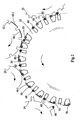
In Fig. 1 ist eine Filteransetzmaschine in einer Vorderansicht ausschnittsweise dargestellt, wobei die Filteransetzmaschine über eine Trommelanordnung T zur Zuführung von Tabakstöcken von einer hier nicht dargestellten Zigarettenstrangmaschine Tabackstöcke doppelter Gebrauchslänge empfängt. Auf ihrem Förderweg zu einer Zusammenstelltrommel 21 werden die Tabakstöcke geschnitten und gespreizt. Auf der Zusammenstelltrommel 21 werden über eine weitere Trommelanordnung M doppeltlange Filterstücke transportiert, die jeweils zwischen zwei längsaxial beabstandete Tabakstöcke eingefügt werden. Hierdurch wird auf der Zusammenstelltrommel 21 eine Folge von queraxial hintereinander angeordneten Zigarette-Mundstück-Zigarette-Gruppen gebildet.In Fig. 1, a Filteransetzmaschine is shown in fragmentary form in a front view, wherein the Filteransetzmaschine via a drum assembly T for feeding tobacco sticks of a Cigarette rod machine, not shown here, receives double-length tobacco sticks. On their conveyor to a
Die zusammengestellten Artikel 50, 60 (siehe Fig. 2 bzw. Fig. 3) auf der Zusammenstelltrommel 21 werden an eine Fördertrommel 22 übergeben und zu einem Belagapparat 10.1 für die erste Gruppe 50 transportiert. In DE-C-39 18 137 ist ausführlich ein Belagapparat beschrieben.The assembled
Der beleimte und geförderte Belagpapierstreifen wird auf einer Schneidtrommel 12.1 von den Messern einer Messertrommel 13.1 in Belagblättchen 40.1 (siehe Fig. 2, 3) zerschnitten. Die geschnittenen Belagblättchen 40.1 werden an die Artikel 50 einer ersten Gruppe auf der Fördertrommel 22 übergeben.The glued and conveyed tipping paper strip is cut on a cutting drum 12.1 by the knives of a knife drum 13.1 in tipping flakes 40.1 (see FIGS. 2, 3). The cut cover sheets 40.1 are transferred to the
Anschließend werden die Artikel 50, 60 (siehe Fig. 2) zu einem Faltstern 23.1 weitertransportiert, der das vordere Ende des Belagpapierblättchens 40.1 an die Artikel 50 anlegt. Nachfolgend werden die Artikel 50, 60 weitergefördert und einer Entnahmetrommel 24 zugeführt, wobei die Entnahmetrommel 24 die Artikel 60 der zweiten Gruppe von der Trommel 22 entnimmt, die nicht mit einem Verbindungsblättchen versehen sind.Subsequently, the
Die Entnahmetrommel 24 übergibt die entnommenen Artikel 60 der zweiten Gruppe an eine Fördertrommel 25, die die Artikel 60 der zweiten Gruppe zu einem zweiten Belagapparat 10.2 transportiert (siehe Fig.2). Der zweite Belagapparat 10.2 verfügt über eine Messerwalze 13.2, die den Belagpapierstreifen im Zusammenwirken mit einer Saugwalze 12.2 schneidet. Die geschnittenen Verbindungsblättchen werden an die Tabakartikel bzw. Zigarette-Mundstück-Zigarette-Gruppen 60 übergeben und angeheftet. Das vordere Ende des Verbindungsblättchens wird danach mittels eines Faltsterns 23.2 an den Artikeln 60 auf der Fördertrommel 25 angelegt. Die Fördertrommel 25 fördert die Artikel 60 der zweiten Gruppe zu einer Trommel 26.The
Die Fördertrommel 26 nimmt gleichzeitig die auf der Fördertrommel 22 weitertransportierten Artikel 50 der ersten Gruppe auf, so dass die Artikel der ersten (50) und der zweiten (60) Gruppe alternierend auf der Trommel 26 angeordnet werden. Nachfolgend werden die Artikel der ersten und der zweiten Gruppe 50, 60 zu einer Rolleinrichtung 27 mit einem Rollklotz transportiert, so dass die Verbindungsblättchen vollständig um die Zigarette-Mundstück-Zigarette-Gruppen 50, 60 herumgewickelt werden. Die fertig umwickelten Artikel 50, 60 werden nachfolgend an eine Fördertrommel 28 und eine weitere Fördertrommel 29 übergeben und für den weiteren Bearbeitungsprozess an einer Filteransetzmaschine bereitgestellt.The
In Fig. 2 ist eine Detailansicht der Förderung von Artikeln einer ersten und einer zweiten Gruppe 50, 60 von Zigarette-Mundstück-Zigarette-Gruppen von der Zusammenstelltrommel 21 zu der Entnahmetrommel 24 im Detail schematisch dargestellt.2, a detailed view of the promotion of articles of a first and a
Von der Zusammenstelltrommel 21 werden Artikel 50, 60 an die Fördertrommel 22 übergeben. Die Fördertrommel 22 verfügt über bewegliche Ärmchen mit Aufnahmemulden für die Artikel 50, 60, so dass der Abstand zwischen den alternierend angeordneten Artikeln 50, 60 veränderbar ist und dabei eine Geschwindigkeitsanpassung der Artikel 50, 60 auf der Fördertrommel 22 an die Geschwindigkeit der Saugwalze 12.1 stattfindet. Dies wird dadurch erreicht, dass vor der Übergabe des Verbindungsblättchens 40.1 an die Artikel 50, 60 die entsprechenden Artikel 50, 60 verlangsamt werden, so dass im Übergabepunkt des Verbindungsblättchens 40.1 an die Artikel 50 das Verbindungsblättchen 40.1 und der jeweilige Artikel 50 die gleiche Geschwindigkeit haben. Nach der Übergabe des Verbindungsblättchens 40.1 werden die Artikel 50, 60 auf der Fördertrommel 22 beschleunigt. Anschließend wird das vordere Ende des Verbindungsblättchens 40.1 mittels des Faltsterns 23.1 an den Artikel 50 angelegt. Während die Artikel 50 mit ihrem Verbindungsblättchen 40.1 auf der Trommel 22 zu der Trommel 26 (Fig. 1) transportiert werden, werden die noch nicht mit einem Verbindungsblättchen versehenen Artikel der zweiten Gruppe 60 von der Entnahmetrommel 24 an eine Fördertrommel 25 (Fig. 1) gefördert.From the
Die Abbrems- und Beschleunigungsvorgänge werden unabhängig von der Fördergeschwindigkeit der Trommel 22 im wesentlichen im Bereich des Übergabepunktes des Verbindungsblättchens 40.1 an die Artikel 50 ausgeführt, jedoch auch zur Anpassung der Geschwindigkeiten bei der Aufnahme bzw. Abgabe der Artikel 50, 60 und dem Anlegen des Belagblättchens 40.1 an die Artikelgruppe 50 ausgeführt.The braking and acceleration operations are carried out independently of the conveying speed of the
In einer hier nicht dargestellten Weiterbildung sind die Ärmchen so ausgebildet, dass mehrere Artikel 50, 60 von einem Ärmchensegment aufgenommen werden. Insbesondere können jeweils ein Artikel der ersten Gruppe und ein Artikel der zweiten Gruppe 60 auf einen Ärmchensegment in Mulden angeordnet werden. Der Abstand der Mulden ist dabei derart ausgebildet, dass bei Anbringen des Belagblättchens 40.1 an die Artikel der ersten Gruppe 50 das freie Ende des Verbindungsblättchens zwischen den Artikeln 50, 60 die vorauseilenden bzw. nacheilenden Artikel jeweils nicht berührt.In a further embodiment, not shown here, the arms are designed so that a plurality of
Durch die Veränderung des Abstandes zwischen den Artikeln der ersten Gruppe 50 und den Artikeln der zweiten Gruppe 60 wird außerdem ein ausreichender Abstand geschaffen, so dass die Verbindungsblättchen 40.1 vom ersten Belagapparat 10.1 an die Artikel 50 angelegt werden, ohne dass die Verbindungsblättchen 40.1 die Artikel der anderen Gruppe 60 berühren.In addition, by changing the distance between the articles of the
In Fig. 3 ist eine alternative Ausführungsform gezeigt, wobei das Anlegen des vorderen Endes des Verbindungsblättchens 40.1 an die Artikel 50 mittels eines Anlegeorgans 33 erfolgt und das Anlegeorgan 33 derart ausgebildet ist, dass die nicht mit einem Verbindungsblättchen versehenen Artikel 60 gleichzeitig entnommen werden. Das Anlegeorgan 33 hat somit die Funktionen des Faltsterns 23.1 aus Fig. 2 und der Entnahmetrommel 24 vereint. Zur Anpassung der Geschwindigkeiten der Artikel 50, 60 relativ zu den Fördergeschwindigkeiten der Verbindungsblättchen 40.1, 40.2 sind auf den Fördertrommeln 22 bzw. 25 Hebelsegmente 35 bzw. 36 vorgesehen, so dass durch das Verschwenken der Hebelsegmente 35 bzw. 36 die Geschwindigkeiten der transportierten Artikel 50, 60 vor dem Übergabepunkt der jeweiligen Verbindungsblättchen 40.1, 40.2 an die Artikel 50, 60 verlangsamt werden und nach der Übergabe der Verbindungsblättchen 40.1, 40.2 beschleunigt werden. Hierfür sind die Trommeln 22, 25 funktionsgleich ausgebildet.In Fig. 3, an alternative embodiment is shown, wherein the application of the front end of the connecting leaflet 40.1 is made to the
Das Hebelsegment 35 der Fördertrommel 22 weist für den Transport der beiden Artikelgruppen 50, 60 jeweils eine Aufnahme für die Artikeigruppe 50 und eine Aufnahme für die Artikelgruppe 60 auf. Der Abstand der Aufnahmemulden auf dem Hebelsegment 35 ist so bestimmt, dass nach Anlegen des Verbindungsblättchens 40.1 das nachlaufende Ende des Verbindungsblättchens 40.1 die hintere Artikelgruppe 60 nicht berührt. Das Hebelsegment 36 der Fördertrommel 25 weist dagegen nur eine Aufnahme für die Artikelgruppe 60, da über den Förderweg der Artikelgruppe 60 die noch nicht mit einem Verbindungsblättchen versehenen Artikel 60 der zweiten Belagvorrichtung 10.2 (siehe Fig. 1) zugeführt werden. Die Hebelsegmente 35, 36 sind auf einem Teilkreis der Fördertrommel 22 bzw. 25 schwenkbar angeordnet und weisen eine zum Trommelinneren sich verjüngende Form auf. Außerdem weisen die Hebelsegmente 35, 36 dornartige Distanzhalter 39 auf, so dass ein Aufliegen der Verbindungsblättchen 40.1, 40.2 auf den Hebelsegmenten verhindert wird.The
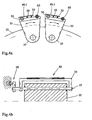
In den Fig. 4a, 4b sind im Ausschnitt die Hebelsegmente 35 der Fördertrommel 22 in einer Vorderansicht bzw. in einer Querschnittsdarstellung gezeigt. Die Hebelsegmente 35 sind mit zwei Aufnahmen für die Artikel 50, 60 ausgebildet, die von der Zusammenstelltrommel 21 übernommen werden. Die Hebelsegmente 35 sind um eine Schwenkachse 37, die parallel zur Drehachse der Trommel 22 ausgerichtet ist, schwenkbar. Die Verschwenkung des Hebelsegmentes 35 während der Rotation der Trommel 22 erfolgt mittels eines Führungsgetriebes 38 (Fig. 4b), bei dem eine Kurvenscheibe in einer Kurvenbahn maschinenseitig geführt wird. Das Hebelsegment 36 der Trommel 25 ist analog und funktionsgleich ausgebildet, wobei Aufnahmen nur für eine Artikelgruppe 60 vorgesehen sind.In FIGS. 4a, 4b, the
Jedes Hebelsegment 35 weist jeweils eine Aufnahmemulde für einen Artikel der ersten Gruppe 50 und einen Artikel der zweiten Gruppe 60 auf. Zwischen den Aufnahmen sind Distanzhalter 39 vorgesehen, die nach Anlegen des Verbindungsblättchens 40.1 an die Artikel der ersten Gruppe 50 ein Aufliegen des Verbindungsblättchens auf das Hebelsegment vermeidet. Der Abstand zwischen den Aufnahmemulden ist so bestimmt, dass das nachlaufende Ende des Verbindungsblättchens 40.1 die Artikelgruppe 60 nicht berührt.Each
In weiteren, hier nicht dargestellten Ausführungsformen können die Artikel 50, 60 auf der Trommel 22 auf radial und/oder tangential beweglichen oder bewegbaren Hebeln angeordnet werden.In further embodiments, not shown here, the
Durch den Gegenstand der vorliegenden Erfindung ist es möglich, die Filteransetzgeschwindigkeit einer Filteransetzmaschine bei einer hohen Formatflexibilität zu erhöhen, da das Belagpapier für die zu umwickelnden Tabakartikel zweibahnig zugeführt wird und die mit einem Verbindungsblättchen versehenen Zigarette-Filter-Zigarette-Gruppen einbahnig auf einer gemeinsamen Rolleinrichtung umrollt werden.By the subject of the present invention, it is possible to increase the Filteransetzgeschwindigkeit a filter tufting machine with a high format flexibility, since the tipping paper for the tobacco to be wrapped tobacco is supplied in two lanes and provided with a compound leaflet cigarette filter cigarette groups in one lane on a common rolling device to be rolled over.
- 10.110.1
- Belagapparatcovering apparatus
- 10.210.2
- Belagapparatcovering apparatus
- 12.112.1
- Saugwalzesuction roll
- 12.212.2
- Saugwalzesuction roll
- 13.113.1
- Messerwalzeknife roll
- 13.213.2
- Messerwalzeknife roll
- 2121
- ZusammenstelltrommelAssembly drum
- 2222
- Fördertrommelconveyor drum
- 23.123.1
- FaltsternFolded Star
- 23.223.2
- FaltsternFolded Star
- 2424
- Entnahmetrommelremoval drum
- 2525
- Fördertrommelconveyor drum
- 2626
- Trommeldrum
- 2727
- Rolleinrichtungrolling device
- 2828
- Trommeldrum
- 2929
- Trommeldrum
- 3333
- Entnahmetrommelremoval drum
- 3535
- Hebelsegmentlever segment
- 3636
- Hebelsegmentlever segment
- 3737
- Schwenkachseswivel axis
- 3838
- Führungsgetriebeguide mechanism
- 3939
- Distanzhalterspacer
- 40.140.1
- Verbindungsblättchenconnecting paper
- 40.240.2
- Verbindungsblättchenconnecting paper
- 5050
- Tabakartikel (Zigarette-Mundstück-Zigarette-Gruppe)Tobacco Articles (Cigarette Mouthpiece Cigarette Group)
- 6060
- Tabakartikel (Zigarette-Mundstück-Zigarette-Gruppe)Tobacco Articles (Cigarette Mouthpiece Cigarette Group)
- MM
- Trommelanordnung (Mundstück)Drum arrangement (mouthpiece)
- TT
- Trommelanordnung (Tabakstöcke)Drum arrangement (Tobacco sticks)
Claims (17)
- Method of combining smoking article components (50, 40.1, 60, 40.2), wherein articles of a first and second group comprising cigarette-filter-cigarette groups (50, 60) are fed in each case to a covering device (10.1, 10.2) and provided in each case with a connection sheet (40.1, 40.2), the articles of the first and second group (50, 60) are fed to a common rolling device (27) and the connection sheets (40.1, 40.2) are wound around the articles of the first and second group (50, 60) in the rolling device (27).
- Method according to claim 1, characterized in that the articles of the first and second group (50, 60) are first fed to the first covering device (10.1), the articles of the first group (50) are provided with a connection sheet by the first covering device (10.1), then the articles of the first and second group (50, 60) are fed along different conveying paths to the common rolling device (27), wherein the articles of the second group (60) along their conveying path are fed to a second covering device (10.2) and provided with a connection sheet.
- Method according to claim 1 or 2, characterized in that the conveying speed of the articles of the first and/or second group (50, 60) is varied upstream and/or downstream of the point of delivery of the respective connection sheet (40.1, 40.2).
- Method according to one of claims 1 to 3, characterized in that the articles of the first and/or second group (50, 60) are decelerated prior to delivery of the connection sheet (40.1, 40.2).
- Method according to one or more of claims 1 to 4, characterized in that the articles of the first and/or second group (50, 60) are accelerated after delivery of the connection sheet (40.1, 40.2).
- Method according to one or more of claims 1 to 5, characterized in that the connection sheet (40.1, 40.2) after delivery are applied partially onto the articles of the first and/or second group (50, 60).
- Method according to one or more of claims 1 to 6, characterized in that the articles of the second group (60) are removed from the common drum conveyor (22) for the articles of the first and second group (50, 60).
- Method according to one or more of claims 1 to 7, characterized in that the articles of the first and second group (50, 60) prior to delivery of the connection sheet (40.1, 40.2) to the first group (50, 60) are disposed alternately on a drum conveyor (22).
- Method according to one or more of claims 1 to 8, - characterized in that the articles of the first and second group (50, 60) during the combining of the article groups are disposed alternately on a drum conveyor (26).
- Method according to one or more of claims 1 to 9, characterized in that the connection sheets (40.1, 40.2) are delivered at a constant speed to the articles of the first and/or second group (50, 60).
- Machine of the tobacco-processing industry, in particular a filter attachment machine, characterized in that for the articles of a first and second group (50, 60) of cigarette-filter-cigarette groups in each case a covering device (10.1, 10.2) and a common rolling device (27) are provided.
- Machine according to claim 11, characterized in that for the covering operation at least one drum conveyor (22, 25) is provided, of which the modular spacings for the articles of the first and/or second group (50, 60) are variable.
- Machine according to claim 12, characterized in that the drum conveyor (22, 25) is designed as a small-armed drum.
- Machine according to claim 12, characterized in that the drum conveyor (22, 25) is provided with, in particular pivotable, lever segments (35, 36).
- Machine according to one or more of claims 11 to 14, characterized in that at least one element (22.1, 23.2, 33) is provided for applying at least one free end of a cover sheet 40.1, 40.2) onto the articles of the first and/or second group (50, 60).
- Machine according to one or more of claims 11 to 15, characterized in that at least one multifunctional drum (33) is provided for the articles of the first and second group 50, 60).
- Machine according to claim 16, characterized in that the multifunctional drum (33) is designed in such a way that at least one free end of a cover sheet (40.1) is applied on an article group (50) and a further article group (60) is removed from the drum conveyor (22).
Priority Applications (11)
| Application Number | Priority Date | Filing Date | Title |
|---|---|---|---|
| AT05017351T ATE412346T1 (en) | 2003-04-11 | 2003-04-11 | CONVEYOR DRUM FOR BAR-SHAPED ITEMS IN THE TOBACCO PROCESSING INDUSTRY |
| AT03008450T ATE327688T1 (en) | 2003-04-11 | 2003-04-11 | METHOD FOR ASSOCIATE SMOKING ARTICLE COMPONENTS |
| EP03008450A EP1466535B1 (en) | 2003-04-11 | 2003-04-11 | Method for assembling components of smoking articles |
| ES03008450T ES2262920T3 (en) | 2003-04-11 | 2003-04-11 | PROCEDURE FOR THE UNION OF COMPONENTS OF SMOKING ITEMS. |
| DE50310723T DE50310723D1 (en) | 2003-04-11 | 2003-04-11 | Conveyor drum for rod-shaped articles of the tobacco processing industry |
| EP05017351A EP1595463B1 (en) | 2003-04-11 | 2003-04-11 | Conveying drum for rod-like articles of the tobacco industry |
| DE50303565T DE50303565D1 (en) | 2003-04-11 | 2003-04-11 | A method of uniting smoking article components |
| US10/817,921 US20040200486A1 (en) | 2003-04-11 | 2004-04-06 | Method for combining smoking article components |
| PL367124A PL210063B1 (en) | 2003-04-11 | 2004-04-08 | Method for bonding tobacco industry product components, machine used in tobacco industry, particularly filter fitting machine, multifunction drum for handling tobacco industry products as well as circular-type magazine for tobacco industry products |
| JP2004114926A JP2004337162A (en) | 2003-04-11 | 2004-04-09 | Method for combining component of smoking article |
| CNB2004100343262A CN100415129C (en) | 2003-04-11 | 2004-04-12 | Method for combining smoking article components |
Applications Claiming Priority (1)
| Application Number | Priority Date | Filing Date | Title |
|---|---|---|---|
| EP03008450A EP1466535B1 (en) | 2003-04-11 | 2003-04-11 | Method for assembling components of smoking articles |
Related Child Applications (1)
| Application Number | Title | Priority Date | Filing Date |
|---|---|---|---|
| EP05017351A Division EP1595463B1 (en) | 2003-04-11 | 2003-04-11 | Conveying drum for rod-like articles of the tobacco industry |
Publications (2)
| Publication Number | Publication Date |
|---|---|
| EP1466535A1 EP1466535A1 (en) | 2004-10-13 |
| EP1466535B1 true EP1466535B1 (en) | 2006-05-31 |
Family
ID=32865004
Family Applications (2)
| Application Number | Title | Priority Date | Filing Date |
|---|---|---|---|
| EP05017351A Expired - Lifetime EP1595463B1 (en) | 2003-04-11 | 2003-04-11 | Conveying drum for rod-like articles of the tobacco industry |
| EP03008450A Expired - Lifetime EP1466535B1 (en) | 2003-04-11 | 2003-04-11 | Method for assembling components of smoking articles |
Family Applications Before (1)
| Application Number | Title | Priority Date | Filing Date |
|---|---|---|---|
| EP05017351A Expired - Lifetime EP1595463B1 (en) | 2003-04-11 | 2003-04-11 | Conveying drum for rod-like articles of the tobacco industry |
Country Status (8)
| Country | Link |
|---|---|
| US (1) | US20040200486A1 (en) |
| EP (2) | EP1595463B1 (en) |
| JP (1) | JP2004337162A (en) |
| CN (1) | CN100415129C (en) |
| AT (2) | ATE327688T1 (en) |
| DE (2) | DE50303565D1 (en) |
| ES (1) | ES2262920T3 (en) |
| PL (1) | PL210063B1 (en) |
Cited By (2)
| Publication number | Priority date | Publication date | Assignee | Title |
|---|---|---|---|---|
| DE102011007091A1 (en) | 2011-04-08 | 2012-10-11 | Hauni Maschinenbau Ag | Device for processing rod-shaped articles in filter setting machine in tobacco processing industry, has pitch changing drum designed such that transfer of articles between changing drum and processing drum takes place with pitch distance |
| CN103491812A (en) * | 2011-04-14 | 2014-01-01 | 豪尼机械制造股份公司 | Conveying rod-like articles in the tobacco-processing industry |
Families Citing this family (12)
| Publication number | Priority date | Publication date | Assignee | Title |
|---|---|---|---|---|
| DE10354135B4 (en) * | 2003-11-19 | 2009-12-10 | Hauni Maschinenbau Ag | Arrangement for the production of filter cigarettes |
| ITBO20040521A1 (en) * | 2004-08-09 | 2004-11-09 | Gd Spa | METHOD AND MACHINE FOR MAKING CIGARETTES WITH FILTER |
| DE102005012810A1 (en) | 2005-03-17 | 2006-10-05 | Hauni Maschinenbau Ag | Process for the production of filter cigarettes |
| DE102005019682A1 (en) * | 2005-04-26 | 2006-11-09 | Hauni Maschinenbau Ag | Feed drum for cigarettes has peripherally separated feed segments with receivers for articles, receivers having separate supports for connecting sheets to articles |
| DE102005027554B4 (en) * | 2005-06-14 | 2007-11-22 | Hauni Maschinenbau Ag | Conveyor drum of the tobacco processing industry with lever segments |
| DE102005031701A1 (en) * | 2005-07-05 | 2007-01-11 | Hauni Maschinenbau Ag | Method for conveying cigarette groups used in the tobacco manufacturing industry comprises detecting an error on a rolling unit and/or conveying unit using a detector and automatically removing the error using an error removal device |
| DE102006019329A1 (en) * | 2006-04-24 | 2007-10-25 | Hauni Maschinenbau Ag | Spacer device for e.g. bobbling drum, of tobacco processing industry, has covering strip section, particularly covering paper strip, supported over preset breadth, where device is formed as spacer strip at segment of conveying drum |
| DE102007002491B3 (en) | 2007-01-11 | 2007-10-11 | Hauni Maschinenbau Ag | Cigarette manufacturing mechanical handling drum imparts longitudinal impulse during transfer to adjacent drum |
| GB0809135D0 (en) | 2008-05-20 | 2008-06-25 | British American Tobacco Co | Apparatus and method for making a smoking article |
| DE102008035383B4 (en) | 2008-07-29 | 2013-02-07 | Hauni Maschinenbau Ag | Conveyor drums of the tobacco processing industry |
| DE102008063847B4 (en) | 2008-12-19 | 2010-08-05 | Hauni Maschinenbau Ag | Swash plate, conveyor drum and machine of the tobacco processing industry |
| US10888110B2 (en) | 2013-03-15 | 2021-01-12 | Hauni Maschinenbau Gmbh | Modular machine for processing and/or testing rod-shaped articles, and related methods |
Family Cites Families (14)
| Publication number | Priority date | Publication date | Assignee | Title |
|---|---|---|---|---|
| DE1173006B (en) * | 1957-01-02 | 1964-06-25 | Hauni Werke Koerber & Co Kg | Device for staggering rod-shaped objects, such as filter rods, to be cut off, such as filter rod parts |
| US3010561A (en) * | 1957-12-26 | 1961-11-28 | Koerber & Co Kg | Filter mouthpiece cigarette making machines |
| GB1046538A (en) * | 1964-08-04 | 1966-10-26 | Tabak & Ind Masch | Apparatus for wrapping sheets around tubes such as cigarettes |
| FR1414956A (en) * | 1964-08-04 | 1965-10-22 | Tabak & Ind Masch | Device for wrapping a small binding sheet around groups preferably formed by a double cigarette mouthpiece and two cigarettes |
| DE1258773B (en) * | 1964-11-14 | 1968-01-11 | Hauni Werke Koerber & Co Kg | Device for wrapping rod-shaped tobacco articles such as cigarettes and filters with a wrapping sheet |
| US4745932A (en) | 1985-07-10 | 1988-05-24 | G.D. Societa Per Azioni | Filter assembly machine |
| US4841993A (en) * | 1987-03-03 | 1989-06-27 | Korber Ag | Method of and machine for making filter cigarettes |
| IT1207721B (en) * | 1987-06-08 | 1989-05-25 | Gd Spa | FILTER FEEDER MACHINE |
| IT1229428B (en) * | 1988-06-11 | 1991-08-08 | Hauni Werke Koerber & Co Kg | CUTTING DEVICE. |
| IT1259802B (en) | 1992-11-20 | 1996-03-26 | Gd Spa | ROLLING DEVICE FOR FILTER FEEDER MACHINES. |
| IT1266304B1 (en) * | 1993-04-23 | 1996-12-27 | Gd Spa | METHOD FOR MAKING FILTER CIGARETTES |
| IT1278160B1 (en) * | 1995-01-17 | 1997-11-17 | Gd Spa | ROLLING UNIT FOR THE CREATION OF CIGARETTES WITH FILTER |
| IT1311424B1 (en) * | 1999-12-13 | 2002-03-12 | Gd Spa | METHOD AND MACHINE FOR THE CREATION OF CIGARETTES WITH FILTER. |
| DE10141703A1 (en) * | 2001-08-25 | 2003-03-06 | Hauni Maschinenbau Ag | Transfer device and method for transferring articles of the tobacco processing industry |
-
2003
- 2003-04-11 AT AT03008450T patent/ATE327688T1/en not_active IP Right Cessation
- 2003-04-11 EP EP05017351A patent/EP1595463B1/en not_active Expired - Lifetime
- 2003-04-11 DE DE50303565T patent/DE50303565D1/en not_active Expired - Lifetime
- 2003-04-11 ES ES03008450T patent/ES2262920T3/en not_active Expired - Lifetime
- 2003-04-11 EP EP03008450A patent/EP1466535B1/en not_active Expired - Lifetime
- 2003-04-11 DE DE50310723T patent/DE50310723D1/en not_active Expired - Lifetime
- 2003-04-11 AT AT05017351T patent/ATE412346T1/en not_active IP Right Cessation
-
2004
- 2004-04-06 US US10/817,921 patent/US20040200486A1/en not_active Abandoned
- 2004-04-08 PL PL367124A patent/PL210063B1/en unknown
- 2004-04-09 JP JP2004114926A patent/JP2004337162A/en not_active Withdrawn
- 2004-04-12 CN CNB2004100343262A patent/CN100415129C/en not_active Expired - Fee Related
Cited By (3)
| Publication number | Priority date | Publication date | Assignee | Title |
|---|---|---|---|---|
| DE102011007091A1 (en) | 2011-04-08 | 2012-10-11 | Hauni Maschinenbau Ag | Device for processing rod-shaped articles in filter setting machine in tobacco processing industry, has pitch changing drum designed such that transfer of articles between changing drum and processing drum takes place with pitch distance |
| CN103491812A (en) * | 2011-04-14 | 2014-01-01 | 豪尼机械制造股份公司 | Conveying rod-like articles in the tobacco-processing industry |
| CN103491812B (en) * | 2011-04-14 | 2016-10-05 | 虹霓机械制造有限公司 | The conveying of the bar form articles of the tobacco industry |
Also Published As
| Publication number | Publication date |
|---|---|
| DE50303565D1 (en) | 2006-07-06 |
| EP1595463B1 (en) | 2008-10-29 |
| US20040200486A1 (en) | 2004-10-14 |
| CN1541576A (en) | 2004-11-03 |
| ATE412346T1 (en) | 2008-11-15 |
| PL367124A1 (en) | 2004-10-18 |
| EP1595463A1 (en) | 2005-11-16 |
| PL210063B1 (en) | 2011-11-30 |
| JP2004337162A (en) | 2004-12-02 |
| DE50310723D1 (en) | 2008-12-11 |
| ES2262920T3 (en) | 2006-12-01 |
| ATE327688T1 (en) | 2006-06-15 |
| CN100415129C (en) | 2008-09-03 |
| EP1466535A1 (en) | 2004-10-13 |
Similar Documents
| Publication | Publication Date | Title |
|---|---|---|
| EP3259999B1 (en) | Transport of rod-shaped articles from the tobacco processing industry | |
| EP1466535B1 (en) | Method for assembling components of smoking articles | |
| EP2659792B1 (en) | Method and apparatus for arranging filter segment groups | |
| EP1715767B1 (en) | Production of filter cigarettes on a double-strip filter positioning machine | |
| WO2012126588A1 (en) | Production of filter plugs and filter cigarettes | |
| EP3685684B1 (en) | The preparation of rod-like smoking products | |
| EP1702523B1 (en) | Method of producing filter-tipped cigarettes | |
| DE102012207582A1 (en) | Production of filter cigarettes | |
| EP1638419B1 (en) | Double-belt filter assembly machine, and production of filter cigarettes | |
| EP1510142B1 (en) | Manipulation of rodlike articles from the tobacco manufacturing industry | |
| DE102005019681A1 (en) | Cigarette paper winding stage, to cover tobacco sticks in cigarette production, moves the sticks into a rolling channel where they are rotated with the paper for winding | |
| DE2622449A1 (en) | METHOD AND DEVICE FOR MANUFACTURING FILTER CIGARETTES | |
| EP2532257B2 (en) | Transport drum for the tobacco processing industry | |
| EP1493341B1 (en) | Double line filter assembling machine | |
| EP2696709B1 (en) | Conveying rod-shaped articles of the tobacco processing industry | |
| EP1588632A1 (en) | Method and device for conveying smoking articles | |
| EP2696707B1 (en) | Conveying rod-shaped articles of the tobacco processing industry | |
| EP1475002B1 (en) | Cigarette-filter assembler with double supply of connecting band | |
| EP2604131A1 (en) | Operation of a filter application machine | |
| EP1849371B1 (en) | Spacer in a conveying drum in the tobacco industry | |
| EP4151098A1 (en) | Rolling of rod-shaped item from the tobacco processing industry | |
| DE946965C (en) | Method and device for the manufacture of mouthpiece cigarettes | |
| DE1047694B (en) | Method and device for the manufacture of mouthpiece cigarettes | |
| DE102004035063A1 (en) | Tobacco stick-filter plug-tobacco stick group combining method for manufacturing cigarette, involves machine-cutting material stripe into connecting lamellae, and placing lamellae one over another on group without any gaps between lamellae |
Legal Events
| Date | Code | Title | Description |
|---|---|---|---|
| PUAI | Public reference made under article 153(3) epc to a published international application that has entered the european phase |
Free format text: ORIGINAL CODE: 0009012 |
|
| AK | Designated contracting states |
Kind code of ref document: A1 Designated state(s): AT BE BG CH CY CZ DE DK EE ES FI FR GB GR HU IE IT LI LU MC NL PT RO SE SI SK TR |
|
| AX | Request for extension of the european patent |
Extension state: AL LT LV MK |
|
| 17P | Request for examination filed |
Effective date: 20050315 |
|
| AKX | Designation fees paid |
Designated state(s): AT BE BG CH CY CZ DE DK EE ES FI FR GB GR HU IE IT LI LU MC NL PT RO SE SI SK TR |
|
| GRAP | Despatch of communication of intention to grant a patent |
Free format text: ORIGINAL CODE: EPIDOSNIGR1 |
|
| GRAS | Grant fee paid |
Free format text: ORIGINAL CODE: EPIDOSNIGR3 |
|
| GRAA | (expected) grant |
Free format text: ORIGINAL CODE: 0009210 |
|
| AK | Designated contracting states |
Kind code of ref document: B1 Designated state(s): AT BE BG CH CY CZ DE DK EE ES FI FR GB GR HU IE IT LI LU MC NL PT RO SE SI SK TR |
|
| PG25 | Lapsed in a contracting state [announced via postgrant information from national office to epo] |
Ref country code: CZ Free format text: LAPSE BECAUSE OF FAILURE TO SUBMIT A TRANSLATION OF THE DESCRIPTION OR TO PAY THE FEE WITHIN THE PRESCRIBED TIME-LIMIT Effective date: 20060531 Ref country code: SK Free format text: LAPSE BECAUSE OF FAILURE TO SUBMIT A TRANSLATION OF THE DESCRIPTION OR TO PAY THE FEE WITHIN THE PRESCRIBED TIME-LIMIT Effective date: 20060531 Ref country code: RO Free format text: LAPSE BECAUSE OF FAILURE TO SUBMIT A TRANSLATION OF THE DESCRIPTION OR TO PAY THE FEE WITHIN THE PRESCRIBED TIME-LIMIT Effective date: 20060531 Ref country code: IT Free format text: LAPSE BECAUSE OF FAILURE TO SUBMIT A TRANSLATION OF THE DESCRIPTION OR TO PAY THE FEE WITHIN THE PRESCRIBED TIME-LIMIT;WARNING: LAPSES OF ITALIAN PATENTS WITH EFFECTIVE DATE BEFORE 2007 MAY HAVE OCCURRED AT ANY TIME BEFORE 2007. THE CORRECT EFFECTIVE DATE MAY BE DIFFERENT FROM THE ONE RECORDED. Effective date: 20060531 Ref country code: SI Free format text: LAPSE BECAUSE OF FAILURE TO SUBMIT A TRANSLATION OF THE DESCRIPTION OR TO PAY THE FEE WITHIN THE PRESCRIBED TIME-LIMIT Effective date: 20060531 Ref country code: IE Free format text: LAPSE BECAUSE OF FAILURE TO SUBMIT A TRANSLATION OF THE DESCRIPTION OR TO PAY THE FEE WITHIN THE PRESCRIBED TIME-LIMIT Effective date: 20060531 Ref country code: FI Free format text: LAPSE BECAUSE OF FAILURE TO SUBMIT A TRANSLATION OF THE DESCRIPTION OR TO PAY THE FEE WITHIN THE PRESCRIBED TIME-LIMIT Effective date: 20060531 |
|
| REG | Reference to a national code |
Ref country code: GB Ref legal event code: FG4D Free format text: NOT ENGLISH Ref country code: CH Ref legal event code: EP |
|
| GBT | Gb: translation of ep patent filed (gb section 77(6)(a)/1977) |
Effective date: 20060531 |
|
| REG | Reference to a national code |
Ref country code: IE Ref legal event code: FG4D Free format text: LANGUAGE OF EP DOCUMENT: GERMAN |
|
| REF | Corresponds to: |
Ref document number: 50303565 Country of ref document: DE Date of ref document: 20060706 Kind code of ref document: P |
|
| PG25 | Lapsed in a contracting state [announced via postgrant information from national office to epo] |
Ref country code: DK Free format text: LAPSE BECAUSE OF FAILURE TO SUBMIT A TRANSLATION OF THE DESCRIPTION OR TO PAY THE FEE WITHIN THE PRESCRIBED TIME-LIMIT Effective date: 20060831 Ref country code: SE Free format text: LAPSE BECAUSE OF FAILURE TO SUBMIT A TRANSLATION OF THE DESCRIPTION OR TO PAY THE FEE WITHIN THE PRESCRIBED TIME-LIMIT Effective date: 20060831 |
|
| REG | Reference to a national code |
Ref country code: HU Ref legal event code: AG4A Ref document number: E000640 Country of ref document: HU |
|
| PG25 | Lapsed in a contracting state [announced via postgrant information from national office to epo] |
Ref country code: PT Free format text: LAPSE BECAUSE OF FAILURE TO SUBMIT A TRANSLATION OF THE DESCRIPTION OR TO PAY THE FEE WITHIN THE PRESCRIBED TIME-LIMIT Effective date: 20061031 |
|
| REG | Reference to a national code |
Ref country code: ES Ref legal event code: FG2A Ref document number: 2262920 Country of ref document: ES Kind code of ref document: T3 |
|
| ET | Fr: translation filed | ||
| REG | Reference to a national code |
Ref country code: IE Ref legal event code: FD4D |
|
| PLBE | No opposition filed within time limit |
Free format text: ORIGINAL CODE: 0009261 |
|
| STAA | Information on the status of an ep patent application or granted ep patent |
Free format text: STATUS: NO OPPOSITION FILED WITHIN TIME LIMIT |
|
| PGFP | Annual fee paid to national office [announced via postgrant information from national office to epo] |
Ref country code: CH Payment date: 20070417 Year of fee payment: 5 |
|
| PGFP | Annual fee paid to national office [announced via postgrant information from national office to epo] |
Ref country code: ES Payment date: 20070418 Year of fee payment: 5 |
|
| PGFP | Annual fee paid to national office [announced via postgrant information from national office to epo] |
Ref country code: HU Payment date: 20070419 Year of fee payment: 5 |
|
| 26N | No opposition filed |
Effective date: 20070301 |
|
| BERE | Be: lapsed |
Owner name: HAUNI MASCHINENBAU A.G. Effective date: 20070430 |
|
| PG25 | Lapsed in a contracting state [announced via postgrant information from national office to epo] |
Ref country code: BE Free format text: LAPSE BECAUSE OF NON-PAYMENT OF DUE FEES Effective date: 20070430 |
|
| PG25 | Lapsed in a contracting state [announced via postgrant information from national office to epo] |
Ref country code: GR Free format text: LAPSE BECAUSE OF FAILURE TO SUBMIT A TRANSLATION OF THE DESCRIPTION OR TO PAY THE FEE WITHIN THE PRESCRIBED TIME-LIMIT Effective date: 20060901 |
|
| PGFP | Annual fee paid to national office [announced via postgrant information from national office to epo] |
Ref country code: FR Payment date: 20070413 Year of fee payment: 5 |
|
| PG25 | Lapsed in a contracting state [announced via postgrant information from national office to epo] |
Ref country code: BG Free format text: LAPSE BECAUSE OF FAILURE TO SUBMIT A TRANSLATION OF THE DESCRIPTION OR TO PAY THE FEE WITHIN THE PRESCRIBED TIME-LIMIT Effective date: 20060831 |
|
| PG25 | Lapsed in a contracting state [announced via postgrant information from national office to epo] |
Ref country code: EE Free format text: LAPSE BECAUSE OF FAILURE TO SUBMIT A TRANSLATION OF THE DESCRIPTION OR TO PAY THE FEE WITHIN THE PRESCRIBED TIME-LIMIT Effective date: 20060531 |
|
| PG25 | Lapsed in a contracting state [announced via postgrant information from national office to epo] |
Ref country code: AT Free format text: LAPSE BECAUSE OF NON-PAYMENT OF DUE FEES Effective date: 20070411 |
|
| REG | Reference to a national code |
Ref country code: CH Ref legal event code: PL |
|
| PG25 | Lapsed in a contracting state [announced via postgrant information from national office to epo] |
Ref country code: HU Free format text: LAPSE BECAUSE OF NON-PAYMENT OF DUE FEES Effective date: 20080412 Ref country code: CH Free format text: LAPSE BECAUSE OF NON-PAYMENT OF DUE FEES Effective date: 20080430 Ref country code: LI Free format text: LAPSE BECAUSE OF NON-PAYMENT OF DUE FEES Effective date: 20080430 |
|
| REG | Reference to a national code |
Ref country code: FR Ref legal event code: ST Effective date: 20081231 |
|
| PG25 | Lapsed in a contracting state [announced via postgrant information from national office to epo] |
Ref country code: MC Free format text: LAPSE BECAUSE OF NON-PAYMENT OF DUE FEES Effective date: 20070430 |
|
| PG25 | Lapsed in a contracting state [announced via postgrant information from national office to epo] |
Ref country code: FR Free format text: LAPSE BECAUSE OF NON-PAYMENT OF DUE FEES Effective date: 20080430 |
|
| REG | Reference to a national code |
Ref country code: ES Ref legal event code: FD2A Effective date: 20080412 |
|
| PG25 | Lapsed in a contracting state [announced via postgrant information from national office to epo] |
Ref country code: ES Free format text: LAPSE BECAUSE OF NON-PAYMENT OF DUE FEES Effective date: 20080412 |
|
| PG25 | Lapsed in a contracting state [announced via postgrant information from national office to epo] |
Ref country code: CY Free format text: LAPSE BECAUSE OF FAILURE TO SUBMIT A TRANSLATION OF THE DESCRIPTION OR TO PAY THE FEE WITHIN THE PRESCRIBED TIME-LIMIT Effective date: 20060531 Ref country code: LU Free format text: LAPSE BECAUSE OF NON-PAYMENT OF DUE FEES Effective date: 20070411 |
|
| PG25 | Lapsed in a contracting state [announced via postgrant information from national office to epo] |
Ref country code: TR Free format text: LAPSE BECAUSE OF FAILURE TO SUBMIT A TRANSLATION OF THE DESCRIPTION OR TO PAY THE FEE WITHIN THE PRESCRIBED TIME-LIMIT Effective date: 20060531 |
|
| PGFP | Annual fee paid to national office [announced via postgrant information from national office to epo] |
Ref country code: GB Payment date: 20130423 Year of fee payment: 11 |
|
| PGFP | Annual fee paid to national office [announced via postgrant information from national office to epo] |
Ref country code: IT Payment date: 20140422 Year of fee payment: 12 Ref country code: NL Payment date: 20140417 Year of fee payment: 12 Ref country code: DE Payment date: 20140423 Year of fee payment: 12 |
|
| GBPC | Gb: european patent ceased through non-payment of renewal fee |
Effective date: 20140411 |
|
| PG25 | Lapsed in a contracting state [announced via postgrant information from national office to epo] |
Ref country code: GB Free format text: LAPSE BECAUSE OF NON-PAYMENT OF DUE FEES Effective date: 20140411 |
|
| REG | Reference to a national code |
Ref country code: DE Ref legal event code: R119 Ref document number: 50303565 Country of ref document: DE |
|
| REG | Reference to a national code |
Ref country code: NL Ref legal event code: MM Effective date: 20150501 |
|
| PG25 | Lapsed in a contracting state [announced via postgrant information from national office to epo] |
Ref country code: DE Free format text: LAPSE BECAUSE OF NON-PAYMENT OF DUE FEES Effective date: 20151103 Ref country code: IT Free format text: LAPSE BECAUSE OF NON-PAYMENT OF DUE FEES Effective date: 20150411 |
|
| PG25 | Lapsed in a contracting state [announced via postgrant information from national office to epo] |
Ref country code: NL Free format text: LAPSE BECAUSE OF NON-PAYMENT OF DUE FEES Effective date: 20150501 |