EP1466110B1 - Satellitengetriebe - Google Patents
Satellitengetriebe Download PDFInfo
- Publication number
- EP1466110B1 EP1466110B1 EP03702446A EP03702446A EP1466110B1 EP 1466110 B1 EP1466110 B1 EP 1466110B1 EP 03702446 A EP03702446 A EP 03702446A EP 03702446 A EP03702446 A EP 03702446A EP 1466110 B1 EP1466110 B1 EP 1466110B1
- Authority
- EP
- European Patent Office
- Prior art keywords
- radial
- satellite
- groove
- load
- grooves
- Prior art date
- Legal status (The legal status is an assumption and is not a legal conclusion. Google has not performed a legal analysis and makes no representation as to the accuracy of the status listed.)
- Expired - Lifetime
Links
- 230000005540 biological transmission Effects 0.000 claims abstract description 45
- 230000033001 locomotion Effects 0.000 claims abstract description 36
- 230000008878 coupling Effects 0.000 claims description 27
- 238000010168 coupling process Methods 0.000 claims description 27
- 238000005859 coupling reaction Methods 0.000 claims description 27
- 230000008859 change Effects 0.000 claims description 8
- 238000005096 rolling process Methods 0.000 claims description 3
- 238000010276 construction Methods 0.000 claims description 2
- 230000000295 complement effect Effects 0.000 claims 1
- 238000012546 transfer Methods 0.000 description 12
- 238000013519 translation Methods 0.000 description 9
- 230000014616 translation Effects 0.000 description 8
- 230000002093 peripheral effect Effects 0.000 description 3
- 230000007704 transition Effects 0.000 description 3
- 238000013016 damping Methods 0.000 description 2
- 238000006073 displacement reaction Methods 0.000 description 2
- 230000000694 effects Effects 0.000 description 2
- 238000005461 lubrication Methods 0.000 description 2
- 230000007246 mechanism Effects 0.000 description 2
- 238000010521 absorption reaction Methods 0.000 description 1
- 230000001133 acceleration Effects 0.000 description 1
- 230000000903 blocking effect Effects 0.000 description 1
- 238000012937 correction Methods 0.000 description 1
- 238000013461 design Methods 0.000 description 1
- 238000011161 development Methods 0.000 description 1
- 238000010586 diagram Methods 0.000 description 1
- 238000007599 discharging Methods 0.000 description 1
- 238000005553 drilling Methods 0.000 description 1
- 238000000034 method Methods 0.000 description 1
- 230000008092 positive effect Effects 0.000 description 1
- 230000008569 process Effects 0.000 description 1
- 230000009467 reduction Effects 0.000 description 1
- 230000000087 stabilizing effect Effects 0.000 description 1
- 238000012549 training Methods 0.000 description 1
Images

Classifications
-
- F—MECHANICAL ENGINEERING; LIGHTING; HEATING; WEAPONS; BLASTING
- F16—ENGINEERING ELEMENTS AND UNITS; GENERAL MEASURES FOR PRODUCING AND MAINTAINING EFFECTIVE FUNCTIONING OF MACHINES OR INSTALLATIONS; THERMAL INSULATION IN GENERAL
- F16H—GEARING
- F16H29/00—Gearings for conveying rotary motion with intermittently-driving members, e.g. with freewheel action
- F16H29/12—Gearings for conveying rotary motion with intermittently-driving members, e.g. with freewheel action between rotary driving and driven members
- F16H29/16—Gearings for conveying rotary motion with intermittently-driving members, e.g. with freewheel action between rotary driving and driven members in which the transmission ratio is changed by adjustment of the distance between the axes of the rotary members
- F16H29/18—Gearings for conveying rotary motion with intermittently-driving members, e.g. with freewheel action between rotary driving and driven members in which the transmission ratio is changed by adjustment of the distance between the axes of the rotary members in which the intermittently-driving members slide along approximately radial guides while rotating with one of the rotary members
-
- Y—GENERAL TAGGING OF NEW TECHNOLOGICAL DEVELOPMENTS; GENERAL TAGGING OF CROSS-SECTIONAL TECHNOLOGIES SPANNING OVER SEVERAL SECTIONS OF THE IPC; TECHNICAL SUBJECTS COVERED BY FORMER USPC CROSS-REFERENCE ART COLLECTIONS [XRACs] AND DIGESTS
- Y10—TECHNICAL SUBJECTS COVERED BY FORMER USPC
- Y10T—TECHNICAL SUBJECTS COVERED BY FORMER US CLASSIFICATION
- Y10T74/00—Machine element or mechanism
- Y10T74/15—Intermittent grip type mechanical movement
- Y10T74/1503—Rotary to intermittent unidirectional motion
Definitions
- the invention relates to a satellite transmission with a drive and an output element, by shifting into any concentric or eccentric one another Locations allow different speed ratios and of those one as an annular disc with a circumferential groove and the other as a star body with Radial grooves is formed, and with satellites that are coupled to the annular disc and via transmission pins the torque in the star body over wear.
- a continuously variable or quasi-continuously adjustable positive-locking Satellite transmission known that a drive and an output element and several individual wheels, which together represent a satellite wheel, which is connected to a central wheel in a permanent positive connection. Become the ratio of the effective radii of the satellite wheel and the central wheel and the mutual eccentric position of the satellite wheel and the central wheel varies with each other by suitable means, the speed ratio is correspondingly determined between the drive and the output element.
- the the Satellite wheel-forming wheels go through in eccentric position to the central wheel a torque transmitting load path and a no-load way cyclically, wherein the wheels on the one hand to the satellite wheel axle and on the other hand via a direction-switched Coupling only rotatably arranged in one direction about its own axis are.
- the transfer Wheels by Form gleicheingriff with blocked self-rotation of each fitting Torque are blocked by Form gleicheingriff with blocked self-rotation of each fitting Torque.
- a nonuniformity of torque transmission is achieved by variation of radii determined by the load arc and / or the effective tangential components At least partially compensated by a cyclical control.
- the coupling elements mounted on the circumference of the drive element and can open the output side by provided there radial grooves different radii taking.
- the coupling elements are doing different, directional switched Force and / or positive effects so engaged that always that coupling element takes over the torque, the highest angular velocity leads in the output element.
- the clamping elements can according to another embodiment described there also contact body having a non-circular cross-section, wherein a surface portion of the Contact body with its radius of curvature about the surface curvature of Ringnutwandung the annular disc is adapted, with the said surface sections the contact body in the torque transmitting position a frictional form a flat system, so that the Hertzian pressure is minimized, the ratio of the radii should be between 0.6 and 1.4.
- a positive overrunning clutch is proposed in which a hollow or Gear of a shaft in the coupling direction is brought into engagement with circulation elements, which are connected to the other shaft, each of the circulating elements brought into positive connection with more than one tooth of the gear becomes.
- the circulation elements lead through the torque-carrying circumferential force on Transfer pin a rotational or sliding movement, bringing it depending on the load direction brought into engagement with the gear or disengaged from the gear become.
- the said translation fluctuations completely or at least partially compensate.
- the radial groove is configured such that at least substantially no movement of the transfer pin in the direction of the center of the star body is possible.
- the radial grooves of the satellites are so long that the total compensation path both in the load arc and in the blank sheet in these radial grooves can expire.
- the star disc is in this case a disc with fixed fixed transmission pins, which slide radially in the grooves on the satellite and in Circumferentially transmitted the torque.
- the radial groove of the satellites is only so long that the balance within the load arc by a sliding movement in this radial groove is reached and the Gleitweg within the blank sheet in grooves of the star wheel or in coupling elements or other similar known transfer elements he follows.
- the diameter of the transfer pin is made larger in the part, which is guided in the groove of the star body as in the part which is in the Radialnut of the satellite is guided.
- the load flank of the groove of the star body through Choice of friction coefficients and / or formed by geometric contouring so that they have a higher sliding or rolling resistance to the contact edges the transmission pin or possibly connected to the transmission pin Sliding blocks than the empty edge and / or in the radial grooves of the satellite conversely, the load flank has a lower resistance than the empty flank.
- An increase of the sliding resistance can be achieved by toothing of the Pen and the groove in the star disc between the opposite flank sides be effected, since the transmission pin or an associated Gleitstein in the load arch always on one side and in the training sheet on the opposite Side is present.
- Another possibility of friction coefficient influencing is a sliding block with sleeves of different radii for each one of to choose both radial grooves, which under load the sliding or rolling resistance in desired meaning is set.
- the transmission pin is inserted in a sliding block, the similar to a clamp body depending on the load direction in one of the two radial grooves locked, so that in the blank sheet or in the load arc, the sliding movement in the desired meaning takes place.
- the transmission pin over a springing in the groove of the satellite in Blank sheet is held at one end so that this groove has enough free space Way for the radial compensation in the load arch is available.
- about the springing will cause the transfer pin within the blank sheet in the star wheel groove slides, since the springing him first of a movement in the satellite groove prevents.
- the peripheral force increases abruptly so that the satellite engages and transmits the applied torque.
- the Sliding motion of the transmission pin in the star disc now experiences an increased Friction, this effect by appropriate design between pin and Groove can be reinforced, so that the sliding resistance in the groove of the satellite less than in the star disc.
- the radial grooves in the star wheel can according to the invention also have a Stop, which has a variably adjustable minimum radius for each gear ratio determines and thus forces the transmission pin, the radial groove on the Use satellites within the load arc for geometric compensation.
- the star disc used had geometrically fixed radial grooves.
- guide elements form, which are mounted on a disc such that a change in width the radial groove is possible depending on the load direction of the transmission pins.
- sliding blocks with the transmission pins are connected and clamped in the load arc to another Prevent radial movement.
- the radial grooves of the star body can also be on separate radial guides be attached, which perform a relative movement on a disc can.
- the radial guides are suspended freely rotatable.
- the Control of the movement of the radial guides is preferably via a Groove 31 of the ring body, whose position relative to the eccentric displacement movement is fixed to the translation regulation.
- the satellites have the principle From DE 199 56 643 A1 known gears, in the load path in a corresponding toothing of the annular disk formed as a ring gear form fit engages, the satellite during the transition from the free path in the load arc and conversely executes a respective pivoting movement.
- the torque acting on the satellite at conceivable unfavorable position of the satellite and with the worst lubrication always larger its than the frictional torque resulting from the frictional force and the distance results in the first intermeshing tooth pair from the satellite axis of rotation Has.
- Carrier writing formed on the individual radial segments are attached to the order can rotate a collinear axis lying to the transmission axis, with one to the Carrier write maintained plane-parallel position.
- this rotation by a springing and / or by a damping a stabilizing moment opposite, so that impact forces in the circumferential direction caused by nonuniformities arise, be cushioned.
- the Pivot ie the axes of rotation of the radial segments on a circumferential line on the Carrier disk on which the satellites at concentric position of the annular disc and the carrier disc, so run at a ratio of 1: 1, so that the Working absorption of springing or damping is greater, the greater the Eccentricity of the carrier disc to the annular disc is.
- the effect of springing becomes 0 for a 1: 1 translation.
- the radial segments are guided by a guide the transmission pin at each eccentric position so guided that they are in essential not to the center of the carrier disc, but to the center show the annular disc.
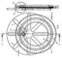
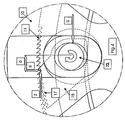
- the satellite transmission shown in principle in FIG. 1 has an annular disk 10, which is designed as a hollow disc with an internal toothing 11.
- This annular disc 10 furthermore has a circumferential groove 12 in which the satellites act as clamping elements be moved circularly.
- the annular disc 10 is to serve as a drive element.
- a star wheel 13 is provided with radial grooves 14.
- the applied torque is transmitted via satellites 15, with their teeth 17 in the coupled state in the toothing 11 of the annular disc form-fitting manner intervention.
- Each satellite will have a molded guide contour 18 in the Circumferential groove 12 out.
- the further molded pin 19 prevents the satellite a reversal of the satellite in the decoupled state, as it reaches a certain angle also starts in the groove 12.
- the inventive radial groove 20 in the satellite allows the pin 21 a compensating movement radially to the annular disc 10. Due to the different diameter of the pin 21 and the different width of the groove 20 in the satellite and the groove 14 in the star wheel rolls this lighter in the radial groove 20 than in the Groove 14, in particular, when it rests against the flank of the groove 14 under load.
- the pin 21 at the end of the groove 20 in the desired end position, i. at the end of the groove 20, holds, so that the movement space is available for radial compensation in the load arc.
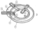
- Radial grooves 36 are connected to the transmission pins 37 with the elements not shown the drive pulley engaged.
- the radial guides 35 can around the Transmission pins 37 rotate, this rotation is controlled by pins 38, the be guided in the cam-like groove 31.
- By the chosen embodiment always guide the radial grooves in the same place, i. in the load arc, a correction movement as a rotation, so that the nonuniformity is reduced.
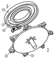
- Fig. 3a to d is the star body not designed with geometrically fixed radial grooves, but owns Instead, on a disc 40 guide members 41 which are connected with brackets 42 are and can rotate around axes 43.
- the position of these axes 43 to each other and the orientation of the brackets 42 is selected so that the between formed in the guide elements 41 radial groove in the transmission pins 52 of the Satellites 50 slide, narrowed as soon as the guide elements 41 about the axes 43 in Rotate the direction of rotation of the gearbox. This rotation is controlled by stops 44 limited.
- each satellite couples 50 When entering the load arc each satellite couples 50, with the load direction changes, so that the guide elements 41, in the freewheeling direction abut one of the stops 44 to rotate the axes 43, while the radial groove get narrower. Because within the radial groove of the relevant transfer pin 52, its rotation is blocked as soon as the groove width becomes smaller is called the diameter of the transmission pin, which is clamped at the same time, so that it prevents its further radial movement. The further compensation movement can thus take place only in the groove 53 of the satellite 50, so that a automatic displacement of the compensating movement takes place during load arch entry. When discharging from the load arch, the described processes proceed analogously in reverse Direction off.
- the rotation of the coupling is accomplished by suitable means Mechanisms in the load arch hinders and thus the relative movement to the satellite groove relocated.
- the radial grooves of the star disk are individually fixed to the disk in this way, that they have a rotational movement and also a combined rotation-translation movement can execute.
- This movement is through a guide pin controlled, which rotates in a cam-shaped circumferential groove on a fixed Disc is fixed.
- the radial grooves thus carry the described movement always at a fixed position relative to the eccentricity, e.g. always starting at the load arch entry and ending at the load arch exit or in the vicinity of it, so that with a suitable contour of the cam groove a reduction in the Nonuniformity is achieved.
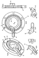
- Fig. 4 shows a satellite 15 with a certain profile of a toothing 17, which is adapted to the toothing 11 of an annular disc.
- the illustration shows the transition from the blank sheet in the load arc, in which the satellite 15 performs a pivoting movement according to arrow 22.
- the circumferential force shown U acts in the direction of the arrow on the eccentric transmission pin 21 on the satellite 15.
- the condition of a secure locking is then satisfied when the torque from the force pair U and Z is greater than the friction torque M r under all conditions, ie in the most unfavorable position of the satellite 15 and in the worst case lubrication.
- the satellite always takes up the full peripheral force only when it is in full meshing (teeth 11, 17) and can never be loaded on the tooth tip.
- the transmission is designed to that the sum of all locking moments (according to arrow direction 22) is always greater than the sum of the opposite torques.
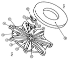
- Fig. 5 shows an annular disc 10 with rotating satellites 15, each by a transmission pin 19, the load-carrying circumferential forces in radial segments 62nd transmitted on a carrier disk 63.
- the axes of rotation 64 allow a Rotation of the radial segments 62, by not shown, but in principle stabilized known spring / damper elements in a 0-position (radial orientation) become.
- the transfer pin 19 is designed so that it is positively in the Ring groove of the annular disc 10 is located and also positively in the corresponding Radialnut a radial segment 62 is guided. In this way, the radial segments become 62 always aligned with the center of the annular disc 10.
Landscapes
- Engineering & Computer Science (AREA)
- General Engineering & Computer Science (AREA)
- Mechanical Engineering (AREA)
- Friction Gearing (AREA)
- Transmission Devices (AREA)
- Transition And Organic Metals Composition Catalysts For Addition Polymerization (AREA)
- Retarders (AREA)
Applications Claiming Priority (3)
| Application Number | Priority Date | Filing Date | Title |
|---|---|---|---|
| DE10201738A DE10201738A1 (de) | 2002-01-18 | 2002-01-18 | Satellitengetriebe |
| DE10201738 | 2002-01-18 | ||
| PCT/EP2003/000355 WO2003060348A1 (de) | 2002-01-18 | 2003-01-15 | Satellitengetriebe |
Publications (2)
| Publication Number | Publication Date |
|---|---|
| EP1466110A1 EP1466110A1 (de) | 2004-10-13 |
| EP1466110B1 true EP1466110B1 (de) | 2005-11-16 |
Family
ID=7712438
Family Applications (1)
| Application Number | Title | Priority Date | Filing Date |
|---|---|---|---|
| EP03702446A Expired - Lifetime EP1466110B1 (de) | 2002-01-18 | 2003-01-15 | Satellitengetriebe |
Country Status (8)
| Country | Link |
|---|---|
| US (1) | US20050120816A1 (enExample) |
| EP (1) | EP1466110B1 (enExample) |
| JP (1) | JP2005515371A (enExample) |
| CN (1) | CN1596350A (enExample) |
| AT (1) | ATE310187T1 (enExample) |
| AU (1) | AU2003205609A1 (enExample) |
| DE (2) | DE10201738A1 (enExample) |
| WO (1) | WO2003060348A1 (enExample) |
Families Citing this family (6)
| Publication number | Priority date | Publication date | Assignee | Title |
|---|---|---|---|---|
| DE102004004850A1 (de) * | 2004-01-30 | 2005-08-18 | Fischer, Ina | Stelltrieb mit Stufenstellung in Satellitengetrieben |
| DE102004004849A1 (de) * | 2004-01-30 | 2005-08-18 | Fischer, Ina | Stufenlos variables, umlaufendes Schaltwechselgetriebe |
| CN103527735B (zh) * | 2013-11-04 | 2017-02-08 | 苏州建莱机械工程技术有限公司 | 行星间歇同步机构 |
| ITUB20156266A1 (it) * | 2015-12-03 | 2017-06-03 | Constantin Edyson Pavilcu | Trasmissione a rapporto di velocita variabile |
| CN106931053A (zh) * | 2017-04-18 | 2017-07-07 | 郭克亚 | 一种楔块式离合器 |
| CN116773673B (zh) * | 2023-08-23 | 2023-10-27 | 广州瑞港消防设备有限公司 | 一种非贮压灭火器罐体检测装置及其检测方法 |
Family Cites Families (8)
| Publication number | Priority date | Publication date | Assignee | Title |
|---|---|---|---|---|
| GB821857A (en) * | 1955-06-22 | 1959-10-14 | Michael Wienand | Improvements in or relating to variable speed torque transmission arrangements |
| US3329031A (en) * | 1964-09-08 | 1967-07-04 | Leon H Maurer | Torque converter |
| US4091684A (en) * | 1974-11-15 | 1978-05-30 | Mathias Bauerle Gmbh | Variable speed control apparatus |
| US5048358A (en) * | 1990-06-04 | 1991-09-17 | Thurston, Inc. | Rotary phased radial thrust variable drive transmission |
| US5653142A (en) * | 1996-02-05 | 1997-08-05 | Kato; Humio | Intermittently rotary gearing |
| US6336887B1 (en) * | 1996-11-21 | 2002-01-08 | Aimbridge Pty Ltd. | Double orbital transmission |
| DE19734962A1 (de) * | 1997-08-13 | 1999-02-18 | Fischer Herwig | Richtungsgeschaltete Kupplung |
| DE19953643B4 (de) * | 1999-11-09 | 2005-02-03 | Innowacja Consulting | Stufenloses Getriebe |
-
2002
- 2002-01-18 DE DE10201738A patent/DE10201738A1/de not_active Withdrawn
-
2003
- 2003-01-15 EP EP03702446A patent/EP1466110B1/de not_active Expired - Lifetime
- 2003-01-15 AT AT03702446T patent/ATE310187T1/de not_active IP Right Cessation
- 2003-01-15 DE DE50301670T patent/DE50301670D1/de not_active Expired - Fee Related
- 2003-01-15 CN CNA038016389A patent/CN1596350A/zh active Pending
- 2003-01-15 US US10/501,615 patent/US20050120816A1/en not_active Abandoned
- 2003-01-15 WO PCT/EP2003/000355 patent/WO2003060348A1/de not_active Ceased
- 2003-01-15 AU AU2003205609A patent/AU2003205609A1/en not_active Abandoned
- 2003-01-15 JP JP2003560406A patent/JP2005515371A/ja active Pending
Also Published As
| Publication number | Publication date |
|---|---|
| US20050120816A1 (en) | 2005-06-09 |
| WO2003060348A1 (de) | 2003-07-24 |
| ATE310187T1 (de) | 2005-12-15 |
| DE10201738A1 (de) | 2003-07-31 |
| JP2005515371A (ja) | 2005-05-26 |
| EP1466110A1 (de) | 2004-10-13 |
| AU2003205609A1 (en) | 2003-07-30 |
| DE50301670D1 (de) | 2005-12-22 |
| CN1596350A (zh) | 2005-03-16 |
Similar Documents
| Publication | Publication Date | Title |
|---|---|---|
| DE60204713T2 (de) | Ein verbessertes stufenloses getriebe | |
| DE3814061C2 (enExample) | ||
| DE69301875T2 (de) | Stufenlos regelbares Keilriemengetriebe | |
| DE8623878U1 (de) | Überlastkupplung | |
| DE4321476C2 (de) | Stufenloses Reibrollengetriebe mit toroidförmigen Reibscheiben | |
| DE69013161T2 (de) | Reibscheibentoroidalgetriebe. | |
| DE3009224C2 (de) | Überlastkupplung | |
| DE69908215T2 (de) | Stufenlos regelbares Toroidgetriebe | |
| EP1003984B1 (de) | Richtungsgeschaltete kupplung | |
| EP0708896B1 (de) | Stufenlos verstellbares formschlüssiges satellitengetriebe | |
| EP1466110B1 (de) | Satellitengetriebe | |
| DE1182011B (de) | Getriebe mit mehreren Zahnraedern | |
| EP1606535A1 (de) | Getriebevorrichtung | |
| DE102011103495A1 (de) | Kupplungswelle,Aktor,Nockenwellenverstellgetriebe und Nockenwellensteller | |
| DE3341558A1 (de) | Taumelplanradgetriebe | |
| DE3623142C2 (enExample) | ||
| DE19953643B4 (de) | Stufenloses Getriebe | |
| EP3187751A1 (de) | Stufenloses planetengetriebe | |
| DE2458762A1 (de) | Reibrad-planetengetriebe | |
| EP1019645B1 (de) | Getriebe mit stufenlos einstellbarer übersetzung | |
| EP2839187B1 (de) | Stufenloses getriebe | |
| DE19743483C2 (de) | Getriebe mit stufenlos einstellbarer Übersetzung | |
| WO2002053949A2 (de) | Stufenlos verstellbares getriebe | |
| DE3307824A1 (de) | Vorrichtung zum reibschluessigen kuppeln zweier koaxialer, drehbeweglicher teile | |
| DE3875198T2 (de) | Eingeschriebene getriebevorrichtung. |
Legal Events
| Date | Code | Title | Description |
|---|---|---|---|
| PUAI | Public reference made under article 153(3) epc to a published international application that has entered the european phase |
Free format text: ORIGINAL CODE: 0009012 |
|
| 17P | Request for examination filed |
Effective date: 20040703 |
|
| AK | Designated contracting states |
Kind code of ref document: A1 Designated state(s): AT BE BG CH CY CZ DE DK EE ES FI FR GB GR HU IE IT LI LU MC NL PT SE SI SK TR |
|
| AX | Request for extension of the european patent |
Extension state: AL LT LV MK RO |
|
| RIN1 | Information on inventor provided before grant (corrected) |
Inventor name: FISCHER, HERWIG |
|
| GRAP | Despatch of communication of intention to grant a patent |
Free format text: ORIGINAL CODE: EPIDOSNIGR1 |
|
| GRAS | Grant fee paid |
Free format text: ORIGINAL CODE: EPIDOSNIGR3 |
|
| GRAA | (expected) grant |
Free format text: ORIGINAL CODE: 0009210 |
|
| AK | Designated contracting states |
Kind code of ref document: B1 Designated state(s): AT BE BG CH CY CZ DE DK EE ES FI FR GB GR HU IE IT LI LU MC NL PT SE SI SK TR |
|
| PG25 | Lapsed in a contracting state [announced via postgrant information from national office to epo] |
Ref country code: IT Free format text: LAPSE BECAUSE OF FAILURE TO SUBMIT A TRANSLATION OF THE DESCRIPTION OR TO PAY THE FEE WITHIN THE PRESCRIBED TIME-LIMIT;WARNING: LAPSES OF ITALIAN PATENTS WITH EFFECTIVE DATE BEFORE 2007 MAY HAVE OCCURRED AT ANY TIME BEFORE 2007. THE CORRECT EFFECTIVE DATE MAY BE DIFFERENT FROM THE ONE RECORDED. Effective date: 20051116 Ref country code: IE Free format text: LAPSE BECAUSE OF FAILURE TO SUBMIT A TRANSLATION OF THE DESCRIPTION OR TO PAY THE FEE WITHIN THE PRESCRIBED TIME-LIMIT Effective date: 20051116 Ref country code: GB Free format text: LAPSE BECAUSE OF FAILURE TO SUBMIT A TRANSLATION OF THE DESCRIPTION OR TO PAY THE FEE WITHIN THE PRESCRIBED TIME-LIMIT Effective date: 20051116 Ref country code: SK Free format text: LAPSE BECAUSE OF FAILURE TO SUBMIT A TRANSLATION OF THE DESCRIPTION OR TO PAY THE FEE WITHIN THE PRESCRIBED TIME-LIMIT Effective date: 20051116 Ref country code: SI Free format text: LAPSE BECAUSE OF FAILURE TO SUBMIT A TRANSLATION OF THE DESCRIPTION OR TO PAY THE FEE WITHIN THE PRESCRIBED TIME-LIMIT Effective date: 20051116 Ref country code: NL Free format text: LAPSE BECAUSE OF FAILURE TO SUBMIT A TRANSLATION OF THE DESCRIPTION OR TO PAY THE FEE WITHIN THE PRESCRIBED TIME-LIMIT Effective date: 20051116 Ref country code: FI Free format text: LAPSE BECAUSE OF FAILURE TO SUBMIT A TRANSLATION OF THE DESCRIPTION OR TO PAY THE FEE WITHIN THE PRESCRIBED TIME-LIMIT Effective date: 20051116 Ref country code: CZ Free format text: LAPSE BECAUSE OF FAILURE TO SUBMIT A TRANSLATION OF THE DESCRIPTION OR TO PAY THE FEE WITHIN THE PRESCRIBED TIME-LIMIT Effective date: 20051116 |
|
| REG | Reference to a national code |
Ref country code: GB Ref legal event code: FG4D Free format text: NOT ENGLISH |
|
| REG | Reference to a national code |
Ref country code: CH Ref legal event code: EP |
|
| REF | Corresponds to: |
Ref document number: 50301670 Country of ref document: DE Date of ref document: 20051222 Kind code of ref document: P |
|
| REG | Reference to a national code |
Ref country code: IE Ref legal event code: FG4D Free format text: LANGUAGE OF EP DOCUMENT: GERMAN |
|
| PG25 | Lapsed in a contracting state [announced via postgrant information from national office to epo] |
Ref country code: MC Free format text: LAPSE BECAUSE OF NON-PAYMENT OF DUE FEES Effective date: 20060131 Ref country code: LU Free format text: LAPSE BECAUSE OF NON-PAYMENT OF DUE FEES Effective date: 20060131 Ref country code: BE Free format text: LAPSE BECAUSE OF NON-PAYMENT OF DUE FEES Effective date: 20060131 |
|
| PG25 | Lapsed in a contracting state [announced via postgrant information from national office to epo] |
Ref country code: DK Free format text: LAPSE BECAUSE OF FAILURE TO SUBMIT A TRANSLATION OF THE DESCRIPTION OR TO PAY THE FEE WITHIN THE PRESCRIBED TIME-LIMIT Effective date: 20060216 Ref country code: SE Free format text: LAPSE BECAUSE OF FAILURE TO SUBMIT A TRANSLATION OF THE DESCRIPTION OR TO PAY THE FEE WITHIN THE PRESCRIBED TIME-LIMIT Effective date: 20060216 Ref country code: BG Free format text: LAPSE BECAUSE OF FAILURE TO SUBMIT A TRANSLATION OF THE DESCRIPTION OR TO PAY THE FEE WITHIN THE PRESCRIBED TIME-LIMIT Effective date: 20060216 Ref country code: GR Free format text: LAPSE BECAUSE OF FAILURE TO SUBMIT A TRANSLATION OF THE DESCRIPTION OR TO PAY THE FEE WITHIN THE PRESCRIBED TIME-LIMIT Effective date: 20060216 |
|
| PG25 | Lapsed in a contracting state [announced via postgrant information from national office to epo] |
Ref country code: ES Free format text: LAPSE BECAUSE OF FAILURE TO SUBMIT A TRANSLATION OF THE DESCRIPTION OR TO PAY THE FEE WITHIN THE PRESCRIBED TIME-LIMIT Effective date: 20060227 |
|
| PG25 | Lapsed in a contracting state [announced via postgrant information from national office to epo] |
Ref country code: PT Free format text: LAPSE BECAUSE OF FAILURE TO SUBMIT A TRANSLATION OF THE DESCRIPTION OR TO PAY THE FEE WITHIN THE PRESCRIBED TIME-LIMIT Effective date: 20060417 |
|
| NLV1 | Nl: lapsed or annulled due to failure to fulfill the requirements of art. 29p and 29m of the patents act | ||
| PG25 | Lapsed in a contracting state [announced via postgrant information from national office to epo] |
Ref country code: HU Free format text: LAPSE BECAUSE OF FAILURE TO SUBMIT A TRANSLATION OF THE DESCRIPTION OR TO PAY THE FEE WITHIN THE PRESCRIBED TIME-LIMIT Effective date: 20060517 |
|
| GBV | Gb: ep patent (uk) treated as always having been void in accordance with gb section 77(7)/1977 [no translation filed] |
Effective date: 20051116 |
|
| REG | Reference to a national code |
Ref country code: IE Ref legal event code: FD4D |
|
| ET | Fr: translation filed | ||
| PLBE | No opposition filed within time limit |
Free format text: ORIGINAL CODE: 0009261 |
|
| STAA | Information on the status of an ep patent application or granted ep patent |
Free format text: STATUS: NO OPPOSITION FILED WITHIN TIME LIMIT |
|
| 26N | No opposition filed |
Effective date: 20060817 |
|
| PGFP | Annual fee paid to national office [announced via postgrant information from national office to epo] |
Ref country code: AT Payment date: 20070111 Year of fee payment: 5 |
|
| PG25 | Lapsed in a contracting state [announced via postgrant information from national office to epo] |
Ref country code: LI Free format text: LAPSE BECAUSE OF NON-PAYMENT OF DUE FEES Effective date: 20070131 Ref country code: CH Free format text: LAPSE BECAUSE OF NON-PAYMENT OF DUE FEES Effective date: 20070131 |
|
| PGFP | Annual fee paid to national office [announced via postgrant information from national office to epo] |
Ref country code: DE Payment date: 20070206 Year of fee payment: 5 |
|
| REG | Reference to a national code |
Ref country code: CH Ref legal event code: PL |
|
| BERE | Be: lapsed |
Owner name: SATELLITE GEAR SYSTEM LTD. Effective date: 20060131 |
|
| PGFP | Annual fee paid to national office [announced via postgrant information from national office to epo] |
Ref country code: FR Payment date: 20070111 Year of fee payment: 5 |
|
| PG25 | Lapsed in a contracting state [announced via postgrant information from national office to epo] |
Ref country code: EE Free format text: LAPSE BECAUSE OF FAILURE TO SUBMIT A TRANSLATION OF THE DESCRIPTION OR TO PAY THE FEE WITHIN THE PRESCRIBED TIME-LIMIT Effective date: 20051116 |
|
| PG25 | Lapsed in a contracting state [announced via postgrant information from national office to epo] |
Ref country code: TR Free format text: LAPSE BECAUSE OF FAILURE TO SUBMIT A TRANSLATION OF THE DESCRIPTION OR TO PAY THE FEE WITHIN THE PRESCRIBED TIME-LIMIT Effective date: 20051116 |
|
| PG25 | Lapsed in a contracting state [announced via postgrant information from national office to epo] |
Ref country code: DE Free format text: LAPSE BECAUSE OF NON-PAYMENT OF DUE FEES Effective date: 20080801 |
|
| PG25 | Lapsed in a contracting state [announced via postgrant information from national office to epo] |
Ref country code: CY Free format text: LAPSE BECAUSE OF FAILURE TO SUBMIT A TRANSLATION OF THE DESCRIPTION OR TO PAY THE FEE WITHIN THE PRESCRIBED TIME-LIMIT Effective date: 20051116 Ref country code: AT Free format text: LAPSE BECAUSE OF NON-PAYMENT OF DUE FEES Effective date: 20080115 |
|
| REG | Reference to a national code |
Ref country code: FR Ref legal event code: ST Effective date: 20081029 |
|
| PG25 | Lapsed in a contracting state [announced via postgrant information from national office to epo] |
Ref country code: FR Free format text: LAPSE BECAUSE OF NON-PAYMENT OF DUE FEES Effective date: 20080131 |