EP1465432B1 - Appareil de codage d'images mobiles, appareil de decodage d'images mobiles, procede de codage d'images mobiles, procede de decodage d'images mobiles, programme et support lisible par ordinateur contenant le programme - Google Patents
Appareil de codage d'images mobiles, appareil de decodage d'images mobiles, procede de codage d'images mobiles, procede de decodage d'images mobiles, programme et support lisible par ordinateur contenant le programme Download PDFInfo
- Publication number
- EP1465432B1 EP1465432B1 EP02783711.1A EP02783711A EP1465432B1 EP 1465432 B1 EP1465432 B1 EP 1465432B1 EP 02783711 A EP02783711 A EP 02783711A EP 1465432 B1 EP1465432 B1 EP 1465432B1
- Authority
- EP
- European Patent Office
- Prior art keywords
- motion vector
- section
- predetermined
- picture
- predicted
- Prior art date
- Legal status (The legal status is an assumption and is not a legal conclusion. Google has not performed a legal analysis and makes no representation as to the accuracy of the status listed.)
- Expired - Fee Related
Links
Images


Classifications
-
- H—ELECTRICITY
- H04—ELECTRIC COMMUNICATION TECHNIQUE
- H04N—PICTORIAL COMMUNICATION, e.g. TELEVISION
- H04N9/00—Details of colour television systems
- H04N9/79—Processing of colour television signals in connection with recording
- H04N9/80—Transformation of the television signal for recording, e.g. modulation, frequency changing; Inverse transformation for playback
- H04N9/804—Transformation of the television signal for recording, e.g. modulation, frequency changing; Inverse transformation for playback involving pulse code modulation of the colour picture signal components
- H04N9/8042—Transformation of the television signal for recording, e.g. modulation, frequency changing; Inverse transformation for playback involving pulse code modulation of the colour picture signal components involving data reduction
-
- H—ELECTRICITY
- H04—ELECTRIC COMMUNICATION TECHNIQUE
- H04N—PICTORIAL COMMUNICATION, e.g. TELEVISION
- H04N19/00—Methods or arrangements for coding, decoding, compressing or decompressing digital video signals
- H04N19/10—Methods or arrangements for coding, decoding, compressing or decompressing digital video signals using adaptive coding
- H04N19/102—Methods or arrangements for coding, decoding, compressing or decompressing digital video signals using adaptive coding characterised by the element, parameter or selection affected or controlled by the adaptive coding
- H04N19/103—Selection of coding mode or of prediction mode
- H04N19/105—Selection of the reference unit for prediction within a chosen coding or prediction mode, e.g. adaptive choice of position and number of pixels used for prediction
-
- H—ELECTRICITY
- H04—ELECTRIC COMMUNICATION TECHNIQUE
- H04N—PICTORIAL COMMUNICATION, e.g. TELEVISION
- H04N19/00—Methods or arrangements for coding, decoding, compressing or decompressing digital video signals
- H04N19/10—Methods or arrangements for coding, decoding, compressing or decompressing digital video signals using adaptive coding
- H04N19/102—Methods or arrangements for coding, decoding, compressing or decompressing digital video signals using adaptive coding characterised by the element, parameter or selection affected or controlled by the adaptive coding
- H04N19/117—Filters, e.g. for pre-processing or post-processing
-
- H—ELECTRICITY
- H04—ELECTRIC COMMUNICATION TECHNIQUE
- H04N—PICTORIAL COMMUNICATION, e.g. TELEVISION
- H04N19/00—Methods or arrangements for coding, decoding, compressing or decompressing digital video signals
- H04N19/10—Methods or arrangements for coding, decoding, compressing or decompressing digital video signals using adaptive coding
- H04N19/134—Methods or arrangements for coding, decoding, compressing or decompressing digital video signals using adaptive coding characterised by the element, parameter or criterion affecting or controlling the adaptive coding
- H04N19/136—Incoming video signal characteristics or properties
- H04N19/137—Motion inside a coding unit, e.g. average field, frame or block difference
- H04N19/139—Analysis of motion vectors, e.g. their magnitude, direction, variance or reliability
-
- H—ELECTRICITY
- H04—ELECTRIC COMMUNICATION TECHNIQUE
- H04N—PICTORIAL COMMUNICATION, e.g. TELEVISION
- H04N19/00—Methods or arrangements for coding, decoding, compressing or decompressing digital video signals
- H04N19/10—Methods or arrangements for coding, decoding, compressing or decompressing digital video signals using adaptive coding
- H04N19/134—Methods or arrangements for coding, decoding, compressing or decompressing digital video signals using adaptive coding characterised by the element, parameter or criterion affecting or controlling the adaptive coding
- H04N19/157—Assigned coding mode, i.e. the coding mode being predefined or preselected to be further used for selection of another element or parameter
-
- H—ELECTRICITY
- H04—ELECTRIC COMMUNICATION TECHNIQUE
- H04N—PICTORIAL COMMUNICATION, e.g. TELEVISION
- H04N19/00—Methods or arrangements for coding, decoding, compressing or decompressing digital video signals
- H04N19/10—Methods or arrangements for coding, decoding, compressing or decompressing digital video signals using adaptive coding
- H04N19/169—Methods or arrangements for coding, decoding, compressing or decompressing digital video signals using adaptive coding characterised by the coding unit, i.e. the structural portion or semantic portion of the video signal being the object or the subject of the adaptive coding
- H04N19/17—Methods or arrangements for coding, decoding, compressing or decompressing digital video signals using adaptive coding characterised by the coding unit, i.e. the structural portion or semantic portion of the video signal being the object or the subject of the adaptive coding the unit being an image region, e.g. an object
-
- H—ELECTRICITY
- H04—ELECTRIC COMMUNICATION TECHNIQUE
- H04N—PICTORIAL COMMUNICATION, e.g. TELEVISION
- H04N19/00—Methods or arrangements for coding, decoding, compressing or decompressing digital video signals
- H04N19/50—Methods or arrangements for coding, decoding, compressing or decompressing digital video signals using predictive coding
- H04N19/503—Methods or arrangements for coding, decoding, compressing or decompressing digital video signals using predictive coding involving temporal prediction
- H04N19/51—Motion estimation or motion compensation
- H04N19/523—Motion estimation or motion compensation with sub-pixel accuracy
-
- H—ELECTRICITY
- H04—ELECTRIC COMMUNICATION TECHNIQUE
- H04N—PICTORIAL COMMUNICATION, e.g. TELEVISION
- H04N19/00—Methods or arrangements for coding, decoding, compressing or decompressing digital video signals
- H04N19/50—Methods or arrangements for coding, decoding, compressing or decompressing digital video signals using predictive coding
- H04N19/503—Methods or arrangements for coding, decoding, compressing or decompressing digital video signals using predictive coding involving temporal prediction
- H04N19/51—Motion estimation or motion compensation
- H04N19/53—Multi-resolution motion estimation; Hierarchical motion estimation
-
- H—ELECTRICITY
- H04—ELECTRIC COMMUNICATION TECHNIQUE
- H04N—PICTORIAL COMMUNICATION, e.g. TELEVISION
- H04N19/00—Methods or arrangements for coding, decoding, compressing or decompressing digital video signals
- H04N19/50—Methods or arrangements for coding, decoding, compressing or decompressing digital video signals using predictive coding
- H04N19/503—Methods or arrangements for coding, decoding, compressing or decompressing digital video signals using predictive coding involving temporal prediction
- H04N19/51—Motion estimation or motion compensation
- H04N19/56—Motion estimation with initialisation of the vector search, e.g. estimating a good candidate to initiate a search
-
- H—ELECTRICITY
- H04—ELECTRIC COMMUNICATION TECHNIQUE
- H04N—PICTORIAL COMMUNICATION, e.g. TELEVISION
- H04N19/00—Methods or arrangements for coding, decoding, compressing or decompressing digital video signals
- H04N19/50—Methods or arrangements for coding, decoding, compressing or decompressing digital video signals using predictive coding
- H04N19/503—Methods or arrangements for coding, decoding, compressing or decompressing digital video signals using predictive coding involving temporal prediction
- H04N19/51—Motion estimation or motion compensation
- H04N19/577—Motion compensation with bidirectional frame interpolation, i.e. using B-pictures
-
- H—ELECTRICITY
- H04—ELECTRIC COMMUNICATION TECHNIQUE
- H04N—PICTORIAL COMMUNICATION, e.g. TELEVISION
- H04N19/00—Methods or arrangements for coding, decoding, compressing or decompressing digital video signals
- H04N19/50—Methods or arrangements for coding, decoding, compressing or decompressing digital video signals using predictive coding
- H04N19/59—Methods or arrangements for coding, decoding, compressing or decompressing digital video signals using predictive coding involving spatial sub-sampling or interpolation, e.g. alteration of picture size or resolution
-
- H—ELECTRICITY
- H04—ELECTRIC COMMUNICATION TECHNIQUE
- H04N—PICTORIAL COMMUNICATION, e.g. TELEVISION
- H04N19/00—Methods or arrangements for coding, decoding, compressing or decompressing digital video signals
- H04N19/50—Methods or arrangements for coding, decoding, compressing or decompressing digital video signals using predictive coding
- H04N19/593—Methods or arrangements for coding, decoding, compressing or decompressing digital video signals using predictive coding involving spatial prediction techniques
-
- H—ELECTRICITY
- H04—ELECTRIC COMMUNICATION TECHNIQUE
- H04N—PICTORIAL COMMUNICATION, e.g. TELEVISION
- H04N19/00—Methods or arrangements for coding, decoding, compressing or decompressing digital video signals
- H04N19/60—Methods or arrangements for coding, decoding, compressing or decompressing digital video signals using transform coding
- H04N19/61—Methods or arrangements for coding, decoding, compressing or decompressing digital video signals using transform coding in combination with predictive coding
-
- H—ELECTRICITY
- H04—ELECTRIC COMMUNICATION TECHNIQUE
- H04N—PICTORIAL COMMUNICATION, e.g. TELEVISION
- H04N19/00—Methods or arrangements for coding, decoding, compressing or decompressing digital video signals
- H04N19/70—Methods or arrangements for coding, decoding, compressing or decompressing digital video signals characterised by syntax aspects related to video coding, e.g. related to compression standards
Definitions
- the present invention relates to a moving picture encoding device, a moving picture decoding device, a moving picture encoding method, a moving picture decoding method, a program, and a computer readable recording medium which has stored the program.
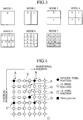
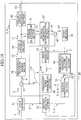
- FIG. 1 shows a configuration of the aforementioned moving picture encoding device 20
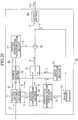
- FIG. 2 shows a configuration of the aforementioned moving picture decoding device 50.
- the moving picture encoding device shown in FIG. 1 reduces a redundancy present in a time direction by motion compensation inter-frame prediction, and further reduces a redundancy left in a space direction by orthogonal transformation, so as to execute information compression of a moving picture (an input video signal).
- FIG. 3 shows an explanatory diagram of the motion compensation inter-frame prediction.
- An input video signal 1 is constituted of a time sequence of frame pictures.
- the frame picture to be encoded is divided into square rectangular areas (macro-blocks) of 16x16 pixels, and an encoding process in the moving picture encoding device 20 and a decoding process in the moving picture decoding device 50 are carried out by units of these macro-blocks.
- the frame picture which is divided into the macro-block units is defined as "a frame picture signal 2".
- prediction modes are an "INTRA prediction mode” for executing space prediction which uses pixel values of encoded neighboring areas on the same frame picture (e.g., pixel values adjacent to the upper and left sides of a frame picture signal 2 to be encoded), and a plurality of "INTER prediction modes” for executing motion compensation inter-frame prediction which uses encoded frame pictures (reference frame pictures 5) different with time.
- the "H. 26L encoding system” is configured such that efficient information compression can be carried out by switching the "prediction mode" by a macro-block unit, in accordance with a local nature of the input video signal 1.
- the "motion compensation inter-frame prediction” is a technology for searching an picture signal pattern similar to an picture signal pattern in the frame picture signal 2 within a predetermined search range of a reference frame picture 5, for detecting a spatial displacement amount between both picture signal patterns as a "motion vector 3", and for encoding and transmitting "motion compensation related information” containing the "motion vector 3," the "prediction mode” and a “reference frame number,” as well as a “predicted residual signal 9" calculated in accordance with the motion vector 3.
- a "skip mode” useful when a video is static i.e., a prediction mode for directly copying a pixel in the same position of the reference frame picture 5 (the encoded frame picture) as it is.
- the motion vector 3 is detected by a unit of 16x16 pixels on a "mode 1", by a unit of 8 ⁇ 16 pixels on a "mode 2", by a unit of 16x8 pixels on a “mode 3", by a unit of 8x8 pixels on a "mode 4", by a unit of 4x8 pixels on a "mode 5", by a unit of 8x4 pixels on a "mode 6", and by a unit of 4x4 pixels on a "mode 7".
- these 7 kinds of prediction modes enable subdivision of motion detection units in the macro-block, and are disposed for the purpose of accurately grasping various motions that can be present in the macro-block.
- an input section 31 transmits the frame picture signal 2 to a motion detection section 32 and a space prediction section 35.
- the motion detection section 32 detects the number of motion vectors 3 corresponding to a predetermined prediction mode 4 for the received frame picture signal 2, by referring to the reference frame picture 5 sent from a frame memory 34.
- the space prediction section 35 carries out space prediction that uses pixel values of encoded neighboring areas on the same frame picture sent from the frame memory 34.
- the space prediction section 35 may execute space prediction by a plurality of methods.
- the motion detection section 32 transmits motion vectors 3 detected for all the "INTER prediction modes" shown in FIG. 3 , and the prediction modes (e.g., modes 1 to 7) 4 corresponding to the motion vectors 3, to a motion compensation section 33.
- the prediction modes e.g., modes 1 to 7
- the motion compensation section 33 generates a predicted picture signal (a macro-block unit) 6, by motion compensation which uses the reference frame picture 5 sent from the frame memory 34 and a combination of the plurality of motion vectors 3 and prediction modes 4 sent from the motion detection section 32.
- the motion compensation section 33 transmits information regarding the predicted picture signal 6 generated by the motion compensation, the prediction mode 4, the motion vectors 3 and encoding efficiency, to a prediction mode determining section 36.
- the space prediction section 35 transmits information regarding a predicted picture signal 7 generated by space prediction, the prediction mode (if there are a plurality of kinds of space prediction) 4 and encoding efficiency, to the prediction mode determining section 36.
- the prediction mode determining section 36 evaluates all the "INTER prediction modes" shown in FIG. 3 by a macro-block unit, so as to select an "INTER prediction mode" which is determined to be highest in encoding efficiency.
- the prediction mode determining section 36 similarly evaluates the "INTRA prediction modes", and selects the "INTRA prediction mode” if the "INTRA prediction mode" is higher in encoding efficiency than the "INTER prediction mode".
- the prediction mode determining section 36 transmits a predicted picture signal (a macro-block unit) 8 generated by the selected prediction mode 4, to a subtracter 37.
- the prediction mode determining section 36 transmits "motion compensation related information" containing the number (up to 16 per macro-block) of motion vectors 3 or the like set on the selected "INTER prediction mode", to a variable length encoding section 40.
- the prediction mode determining section 36 transmits no motion vectors 3.
- an orthogonal transformation section 38 generates an orthogonal transformation coefficient 10, by applying orthogonal transformation to a difference value (a predicted residual signal 9) between the frame picture signal 2 and the predicted picture signal 8 sent from the subtracter 37.
- a quantization section 39 generates a quantized orthogonal transformation coefficient 11, by quantizing the orthogonal transformation coefficient 10 sent from the orthogonal transformation section 38.
- variable length encoding section 40 carries out entropy encoding for the quantized orthogonal transformation coefficient 11 sent from the quantization section 39 and the prediction mode 4 (and motion vectors 3) sent from the prediction mode determining section 36, so as to multiplex them into a compressed stream 12.
- variable length encoding section 40 may transmit the compressed stream 12 to a moving picture decoding device 50 by a macro-block unit, or transmit the compressed stream 12 by a frame picture unit.
- an inverse quantization section 41 generates an orthogonal transformation coefficient 13, by carrying out inverse quantization for the quantized orthogonal transformation coefficient 11 sent from the quantization section 39. Then, an inverse orthogonal transformation section 42 generates a predicted residual signal 14, by carrying out inverse orthogonal transformation for the orthogonal transformation coefficient 13 sent from the inverse quantization section 41.
- the predicted residual signal 14 sent from the inverse orthogonal transformation section 42 and the predicted picture signal 8 sent from the prediction mode determining section 36 are added together to generate a frame picture signal 15.
- This frame picture signal 15 of a macro-block unit is stored in the frame memory 34.
- the frame memory 34 there have been stored a reference frame picture 5 of a frame picture unit used for a subsequent encoding process, and information (a pixel value or a motion vector) of an encoded macro-block of a frame picture which is currently being encoded.
- variable length decoding section 71 detects a synchronous word indicating a head of each frame, and restores the motion vector 3, the prediction mode 4 and the quantized orthogonal transformation coefficient 11 for each macro-block unit.
- variable length decoding section 71 transmits the quantized orthogonal transformation coefficient 11 to an inverse quantization section 76, and transmits the prediction mode 4 to a switch 75. Additionally, the variable length decoding section 71 transmits the motion vector 3 and the prediction mode 4 to a motion compensation section 72 when the prediction mode 4 is an "INTER prediction mode", and transmits the prediction mode 4 to a space prediction section 74 when the prediction mode 4 is an "INTRA prediction mode".
- the motion compensation section 72 when the prediction mode 4 is the "INTER prediction mode", the motion compensation section 72 generates a predicted picture signal 6, by using the motion vector 3 and the prediction mode 4 sent from the variable length decoding section 71 and referring to a reference frame picture 5 sent from a frame memory 73.
- the space prediction section 74 when the prediction mode 4 is the "INTRA prediction mode", the space prediction section 74 generates a predicted picture signal 7, by referring to an encoded picture signal of a neighboring area sent from the frame memory 73.
- the switch 75 chooses any one of the predicted picture signals 6 and 7, in accordance with the prediction mode 4 sent from the variable length decoding section 71, so sa to determine a predicted picture signal 8.
- the quantized orthogonal transformation coefficient 11 decoded by the variable length decoding section 71 is subjected to inverse quantization by the inverse quantization section 76, so as to be restored as an orthogonal transformation coefficient 10.
- the orthogonal transformation coefficient 10 is subjected to inverse orthogonal transformation by an inverse orthogonal transformation section 77, so as to be restored as a predicted residual signal 9.
- the predicted picture signal 8 sent from the switch 75 and the predicted residual signal 9 sent from the inverse orthogonal transformation section 77 are added together, and the frame picture signal 2 is thereby restored to be sent to an output section 80.
- the output section 80 outputs the signal to a display device (not shown) with predetermined timing, so as to reproduce an output video signal (a moving picture) 1A.
- the restored frame picture signal 2 is stored in the frame memory 73, so as to be used for a decoding process thereafter.
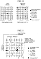
- FIG. 4 shows this "funny position" together with an integer picture position, a 1/2 picture position, and a 1/4 picture position.
- motion compensation of 1/4 pixel accuracy is realized.
- the motion vector 3 detected by the motion detection section 32 indicates an integer pixel position (the pixel position of (1 pixel, 1 pixel)) "D" in the reference frame picture 5 in relation to an integer pixel position "A" in the frame picture signal 2 to be encoded.
- a pixel value of the pixel position "D” in the reference frame picture 5 becomes a "motion compensation value” in relation to the pixel position "A” in the frame picture signal 2 to be encoded.
- the motion vector 3 indicates a 1/2 pixel position (the pixel position of (1/2 pixel, 1/2 pixel)) "E" in the reference frame picture 5 in relation to the integer pixel position "A" in the frame picture signal 2 to be encoded.
- an interpolation value obtained by independently operating 6 tap filters (1, -5, 20, 20, -5, 1)/32 vertically and horizontally for the pixel value of the integer pixel position in the reference frame picture 5 becomes a "motion compensation value" in relation to the pixel position "A" in the frame picture signal 2 to be encoded.
- the motion vector 3 indicates a 1/4 pixel position (a pixel position of (1/4 pixel, 1/4 pixel)) "F” or "G” in the reference frame picture 5 in relation to the integer pixel position "A" in the frame picture signal 2 to be encoded.
- a linear interpolation value of a pixel value of a neighboring integer pixel position and a pixel value of a neighboring 1/2 pixel position 5 becomes a "motion compensation value” in relation to the pixel position "A" in the frame picture signal 2 to be encoded.
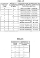
- a "motion compensation value" in relation to the integer pixel position in the frame picture signal 2 to be encoded becomes an average of a pixel value of (N, M), a pixel value of (N, M+1), a pixel value of (N+1, M) and a pixel value of (N+1, M+1) in the reference frame picture 5.
- (N+3/4 pixel, M+3/4 pixel: N and M are given integers) in the reference frame picture 5 is the aforementioned "funny position".
- a "motion compensation value” in relation to the pixel position "A” in the frame picture signal 2 to be encoded is not a value calculated in the aforementioned case of the 1/4 pixel position (e.g., the pixel position "F"), but a value obtained by calculation of (A+B+C+D)/4.
- the calculation of 1/4 picture accuracy is carried out by linear interpolation of the pixel values of the neighboring pixel positions.
- a low-pass type operation is provided in a frequency space, so as to generate a smoothed predicted picture signal 6.
- a "motion compensation value" is calculated based on an average of pixel values of 4 neighboring integer pixel positions, so as to generate a further smoothed predicted picture signal. If Gaussian noise is superimposed on the predicted picture signal, the smoothing has an effect of reducing a prediction error when this noise component is large.
- the "funny position” is defined by an absolute value of the motion vector 3.
- MVx indicates an X element of the motion vector
- MVy indicates a Y element of the motion vector.
- an object of the invention is to express a predicted picture signal with lighter overheads, and to provide motion compensation of different degrees of pixel accuracy.
- a first arrangement is summarized as a moving picture encoding device for encoding a moving picture constituted of a time sequence of frame pictures by motion compensation.
- the moving picture encoding device includes a motion vector detection section configured to detect a motion vector of a predetermined area to be encoded in the frame picture; a prediction section configured to predict the motion vector of the predetermined area to be encoded by using an encoded motion vector of a predetermined area in the frame picture; a determination section configured to determine whether or not the motion vector detected by the motion vector detection section is a predetermined motion vector set in accordance with the motion vector predicted by the prediction section; and a switching section configured to switch a method of calculating a motion compensation value for the predetermined area to be encoded depending on whether or not the motion vector detected by the motion vector detection section is the predetermined motion vector.
- a second arrangement is summarized as a moving picture decoding device for decoding a moving picture constituted of a time sequence of frame pictures by motion compensation.
- the moving picture decoding device includes a motion vector decoding section configured to decode a motion vector of a predetermined area to be decoded in the frame picture; a prediction section configured to predict the motion vector of the predetermined area to be decoded by using a decoded motion vector of a predetermined area in the frame picture; a determination section configured to determine whether or not the motion vector decoded by the motion vector decoding section is a predetermined motion vector set in accordance with the motion vector predicted by the prediction section; and a switching section configured to switch a method of calculating a motion compensation value for the predetermined area to be decoded depending on whether or not the motion vector decoded by the motion vector decoding section is the predetermined motion vector.
- a third arrangement is summarized as a moving picture encoding method for encoding a moving picture constituted of a time sequence of frame pictures by motion compensation.
- the moving picture encoding method includes a step A of detecting a motion vector of a predetermined area to be encoded in the frame picture; a step B of predicting the motion vector of the predetermined area to be encoded by using an encoded motion vector of a predetermined area in the frame picture; a step C of determining whether or not the motion vector detected in the step A is a predetermined motion vector set in accordance with the motion vector predicted in the step B; and a step D of switching a method of calculating a motion compensation value of the predetermined area to be encoded depending on whether or not the motion vector detected in the step A is the predetermined motion vector.
- a fourth arrangement is summarized as a moving picture decoding method for decoding a moving picture constituted of a time sequence of frame pictures by motion compensation.
- the moving picture decoding method includes a step A of decoding a motion vector of a predetermined area to be decoded in the frame picture; a step B of predicting the motion vector of the predetermined area to be decoded by using a decoded motion vector of a predetermined area in the frame picture; a step C of determining whether or not the motion vector decoded in the step A is a predetermined motion vector set in accordance with the motion vector predicted in the step B; and a step D of switching a method of calculating a motion compensation value of the predetermined area to be decoded depending on whether or not the motion vector decoded in the step A is the predetermined motion vector.
- a fifth arrangement is summarized as a program for causing a computer to function as a moving picture encoding device for encoding a moving picture constituted of a time sequence of frame pictures by motion compensation.
- the moving picture encoding device includes a motion vector detection section configured to detect a motion vector of a predetermined area to be encoded in the frame picture; a prediction section configured to predict the motion vector of the predetermined area to be encoded by using an encoded motion vector of a predetermined area in the frame picture; a determination section configured to determine whether or not the motion vector detected by the motion vector detection section is a predetermined motion vector set in accordance with the motion vector predicted by the prediction section; and a switching section configured to switch a method of calculating a motion compensation value of the predetermined area to be encoded depending on whether or not the motion vector detected by the motion vector detection section is the predetermined motion vector.
- a sixth arrangement is summarized as a program for causing a computer to function as a moving picture decoding device for decoding a moving picture constituted of a time sequence of frame pictures by motion compensation.
- the moving picture decoding device includes a motion vector decoding section configured to decode a motion vector of a predetermined area to be decoded in the frame picture; a prediction section configured to predict the motion vector of the predetermined area to be decoded by using a decoded motion vector of a predetermined area in the frame picture; a determination section configured to determine whether or not the motion vector decoded by the motion vector decoding section is a predetermined motion vector set in accordance with the motion vector predicted by the prediction section; and a switching section configured to switch a method of calculating a motion compensation value of the predetermined area to be decoded depending on whether nor not the motion vector decoded by the motion vector decoding section is the predetermined motion vector.
- a seventh arrangement is summarized as a computer readable recording medium which stores a program for causing a computer to function as a moving picture encoding device for encoding a moving picture constituted of a time sequence of frame pictures by motion compensation.
- the moving picture encoding device includes a motion vector detection section configured to detect a motion vector of a predetermined area to be encoded in the frame picture; a prediction section configured to predict the motion vector of the predetermined area to be encoded by using an encoded motion vector of a predetermined area in the frame picture; a determination section configured to determine whether or not the motion vector detected by the motion vector detection section is a predetermined motion vector set in accordance with the motion vector predicted by the prediction section; and a switching section configured to switch a method of calculating a motion compensation value of the predetermined area to be encoded depending on whether or not the motion vector detected by the motion vector detection section is the predetermined motion vector.
- the predetermined motion vector is preferably set to be different from the motion vector predicted by the prediction section.
- the determination section when difference information between the motion vector predicted by the prediction section and the motion vector detected by the motion vector detection section is a predetermined value, the determination section preferably determines that the motion vector detected by the motion vector detection section is the predetermined motion vector.
- An eighth arrangement is summarized as a computer readable recording medium which stores a program for causing a computer to function as a moving picture decoding device for decoding a moving picture constituted of a time sequence of frame pictures by motion compensation.
- the moving picture decoding device includes a motion vector decoding section configured to decode a motion vector of a predetermined area to be decoded in the frame picture; a prediction section configured to predict the motion vector of the predetermined area to be decoded by using a decoded motion vector of a predetermined area in the frame picture; a determination section configured to determine whether or not the motion vector decoded by the motion vector decoding section is a predetermined motion vector set in accordance with the motion vector predicted by the prediction section; and a switching section configured to switch a method of calculating a motion compensation value of the predetermined area to be decoded depending on whether nor not the motion vector decoded by the motion vector decoding section is the predetermined motion vector.
- the predetermined motion vector is preferably set to be different from the motion vector predicted by the prediction section.
- the determination section when difference information between the motion vector predicted by the prediction section and the motion vector decoded by the motion vector decoding section is a predetermined value, the determination section preferably determines that the motion vector decoded by the motion vector decoding section is the predetermined motion vector.
- a ninth arrangement is summarized as a moving picture encoding device for encoding a moving picture constituted of a time sequence of frame pictures by motion compensation.
- the moving picture encoding device includes a reference picture generation section configured to generate a plurality of different reference pictures by executing a plurality of different picture processing on a reference frame picture; a motion compensation section configured to calculate a motion compensation value for a predetermined area to be encoded by using the generated reference picture; and a transmission section configured to transmit a combination of information regarding the reference picture used for calculating the motion compensation value and information indicating the motion compensation value.
- the information regarding the reference picture is a combination of identification information of the reference frame picture and information indicating the picture processing.
- a tenth arrangement is summarized as a moving picture encoding device for encoding a moving picture constituted of a time sequence of frame pictures by motion compensation.
- the moving picture encoding device includes a reference picture generation section configured to generate a reference picture subjected to predetermined picture processing from a reference frame picture in accordance with an encoding condition of a predetermined area to be encoded; and a motion compensation section configured to calculate a motion compensation value for the predetermined area to be encoded by using the generated reference picture subjected to the predetermined picture processing.
- the moving picture decoding device includes a reference picture generation section configured to generate a plurality of different reference pictures by executing a plurality of different picture processing on a reference frame picture; a decoding section configured to decode information regarding a reference picture used for calculating a motion compensation value in a motion picture encoding device; and a motion compensation section configured to calculate a motion compensation value for a predetermined area to be decoded by using the generated reference picture specified by the information regarding the reference picture.
- the information regarding the reference picture is a combination of identification information of the reference frame picture and information indicating the picture processing.
- a twelfth arrangement is summarized as a moving picture decoding device for decoding a moving picture constituted of a time sequence of frame pictures by motion compensation.
- the moving picture decoding device includes a reference picture generation section configured to generate a reference picture subjected to predetermined picture processing from a reference frame picture in accordance with an encoding condition of a predetermined area to be decoded; and a motion compensation section configured to calculate a motion compensation value for the predetermined area to be decoded by using the reference picture subjected to the predetermined picture processing.
- a thirteenth arrangement is summarized as a moving picture encoding method for encoding a moving picture constituted of a time sequence of frame pictures by motion compensation.
- the moving picture encoding method includes a step A of generating a plurality of different reference pictures by executing a plurality of different picture processing on a reference frame picture; a step B of calculating a motion compensation value for a predetermined area to be encoded by using the generated reference picture; and a step C of transmitting a combination of information regarding the reference picture used for calculating the motion compensation value and information indicating the motion compensation value.
- the information regarding the reference picture is a combination of identification information of the reference frame picture and information indicating the picture processing.
- a fourteenth arrangement is summarized as a moving picture encoding method for encoding a moving picture constituted of a time sequence of frame pictures by motion compensation.
- the moving picture encoding method includes a step A of generating a reference picture subjected to predetermined picture processing from a reference frame picture in accordance with an encoding condition of a predetermined area to be encoded; and a step B of calculating a motion compensation value for the predetermined area to be encoded by using the generated reference picture subjected to the predetermined picture processing.
- a fifteenth arrangement is summarized as a moving picture decoding method for decoding a moving picture constituted of a time sequence of frame pictures by motion compensation.
- the moving picture decoding method includes a step A of generating a plurality of different reference pictures by executing a plurality of different picture processing on a reference frame picture; a step B of decoding information regarding a reference picture used for calculating a motion compensation value in a motion picture encoding device; and a step C of calculating a motion compensation value for a predetermined area to be decoded by using the generated reference picture specified by the information regarding the reference picture.
- the information regarding the reference picture is a combination of identification information of the reference frame picture and information indicating the picture processing.
- a sixteenth arrangement is summarized as a moving picture decoding method for decoding a moving picture constituted of a time sequence of frame pictures by motion compensation.
- the moving picture decoding method includes a step A of generating a reference picture subjected to predetermined picture processing from a reference frame picture in accordance with an encoding condition of a predetermined area to be decoded; and a step B of calculating a motion compensation value for the predetermined area to be decoded by using the generated reference picture subjected to the predetermined picture processing.
- a seventeenth arrangement is summarized as a program for causing a computer to function as a moving picture encoding device for encoding a moving picture constituted of a time sequence of frame pictures by motion compensation.
- the moving picture encoding device includes a reference picture generation section configured to generate a plurality of different reference pictures by executing a plurality of different picture processing on a reference frame picture; a motion compensation section configured to calculate a motion compensation value for a predetermined area to be encoded by using the generated reference picture; and a transmission section configured to transmit a combination of information regarding the reference picture used for calculating the motion compensation value and information indicating the motion compensation value.
- the information regarding the reference picture is a combination of identification information of the reference frame picture and information indicating the picture processing.
- An eighteenth arrangement is summarized as a program for causing a computer to function as a moving picture encoding device for encoding a moving picture constituted of a time sequence of frame pictures by motion compensation.
- the moving picture encoding device includes a reference picture generation section configured to generate a reference picture subjected to predetermined picture processing from a reference frame picture in accordance with encoding conditions of a predetermined area to be encoded; and a motion compensation section configured to calculate a motion compensation value for the predetermined area to be encoded by using the generated reference picture subjected to the predetermined picture processing.
- a nineteenth arrangement is summarized as a program for causing a computer to function as a moving picture decoding device for decoding a moving picture constituted of a time sequence of frame pictures by motion compensation.
- the moving picture decoding device includes a reference picture generation section configured to generate a plurality of different reference pictures by executing a plurality of different picture processing on a reference frame picture; a decoding section configured to decode information regarding a reference picture used for calculating a motion compensation value in a motion picture encoding device; and a motion compensation section configured to calculate a motion compensation value for a predetermined area to be decoded by using the generated reference picture specified by the information regarding the reference picture.
- the information regarding the reference picture is a combination of identification information of the reference frame picture and information indicating the picture processing.
- a twentieth arrangement is summarized as a program for causing a computer to function as a moving picture decoding device for decoding a moving picture constituted of a time sequence of frame pictures by motion compensation.
- the moving picture decoding device includes a reference picture generation section configured to generate a reference picture subjected to predetermined picture processing from a reference frame picture in accordance with an encoding condition of a predetermined area to be decoded; and a motion compensation section configured to calculate a motion compensation value for the predetermined area to be decoded by using the generated reference picture subjected to the predetermined picture processing.
- a twenty-first arrangement is summarized as a computer readable recording medium which stores a program for causing a computer to function as a moving picture encoding device for encoding a moving picture constituted of a time sequence of frame pictures by motion compensation.
- the moving picture encoding device includes a reference picture generation section configured to generate a plurality of different reference pictures by executing a plurality of different picture processing on a reference frame picture; a motion compensation section configured to calculate a motion compensation value for a predetermined area to be encoded by using the generated reference picture; and a transmission section configured to transmit a combination of information regarding the reference picture used for calculating the motion compensation value and information indicating the motion compensation value.
- the information regarding the reference picture is a combination of identification information of the reference frame picture and information indicating the picture processing.
- the motion compensation section is configured to switch the reference picture used for calculating the motion compensation value by a unit for detecting the motion vector, and that the transmission section is configured to transmit the combination of the information regarding the reference picture and the information indicating the motion compensation value by a unit for detecting the motion vector.
- the information regarding the reference picture is a combination of identification information indicating a unit for detecting the motion vector and the information indicating the picture processing, and that the transmission section is configured to transmit a combination of the information regarding the reference picture, the identification information of the reference frame picture and the information indicating the motion compensation value for each predetermined area to be encoded.
- the picture processing is a processing of changing space resolution
- the motion compensation section is configured to reduce accuracy of the motion vector used for calculating the motion vector when the reference picture of low space resolution is used.
- the information regarding the reference picture dynamically changes the combination of the identification information of the reference frame picture and the information indicating the picture processing, in accordance with an encoding condition of the predetermined area to be encoded.
- the information regarding the reference picture dynamically changes the combination of the identification information indicating the unit for detecting the motion vector and the information indicating the picture processing, in accordance with an encoding condition of the predetermined area to be encoded.
- a twenty-second arrangement is a computer readable recording medium which stores a program for causing a computer to function as a moving picture encoding device for encoding a moving picture constituted of a time sequence of frame pictures by motion compensation.
- the moving picture encoding device includes a reference picture generation section configured to generate a reference picture subjected to predetermined picture processing from a reference frame picture in accordance with an encoding condition of a predetermined area to be encoded; and a motion compensation section configured to calculate a motion compensation value for the predetermined area to be encoded by using the generated reference picture subjected to the predetermined picture processing.
- the reference picture generation section is configured to generate the reference picture subjected to the predetermined picture processing in accordance with a type of a unit for detecting a motion vector.
- the reference picture generation section is configured to generate the reference picture subjected to the predetermined picture processing in accordance with a quantization step.
- a twenty-third arrangement is a computer readable recording medium which stores a program for causing a computer to function as a moving picture decoding device for decoding a moving picture constituted of a time sequence of frame pictures by motion compensation.
- the moving picture decoding device includes a reference picture generation section configured to generate a plurality of different reference pictures by executing a plurality of different picture processing on a reference frame picture; a decoding section configured to decode information regarding a reference picture used for calculating a motion compensation value in a motion picture encoding device; and a motion compensation section configured to calculate a motion compensation value for a predetermined area to be decoded by using the generated reference picture specified by the information regarding the reference picture.
- the information regarding the reference picture is a combination of identification information of the reference frame picture and information indicating the picture processing.
- the decoding section is configured to decode information regarding the reference picture and information indicating the motion compensation value by a unit for detecting a motion vector, and that the motion compensation section is configured to switch the reference picture used for calculating the motion compensation value by the unit for detecting the motion vector.
- the information regarding the reference picture is a combination of identification information indicating a unit for detecting the motion vector and information indicating the picture processing, and that the decoding section is configured to decode the information regarding the reference picture, identification information of the reference frame picture, and information indicating the motion compensation value by a unit of the predetermined area to be decoded.
- the motion compensation section is configured to calculate a motion compensation value for the predetermined area to be decoded by using the generated reference picture specified by the information regarding the reference picture and the identification information of the reference frame picture.
- the picture processing is a processing of changing space resolution
- the motion compensation section is configured to reduce accuracy of the motion vector used for calculating the motion compensation value when the reference picture of low space resolution is used.
- the information regarding the reference picture dynamically changes the combination of the identification information of the reference frame picture and the information indicating the picture processing, in accordance with encoding conditions of the predetermined area to be decoded.
- the information regarding the reference picture dynamically changes the combination of the identification information indicating the unit for detecting the motion vector and the information indicating the picture processing, in accordance with an encoding condition of the predetermined area to be decoded.
- a twenty-fourth arrangement is a computer readable recording medium which stores a program for causing a computer to function as a moving picture decoding device for decoding a moving picture constituted of a time sequence of frame pictures by motion compensation.
- the moving picture decoding device includes a reference picture generation section configured to generate a reference picture subjected to predetermined picture processing from a reference frame picture in accordance with an encoding condition of a predetermined area to be decoded; and a motion compensation section configured to calculate a motion compensation value for the predetermined area to be decoded by using the generated reference picture subjected to the predetermined picture processing.
- the reference picture generation section is configured to generate the reference picture subjected to the predetermined picture processing, in accordance with a type of a unit for detecting a motion vector.
- the reference picture generation section is configured to generate the reference picture subjected to the predetermined picture processing, in accordance with a quantization step.
- a twenty-fifth arrangement is a moving picture encoding device for encoding a moving picture constituted of a time sequence of frame pictures by motion compensation.
- the moving picture encoding device includes a reference picture generation section configured to generate a plurality of different reference pictures by executing a plurality of different picture processing on a reference frame picture; a 3-dimensional motion vector generation section configured to generate a 3-dimensional motion vector by correlating a motion vector detected by using the reference picture with information indicating picture processing executed for the reference picture; a motion compensation section configured to calculate a motion compensation value for a predetermined area to be encoded by using the generated reference picture; and a transmission section configured to transmit a combination of the 3-dimensional motion vector and information indicating the motion compensation value.
- a twenty-sixth arrangement is a moving picture decoding device for decoding a moving picture constituted of a time sequence of frame pictures by motion compensation.
- the moving picture decoding device includes a reference picture generation section configured to generate a plurality of different reference pictures by executing a plurality of different picture processing on a reference frame picture; a decoding section configured to decode a 3-dimensional motion vector of a predetermined area to be decoded; and a motion compensation section configured to calculate a motion compensation value for the predetermined area to be decoded by using the generated reference picture specified by the 3-dimensional motion vector.
- a twenty-seventh arrangement is a moving picture encoding method for encoding a moving picture constituted of a time sequence of frame pictures by motion compensation.
- the moving picture encoding method includes a step A of generating a plurality of different reference pictures by executing a plurality of different picture processing on a reference frame picture; a step B of generating a 3-dimensional motion vector by correlating a motion vector detected by using the reference picture with information indicating picture processing executed for the reference picture; a step C of calculating a motion compensation value for a predetermined area to be encoded by using the generated reference picture; and a step D of transmitting a combination of the 3-dimensional motion vector and information indicating the motion compensation value.
- a twenty-eighth arrangement is a moving picture decoding method for decoding a moving picture constituted of a time sequence of frame pictures by motion compensation.
- the moving picture decoding method includes a step A of generating a plurality of different reference pictures by executing a plurality of different picture processing on a reference frame picture; a step B of decoding a 3-dimensional motion vector of a predetermined area to be decoded; and a step C of calculating a motion compensation value for the predetermined area to be decoded by using the generated reference picture specified by the 3-dimensional motion vector.
- a twenty-ninth arrangement is a program for causing a computer to function as a moving picture encoding device for encoding a moving picture constituted of a time sequence of frame pictures by motion compensation.
- the moving picture encoding device includes a reference picture generation section configured to generate a plurality of different reference pictures by executing a plurality of different picture processing on a reference frame picture; a 3-dimensional motion vector generation section configured to generate a 3-dimensional motion vector by correlating a motion vector detected by using the reference picture with information indicating picture processing executed for the reference picture; a motion compensation section configured to calculate a motion compensation value for a predetermined area to be encoded by using the generated reference picture; and a transmission section configured to transmit a combination of the 3-dimensional motion vector and information indicating the motion compensation value.
- a thirtieth arrangement is a program for causing a computer to function as a moving picture decoding device for decoding a moving picture constituted of a time sequence of frame pictures by motion compensation.
- the moving picture decoding device includes a reference picture generation section configured to generating a plurality of different reference pictures by executing a plurality of different picture processing on a reference frame picture; a decoding section configured to decode a 3-dimensional motion vector of a predetermined area to be decoded; and a motion compensation section configured to calculate a motion compensation value for the predetermined area to be decoded by using the generated reference picture specified by the 3-dimensional motion vector.
- a thirty-first arrangement is a computer readable recording medium which stores a program for causing a computer to function as a moving picture encoding device for encoding a moving picture constituted of a time sequence of frame pictures by motion compensation.
- the moving picture encoding device includes a reference picture generation section configured to generate a plurality of different reference pictures by executing a plurality of different picture processing on a reference frame picture; a 3-dimensional motion vector generation section configured to generate a 3-dimensional motion vector by correlating a motion vector detected by using the reference picture with information indicating picture processing executed for the reference picture; a motion compensation section configured to calculate a motion compensation value for a predetermined area to be encoded by using the generated reference picture; and a transmission section configured to transmit a combination of the 3-dimensional motion vector and information indicating the motion compensation value.
- the reference picture generation section is configured to generate the plurality of different reference pictures by executing filter processing using a filter which has a plurality of different pass bands, and that the 3-dimensional motion vector identifies the filter.
- a 3-dimensional motion vector prediction section is provided for predicting a 3-dimensional motion vector by using a correlation between an encoded predetermined area in the frame picture and the predetermined area to be encoded, and that the transmission section is configured to transmit a combination of difference information between the 3-dimensional motion vector generated by the 3-dimensional motion vector generation section and the 3-dimensional motion vector predicted by the 3-dimensional motion vector prediction section as well as the information indicating the motion compensation value.
- the 3-dimensional motion vector prediction section is configured to predict the 3-dimensional motion vector by switching a context in arithmetic encoding.
- the picture processing is a processing of changing space resolution
- the 3-dimensional motion vector generation section is configured to reduce accuracy of a 3-dimensional motion vector for a reference picture of low space resolution.
- a thirty-second arrangement is a computer readable recording medium which stores a program for causing a computer to function as a moving picture decoding device for decoding a moving picture constituted of a time sequence of frame pictures by motion compensation.
- the moving picture decoding device includes a reference picture generation section configured to generate a plurality of different reference pictures by executing a plurality of different picture processing on a reference frame picture; a decoding section configured to decode a 3-dimensional motion vector of a predetermined area to be decoded; and a motion compensation section configured to calculate a motion compensation value for the predetermined area to be decoded by using the generated reference picture specified by the 3-dimensional motion vector.
- the reference picture generation section is configured to generate the plurality of different reference pictures by executing filter processing using a filter which has a plurality of different pass bands, and that the 3-dimensional motion vector identifies the filter.
- a 3-dimensional motion vector prediction section is provided for predicting a 3-dimensional motion vector by using a correlation between a decoded predetermined area in the frame picture and the predetermined area to be decoded, and that the motion compensation section is configured to calculate a motion compensation value for the predetermined area to be decoded by using difference information between the 3-dimensional motion vector decoded by the decoding section and the 3-dimensional motion vector predicted by the 3-dimensional motion vector prediction section.
- the 3-dimensional motion vector prediction section is configured to predict the 3-dimensional motion vector by switching a context in arithmetic encoding.
- the difference in configuration of the moving picture encoding device 20 and the moving picture decoding device 50 between the embodiment of the present invention and the conventional embodiment lies in the difference in configuration of the motion compensation sections 33 and 72 between the present and conventional technology.
- the motion compensation section 33 of the moving picture encoding device 20 and the motion compensation section 72 of the moving picture decoding device 50 have the same configuration.
- the motion compensation section 33 of the moving picture encoding device 20 will be described hereinafter.
- the moving picture encoding device 20 of the embodiment is configured to encode a moving picture (an input video signal 1) constituted of a time sequence of frame pictures by motion compensation.
- the moving picture decoding device 50 of the embodiment is configured to decode a moving picture (an output video signal 1A) constituted of a time sequence of frame pictures by motion compensation.
- a motion detection section 32 constitutes a motion vector detection section configured to detect a motion vector 3 of a predetermined area (e.g., a macro-block) to be encoded in the frame picture.
- a variable length decoding section 71 constitutes a motion vector decoding section configured to decode a motion vector 3 of a predetermined area (e.g., a macro-block) to be decoded in the frame picture.
- the motion compensation section 33 of the moving picture encoding device 20 of the embodiment includes a motion vector input section 33a, a reference frame picture input section 33b, a predicted motion vector calculation section 33c, a determination section 33d, and a predicted picture signal generation section 33e.
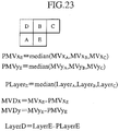
- MV B (MVx B , MVy B )
- MV C (MVx C , MVy C ) of a predetermined area in the frame picture.
- the motion vector input section 33a is connected to the determination section 33d, and is configured to receive the motion vector MV E detected by the motion detection section 32, so as to transmit the motion vector MV E to the determination section 33d.
- the reference frame picture input section 33b is connected to the predicted motion vector calculation section 33c and the determination section 33d, and is configured to extract motion vectors of neighboring areas (macro-blocks A, B and C) of the predetermined area to be encoded, which are stored in a frame memory 34, so as to transmit the vectors to the predicted motion vector calculation section 33c. Also, the reference frame picture input section 33 is configured to extract a reference frame picture 5 stored in the frame memory 34, so as to transmit the reference frame picture 5 to the determination section 33d.
- PMVx E indicates a horizontal element (an X element) of a predicted motion vector
- PMVy E indicates a vertical element (a Y element) of the predicted motion vector
- a motion vector of a predetermined area to be encoded is predicted and encoded by a prediction system called “median prediction” through using an encoded motion vector of a neighboring area included in the reference frame picture 5.
- a predicted motion vector PMV is set as a zero vector.
- a value of a predicted motion vector PMV E of the predetermined area (the macro-block) E to be encoded is always obtained, by using an assumption that the motion vectors of the neighboring areas (the macro-blocks) A, B and C are set to zero vectors or other assumptions.
- MVDx which is an X element of the difference information is calculated by "MVx E -PMVx E”
- MVDy which is a Y element of the difference information MVD is calculated by "MVy E -PMVy E ".
- the motion vector MV is encoded in a form of the aforementioned difference information MVD so as to be transmitted.
- the determination section 33d is connected to the motion vector input section 33a, the reference frame picture input section 33b, the predicted motion vector calculation section 33c and the predicted picture signal generation section 33e.
- the determination section 33d is configured to determine a method of generating a predicted picture signal 6 (a method for calculating a motion compensation value), so as to put the method to the predicted picture signal generation section 33e, in accordance with the motion vector MV E from the motion vector input section 33a and the predicted motion vector PMV E from the predicted motion vector calculation section 33c.
- the determination section 33d determines whether or not the motion vector MV E indicates a "funny position" in accordance with a phase of the vertical component PMVy E of the predicted motion vector generated by the predicted picture signal generation section 33e and the motion vector MV E detected by the motion detection section 32, and puts a result of the determination to the predicted picture signal generation section 33e.
- a unit regarding expression of the predicted motion vector PMV E and the motion vector MV E is a 1/4 pixel.
- the determination section 33d determines that the motion vector MV E (MVx E , MVy E ) of the predetermined area (the macro-block E) to be encoded indicates a "funny position".
- the determination section 33d determines that the motion vector MV E (MVx E , MVy E ) of the predetermined area (the macro-block E) to be encoded indicates the "funny position.”
- an area indicated by the predicted motion vector PMV E is adjusted so as not to be superimposed on the "funny position". That is, the predicted motion vector PMV E predicted by the predicted motion vector calculation section 33c (the prediction section) is set to be different from the motion vector (the predetermined motion vector) indicating the "funny position".
- the motion compensation of the conventional "H. 26L encoding system" is applied as it is (i.e., the motion vector indicating a pixel position a (see FIG. 7 ) indicates the "funny position").
- a motion vector indicating a different pixel position b (see FIG. 7 ) is supposed to indicate the "funny position".
- an obtained "motion compensation value” is smoothed as an average of pixel values of 4 neighboring integer pixel positions which surround the motion vector, and other motion compensation processing is similar to the motion compensation processing of the conventional "H. 26L encoding system".
- the predicted picture signal generation section 33e is connected to the determination section 33d, and is configured to generate a predicted picture signal 6, by switching the "generation method of a predicted picture signal 6" regarding the predetermined area (the macro-block) to be encoded.
- the predicted picture signal generation section 33e smoothes the predicted picture signal 6 of the predetermined area as an average of pixel values of the 4 neighboring integer pixel positions which surround the pixel position indicated by the motion vector MV E , and generates the predicted picture signal 6 of the predetermined area by the conventional "H. 26L encoding system" in other cases.
- the motion compensation section 33 and the motion detection section 32 are separately disposed.
- the motion compensation section 33 and the motion detection section 32 may be integrally disposed.
- FIG. 8 shows operation of the aforementioned motion compensation section 33.
- the predicted motion vector calculation section 33c calculates a predicted motion vector PMV E which is a predicted value of a motion vector of a predetermined area (a macro-block E in FIG. 5 ) to be encoded in a frame picture, based on encoded motion vectors MV A , MV B and MV C of neighboring areas (the macro-blocks A, B and C in FIG. 5 ) in the same frame picture.
- the determination section 33d determines whether or not a motion vector MV E indicates a "funny position", in accordance with a phase of a vertical element PMVy E of the predicted motion vector from the predicted motion vector calculation section 33c and the motion vector MV E from the motion vector input section 33a.
- step 403 when the aforementioned motion vector MV E indicates the "funny position", the predicted picture signal generation section 33e generates a predicted picture signal 6 of the predetermined area in a smoothed form.
- step 404 when the aforementioned motion vector MV E does not indicate the "funny position", the predicted picture signal generation section 33e generates a predicted picture signal 6 of the predetermined area by the conventional "H. 26L encoding system".
- step 501 the variable length decoding section 71 detects a "synchronous word" which indicates a head of a picture (each frame picture constituting an input video signal 1).
- the variable length decoding section 71 decodes a "picture header" of the aforementioned picture.
- the "picture header” contains "picture type information” for determining whether the picture is a "picture which encodes all the macro-blocks constituting the picture by an INTRA prediction mode (hereinafter referred to as "I picture")” or a “picture which uses an INTER prediction mode (hereinafter referred to as a "P picture”).”
- the picture header contains a value of a quantization parameter in an orthogonal transformation coefficient and the like.
- step 503 the variable length decoding section 71 decodes a "RUN" in the macro-block layer.
- the "RUN” indicates the number of repeated macro-blocks in which data of the macro-block layer is zero, and macro-blocks (skip MBs) to which as many skip modes as the number of the "RUN" are applied are generated.
- step 504 it is determined whether or not a macro-block to be decoded is a skip MB.
- step 505 an area of 16 ⁇ 16 pixels in the same position on a predetermined reference frame picture 5 stored in the frame memory 73 is employed, as it is, for a predicted picture signal 6.
- This processing is carried out by transmitting a motion vector whose value is zero and an identification number of the predetermined reference frame picture to the motion compensation section 72 by the variable length decoding section 71.
- step 506 it is determined whether or not the "RUN" of the MB indicates the last MB of the picture.
- step 507 the variable length decoding of the picture is terminated, and a variable length decoding of a next picture begins.
- step 508 the variable length decoding section 71 decodes a "MB_Type (a macro-block type).
- MB_Type a prediction mode 4 of the predetermined area (the macro-block) to be decoded is established.
- step 509 it is determined whether or not the established prediction mode 4 is an "INTER prediction mode".
- step 510 the variable length decoding section 71 decodes an "intra_pred_mode”.
- step 511 the space prediction section 74 executes space prediction from a pixel value of a neighboring area based on the "intra_pred_mode", so as to generate a predicted picture signal 7.
- the prediction mode 4 is the "INTER prediction mode"
- the prediction mode 4 is one of the modes 1 to 7 shown in FIG. 3 .
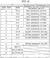
- the numbers of "Ref_frames (reference frame picture numbers)” and “MVDs (difference information of motion vector)" to be decoded are established.
- the variable length decoding section 71 decodes a combination of the "Ref_frame” and the "MVD”.
- step 512 it is determined whether or not the "Ref_frame” is present in accordance with a value of the "picture type information".
- variable length decoding section 71 decodes the "Ref_frame”, and then, in step 514, the variable length decoding section 71 decodes the "MVD”. If the "Ref_frame” is not present, only the "MVD” is decoded in step 514.
- step 514 based on the prediction mode 4 established by the "Ref_frame", the "MVD” and the "MB_Type” which have been obtained, motion vectors MV corresponding to all the 4x4 blocks in the MB are restored.
- step 515 the motion compensation section 72 generates a predicted picture signal 6 for each of 4x4 blocks based on the "Rev_frame” and the motion vector MV. Processing regarding the "funny position" is reflected here.
- step 516 the variable length decoding section 71 restores a quantized orthogonal transformation coefficient 11.
- step 517 the inverse quantization section 76 restores the orthogonal transformation coefficient 10.
- step 518 the inverse orthogonal transformation section 77 resotres a predicted residual signal 9.
- step 519 at the adder 78, a predicted picture signal 8 from the switch 75 and the predicted residual signal 9 from the inverse orthogonal transformation section 77 are summed up to obtain a frame picture signal 2 of the MB. Then, the process proceeds to the decoding of a next MB.
- the predicted picture signal generation section 33e switches the method of calculating a motion compensation value for the predetermined area to be encoded, in accordance with the determination result of the determination section 33d, i.e., the predicted motion vector predicted by the predicted motion vector calculation section 33c. For this reason, it is possible to express a pixel value of the same pixel position (N+3/4 pixel, M+3/4 pixel: N and M are given integers) as the "funny position".
- the method of generating a predicted picture signal or a motion compensation value described in the embodiment is merely an example.
- a given generation method necessary for realizing the switching of the calculation method of the motion compensation value executed according to the embodiment can be used.
- modification is introduced in the motion compensation section 33 of the moving picture encoding device 20 and the motion compensation section 72 of the moving picture decoding device 50 of the foregoing embodiment.
- the motion compensation section 33 of the moving picture encoding device 20 and the motion compensation section 72 of the moving picture decoding section 50 are identical.
- the motion compensation section 33 of the moving picture encoding device 20 will be described.
- the determination section 33d determines that the motion vector MV E (MVx E , MVy E ) indicates a "funny position".
- an area indicated by the predicted motion vector PMV E is adjusted so as not to be superimposed on the "funny position". That is, the motion vector indicating the "funny position" is set to be different from the predicted motion vector PMV E .
- the modified example 1A has an effect of reducing a possibility of superimposition of the motion vector which becomes a "funny position" on real motion, by using the predicted encoding structure of the motion vector.
- the motion compensation section 33 of the moving picture encoding device 20 and the motion compensation section 72 of the moving picture decoding device 50 of the foregoing embodiment are changed.
- the motion compensation section 33 of the moving picture encoding device 20 and the motion compensation section 72 of the moving picture decoding section 50 are identical.
- the motion compensation section 33 of the moving picture encoding device 20 will be described.
- the determination section 33d constitutes a determination section configured to determine that the motion vector MV E detected by the motion vector detection section (the motion detection section 32) is a predetermined motion vector (a motion vector indicating the "funny position"), when difference information MVD E between a motion vector PMV E predicted by the prediction section (the predicted motion vector calculation section 33c) and the motion vector MV E detected by the motion vector detection section (the motion detection section 32) is equal to a predetermined value.
- a unit regarding expression of the motion vector MV E (MVx E , MVy E ) is a 1/4 pixel.
- the determination section 33d determines that the motion vector MV E (MVx E , MVy E ) detected by the motion detection section 32 indicates a "funny position".
- the motion compensation is carried out based on the average of the pixel values of the integer pixel positions which surround the "funny position".
- the "funny position" itself is represented as an integer pixel position, and an integer pixel position for obtaining an average may not be established.
- a motion compensation operation is carried out as follows.
- the motion vector MV E (MVx E , MVy E ) indicates an integer pixel position "D”.
- the predicted picture generation section 33e causes a motion compensation value of a predetermined area (a macro-block or sub-block) to take on an average of a pixel value of (MVX E +2, MVy E +2), a pixel value of (MVx E +2, MVy E -2), a pixel value of (MVx E -2, MVy E +2) and a pixel value of (MVx E -2, MVy E -2) in the reference frame picture 5.
- a motion compensation value of a predetermined area a macro-block or sub-block
- the predicted picture generation section 33e may obtain a motion compensation value of the predetermined area (the macro-block or sub-block) to be encoded, exclusively from a pixel value of an integer pixel position in the reference frame picture 5.
- the motion compensation value is caused to take on an average of a pixel value of ((MVx E /4) ⁇ 4, (MVy E /4) ⁇ 4), a pixel value of (((MVx E +4)/4) ⁇ 4, (MVy E /4) ⁇ 4), a pixel value of (((MVx E /4) ⁇ 4, ((MVy E +4)/4) ⁇ 4) and a pixel value of (((MVx E +4)/4) ⁇ 4, ((MVy E +4)/4) ⁇ 4).
- Embodiment 1 has been referred to countermeasures against the problem regarding the transmission of the motion vector MV (or difference information MVD of the motion vector) which indicates the "funny position", i.e., the problem of the obstructed transmission of a real motion vector MV.
- the real motion vector MV can not be transmitted.
- the moving picture encoding and decoding devices can carry out motion compensation from reference pictures whose degrees of smoothness are different from one predetermined area to be encoded to another, by separately preparing a predicted picture signal which is strongly smoothed like provided by the "motion compensation value" in the "funny position" of the Embodiment 1 and a predicted picture signal of a normal "motion compensation value” in a position other than the "funny position", and by signaling identification information of these 2 kinds of predicted picture signals together with a reference frame picture number.
- the motion compensation can be carried out without using the "funny position".
- FIG. 12 is a schematic view of the moving picture encoding device 20 of the embodiment
- FIG. 13 is a schematic view of the moving picture decoding device 50.
- Embodiment 2 operations are similar to those of the moving picture encoding device 20 and the moving picture decoding device 50 described in the "TML-8", except that the motion compensation is executed from a different reference picture without using "funny positions". Thus, details thereof are omitted, and description will focus on differences.
- the reference picture generation sections 45 and 80 are configured to generate a plurality of different reference pictures (normal first reference pictures or second reference pictures of strong smoothing application) 17, by executing a plurality of different picture processing on a reference frame picture 5.
- a plurality of different reference pictures normal first reference pictures or second reference pictures of strong smoothing application
- processing for changing degrees of smoothness processing for changing degrees of space resolution, and the like are conceived.
- picture processing a case of using processing for changing a degree of smoothness will be described.
- the motion compensation section 33 is configured to calculate a motion compensation value (a predicted picture signal 6) for a predetermined area (a macro-block) to be encoded, by using the reference picture 17 in place of the reference frame picture 5.
- variable length encoding section 40 constitutes a transmission section configured to transmit a combination of "information (a reference frame code: Ref_frame) regarding the reference picture 17" used for calculating the motion compensation value (the predicted picture signal 6) and "information (a predicted residual signal data encoding syntax: Texture Coding Syntax) indicating the motion compensation value".
- variable length decoding section 71 constitutes a decoding section configured to decode the "information (the Ref_frame) regarding the reference picture" used for calculating the motion compensation value in the moving picture encoding device 20, and the "information (the predicted residual signal data encoding syntax) indicating the motion compensation value".
- variable length decoding section 71 transmits a motion vector 3, a prediction mode 4, and a "reference frame code (an Ref_frame)" 4A, to the motion compensation 72.
- the motion compensation section 72 is configured to calculate a motion compensation value for a predetermined area (a macro-block) to be encoded, by using the reference picture 17 specified by the "information (the Ref_frame) regarding the reference picture" in place of the reference frame picture 5.
- the "information (the reference frame code: Ref_frame) regarding the reference picture 17" is a combination of "identification information (a reference frame picture number) of the reference frame picture” and "information (a first reference picture or second reference picture) indicating a degree of smoothness”.
- the reference picture generation section 45 generates a normal reference picture (hereinafter, referred to as a first reference picture) which has no "funny position".
- a "motion compensation value" of the first reference picture is equal to a "motion compensation value” in each pixel position of an integer pixel position, a 1/2 pixel position and a 1/4 pixel position of the "TML-8", except that an original "motion compensation value” is used even for a "motion compensation value" in the same position as the "funny position" of the TML-8".
- the "motion compensation value" of the first reference picture in the same pixel position as the "funny position” of the "TML-8" is generated as an average of four points of pixel values of a neighboring integer pixel position and a neighboring 1/2 pixel position as in the case of the "motion compensation value” in a position (1/4 pixel, 1/4 pixel) other than the "funny position" of the "TML-8".
- a reference picture (hereinafter, referred to as a second reference picture) which is strongly smoothed like provided by the "motion compensation value" in the "funny position" of the "TML-8" is generated by using the first reference picture.
- the second reference picture can be generated by executing picture processing with various kinds of smoothing filers for each pixel value of the first reference picture.
- the second reference picture having 1/4 pixel accuracy can be generated by independently operating 3 tap filters (1, 4, 1)/6 having smoothing effects vertically and horizontally for the pixel value of each pixel position of the first reference picture having 1/4 pixel accuracy.
- a plurality of encoded frame pictures which differ from one another with time are prepared as reference frame pictures 5, and these can be used as reference pictures for motion compensation. Additionally, bits of identification information of these encoded frame pictures which differ from one another with time are discriminated as reference frame picture numbers.
- identification information of the first reference picture or identification information of the second reference picture i.e., information of a method of generating a reference picture and the reference frame picture number are combined to be transmitted.
- the reference picture generation sections 45 and 80 generate a first and a second reference pictures whose degrees of smoothness are different. Consequently, these reference frame pictures can be used as "reference pictures" for motion compensation in the motion compensation sections 33 and 72.
- FIG. 14 shows an "encoding syntax for each macro-block unit according to the H. 26L encoding system" used in the embodiment. According to the embodiment, there is no variation from the encoding syntax for each macro-block unit of the H. 26L encoding system. However, definition of an "Ref_frame” is changed to a combination of a “reference frame picture number” and “identification information of a method of generating a reference picture", i.e., a "reference frame code”.
- encoding can be carried out without containing information regarding a plurality of "MB_TYPEs", "Ref_frames” and the like.
- the encoding syntax it is possible to repeatedly transmit difference information MVD of a motion vector and a predicted residual signal data encoding syntax (a Texture Coding Syntax), in response to an act of transmitting a "MB_TYPE", a "Ref_frame” or the like.
- the predicted residual signal data encoding syntax is obtained by subjecting a quantized orthogonal transformation coefficient 11 to variable length encoding.
- FIG. 15 shows an example of a reference frame code (an Ref_frame) based on a combination of a reference frame picture number and identification information of a generation method of a reference picture.
- the second reference picture is more strongly smoothed than the first reference picture which is a normal reference picture, and the second reference picture is a reference picture which does not have space resolution that an original picture (a reference frame picture 5) has.
- the second reference picture is used, only when encoding distortion is suppressed more when a reference picture of a stronger degree of smoothness is used and motion compensation efficiency is improved. Thus, it is less likely that the second reference picture is chosen, compared with the first reference picture.
- the first reference picture which is a normal reference picture is chosen as a reference picture used for motion compensation.
- a reference frame code table for defining reference frame codes to be transmitted in this case is similar to that for defining reference frame codes (Ref_frames)" of the "H. 26L encoding system” shown in FIG. 16 .
- Ref_frames reference frame codes
- the moving picture encoding device 20 of the present invention by using two kinds of reference pictures of different degrees of smoothness, i.e., a normal reference picture (a first reference picture) formed by the reference picture generation section 45 and a reference picture (a second reference picture) of a strong degree of smoothness, it is possible to carry out motion compensation using a reference picture of a degree of smoothness different from one predetermined area (e.g., a macro-block) to be encoded to another.
- a normal reference picture a first reference picture
- a second reference picture a reference picture of a strong degree of smoothness
- a degree of smoothness for the reference picture can be signaled by generating a reference frame code through combining the "identification information of the method of generating the reference picture” with the "reference frame picture number”. Accordingly, it is possible to solve the problem that strong smoothing is always applied to the "motion compensation value" in the area having a motion vector which indicates the same pixel position as the "funny position" as in the case of the "H. 26L encoding system".
- the filter of the present embodiment for generating the second reference picture which is a reference picture of a strong degree of smoothness is only an example. By applying a filter for processing other than smoothing, it is possible to realize prediction based on a reference picture of a different nature.
- the maximum number of reference frame pictures used for reference picture generation is "5".
- the present invention is not limited to this number, and a maximum number of reference frame pictures can be optionally set.
- the maximum number of reference frame pictures used for reference picture generation is given as known in the moving picture encoding device 20 and the moving picture decoding device 50.
- the maximum number of reference frame pictures may be decided by such a method or based on information of the compressed stream 12 sent from the moving picture encoding device 20 to the moving picture decoding device 50.
- the maximum number of reference frame pictures used for reference picture generation is uniquely determined in the moving picture encoding device 20 and the moving picture decoding device 50.
- a reference frame code table can be uniquely determined in accordance with the maximum number of reference frame pictures used for reference picture generation.
- a "reference frame code (an Ref_frame)" which is a combination of the “reference frame picture number” and the “second reference picture” is allocated after a “reference frame code (an Ref_frame)” which is a combination of the "reference frame picture number” and the "first reference picture”.
- an Ref_frame reference frame code
- those of smaller reference frame picture numbers among second reference pictures of strong degrees of smoothness can be arranged higher in place on the reference frame code table.
- the reference frame code table may be determined uniquely in accordance with the encoding conditions of the predetermined area (the macro-block) to be encoded as described above. Or the reference frame code may be changed dynamically in accordance with the aforementioned encoding conditions.
- a prediction mode i.e., kind of a unit for detecting the motion vector
- the quantization step the QP value
- the kind of the unit for detecting the motion vector for example, a size of a sub-block for detecting the motion vector and the like is conceived.
- the second reference picture of a strong degree of smoothness may be frequently used, when low bit rate encoding is applied. Accordingly, if the quantization step is equal to or lower than a predetermined threshold value, the "reference frame code" containing the "second reference picture” is arranged lower on the reference frame code table. If the quantization step exceeds the predetermined threshold value, some “reference codes” containing "second reference pictures” are arranged upper on the reference frame code table.
- the "reference frame code table" for defining the “reference frame code” which is a combination of the “reference frame picture number” and the “identification information of the method of generating the reference picture” shown in FIG. 15 is only an example. It is possible to use an given reference frame code table necessary for realizing switching, to be executed according to the embodiment, between the "reference frame picture number” and the “identification information of the method of generating the reference picture”.
- the degree of smoothness of the reference picture may be automatically switched to be uniquely determined in accordance with the encoding conditions of the predetermined area (the macro-block) to be encoded, in place of the explicit signaling of the degree of smoothness of the reference picture used for the motion compensation by using the reference frame code (the Ref_frame).
- the reference picture generation section 45 may generate a reference picture 17 of a predetermined degree of smoothness, in accordance with the encoding conditions (units for detecting the motion vector, quantization steps and the like) of the predetermined area (the macro-block) to be encoded.
- complex motion may occur in an area encoded by a "macro-block mode (an MB_Type: a prediction mode)" in which the predetermined area (the macro-block) to be encoded is finely divided, and accordingly the reference picture used for motion compensation may not need high pixel value accuracy.
- a macro-block mode an MB_Type: a prediction mode
- the reference picture used of motion compensation may not need high pixel value accuracy.
- the second reference picture of a strong degree of smoothness may always be used.
- the reference pictures (first and second reference pictures) 17 of two different kinds of generation methods are formed. Subsequently, the formed “identification information (information indicating a degree of smoothness) of the method of generating the reference picture” and “the reference frame picture number (identification information of the reference frame picture)" are combined to generate the "reference frame code (the information regarding the reference picture)".
- the motion compensation can be carried out by using the reference picture whose degree of smoothness is changed from one predetermined area (a macro-block) to be encoded to another.
- the switching of degrees of smoothness has been possible only by the macro-block unit which is a unit for allocating the reference frame picture number.
- a moving picture encoding device 20 and a moving picture decoding device 50 which can transmit a combination of "reference frame code” and a “sub-block unit (a unit for detecting a motion vector)".
- the "reference frame code” is generated by combining a reference frame picture number with identification information of a method of generating a reference picture.
- the sub-block is part of a macro-block in which the motion compensation is executed.
- a motion compensation section 33 switches reference pictures (a first reference picture or a second reference picture) 17 used for calculating a motion compensation value by a unit (a sub-block unit) for detecting a motion vector.
- a variable length encoding section 40 transmits a combination of "information regarding reference pictures (Ref_frames)" and "information indicating motion compensation value (a predicted residual signal data encoding syntax)" by a unit (a sub-block unit) for detecting a motion vector.
- variable length decoding section 71 decodes "information regarding reference pictures (reference frame codes)" and "information indicating motion compensation value (a predicted residual signal data encoding syntax)" by a unit (a sub-block unit) for detecting a motion vector.
- a motion compensation section 72 switches the reference pictures 17 used for calculating the motion compensation value by a unit (a sub-block unit) for detecting a motion vector.
- FIG. 17 shows an encoding syntax based on a macro-block unit according to the modified example.
- the number of "reference frame codes (Ref_frames)" can be notified by a "macro-block type (an MB_type)", because a type and the number of a sub-block are transmitted by the "macro-block type (the MB_type)".
- a macro-block type is an "INTER prediction mode (a mode 7)
- the number of “reference frame codes (Ref_frames)" to be transmitted is "16".
- the "sub-block" unit which is a unit for detecting a motion vector in the macro-block, it is possible to carry out motion compensation by using the reference picture 17 of a different degree of smoothness.
- motion compensation which uses a reference frame picture 5 different from sub-block to sub-block. Accordingly, motion compensation of a higher degree of freedom can be carried out in response to a shape and motion of a frame picture signal 2.
- the degree of smoothness of the reference picture may be automatically switched to be uniquely determined in accordance with the encoding conditions of the predetermined area (a macro-block or a sub-block) for detecting a motion vector, in place of the explicit signaling of the degree of smoothness of the reference picture used for the motion compensation by using the reference frame code (the Ref_frame).
- the Modified Example 2 of the Embodiment 2 will be described. Except for motion compensation executed by using a different reference picture 17 without using a "funny position", operations of the moving picture encoding device 20 and the moving picture decoding device 50 according to the present embodiment are similar to those of the moving picture encoding device 20 and the moving picture decoding device 50 described in the "TML-8". Thus, details thereof are omitted, and description will focus on differences.
- the reference pictures (first and second reference pictures) of two different kinds of generation methods (degrees of smoothness) are formed. Subsequently, the formed “identification information of the generation method of the reference picture” and “the reference frame picture number” are combined to generate the "reference frame code".
- the motion compensation in which degrees of smoothness is changed from one predetermined area e.g., a macro-block: a unit for allocating a reference frame picture number
- one predetermined area e.g., a macro-block: a unit for allocating a reference frame picture number
- two kinds of reference pictures (first and second reference pictures) of different degrees of smoothness are formed, and the formed "identification information of the generation method of the reference picture” and a "macro-block mode” are combined to generate a "macro-block mode code".
- information regarding a reference picture is a combination of "identification information indicating a unit for detecting a motion vector (a macro-block mode: MB_Type)" and "information indicating a degree of smoothness (a first reference picture or second reference picture)".
- a variable length encoding section 40 transmits a combination of "information regarding reference picture (macro-block mode codes)", “identification information of reference frame pictures (a reference frame picture number: an Ref_frame)” and “information indicating motion compensation value (a predicted residual signal data encoding syntax)", by a unit of a predetermined area (a macro-block unit) to be encoded.
- variable length decoding section 71 decodes "information regarding reference pictures (macro-block mode codes: MB_Types)", “identification information of reference frame pictures (a reference frame picture number: an Ref_frame)” and "an information predicted residual signal data encoding syntax indicating motion compensation value", by a unit of a predetermined area (a macro-block) to be encoded.
- a motion compensation section 72 uses a reference picture 17 specified by "information regarding a reference picture (an MB_Type)" and "identification information of a reference frame picture (an Ref_frame)" in place of a reference frame picture 5, so as to calculate a motion compensation value for the predetermined area (the macro-block) to be encoded.
- FIG. 14 shows an encoding syntax based on a macro-block unit according to the H. 26L encoding system.
- definition of a "macro-block mode" (an MB_Type)" is changed to be expressed by a combination of a "macro-block mode” and "identification method of a generation method of a reference picture".
- FIG. 18 shows an example of a "macro-block mode code (an MB_type)" based on a combination of a “macro-block mode” and "identification information of a method of generating a reference picture".
- the macro-block mode is allocated to a macro-block unit, it is possible to carry out motion compensation from a reference picture of a different degree of smoothness by a macro-block unit.
- the degree of smoothness of the reference picture may be automatically switched to be uniquely determined in accordance with the encoding conditions of an area (a macro-block) to be encoded, in place of the explicit signaling of the degree of smoothness of the reference picture used for the motion compensation by using the macro-block mode code (the MB_Type).
- the Modified Example 2C of the foregoing Embodiment 2 will be described.
- the second reference picture of the forgoing Embodiment 2 is subjected to strong smoothing, and a motion vector of the same accuracy as that of the first reference picture is not always necessary in motion compensation.
- description will be made of a configuration in which accuracy of a motion vector is changed when the second reference picture is used.
- differences between the modified example and the foregoing embodiment 2 will be described.
- a motion compensation section 33 when a reference picture (a second reference picture) of a strong degree of smoothness is used, a motion compensation section 33 reduces accuracy of a motion vector used for calculating a motion compensation value (a predicted picture signal 6). Specifically, in such a case, the motion compensation section 33 is configured to reduce accuracy of horizontal and vertical elements of the motion vector.
- a reference picture generation section 45 generates a reference picture subjected to strong smoothing as a second reference picture in which space resolution is reduced to 1/2 pixel accuracy or integer pixel accuracy, after generating a first reference picture.
- // represents integer division which accompanies a rounding operation in a zero direction.
- a strongly smoothed reference picture whose space resolution is reduced to integer pixel accuracy is generated as a second reference picture
- the following substitution is carried out in a motion vector of the second reference picture assuming that a motion vector of a first reference picture is (MVx, MVy).
- // represents integer division which accompanies a rounding operation in a zero direction.
- a motion vector (e.g., (2, 2)) in which a generated encoding amount is small may be sent as a representative.
- difference information MVD between a predicted motion vector PMV and a motion vector may be calculated by using a motion vector after substitution is executed in accordance with space resolution, and a value of the difference information of the motion vector to be sent may be reduced. In other words, an encoding amount may be reduced.
- the modified example is characterized in that in the second reference picture of low space resolution, the space resolution of the motion vector is reduced, and redundancy at the time of motion vector encoding is avoided.
- the space resolution of the reference picture may be automatically switched to be uniquely determined in accordance with the encoding conditions of an area (a macro-block) to be encoded, in place of the explicit signaling of the space resolution of the reference picture used for the motion compensation by using the reference frame code (the Ref_frame).
- the reference picture used for motion compensation may not need high pixel value accuracy.
- a second reference picture of strong smoothing i.e., low space resolution
- the degree of smoothness and the space resolution can be automatically switched to be uniquely determined in accordance with the aforementioned encoding conditions (macro-block modes, quantization steps or the like).
- an encoding amount of the generated motion vector is reduced, by reducing space resolution to 1/2 pixel accuracy or integer pixel accuracy, by always utilizing a reference picture which uses a filer to apply a strong degree of smoothness, and by decreasing pixel accuracy of horizontal and vertical elements of the motion vector.
- the moving picture encoding and decoding devices enable motion compensation to be executed by using the normal reference picture (the first picture information) and the strongly smoothed reference picture (the second picture information) for each predetermined area (the macro-block) to be encoded, by signaling the "information regarding a reference picture (the reference frame code or macro-block mode code)" which is a combination of the "identification information of a method of generating the reference picture (the first reference picture or second reference picture)" and the "reference frame picture number".
- FIG. 19 shows a schematic configuration of the moving picture encoding device 20 of the embodiment
- FIG. 20 shows a schematic configuration of the moving picture decoding device 50.
- each of the hierarchical reference picture generation sections 46 and 81 constitutes a reference picture generation section configured to generate a plurality of different reference pictures (hierarchical reference pictures 18), by executing a plurality of different picture processing on a reference frame picture 15.
- a reference picture generation section configured to generate a plurality of different reference pictures (hierarchical reference pictures 18), by executing a plurality of different picture processing on a reference frame picture 15.
- processing for changing degrees of smoothness, processing for changing space resolution, and the like are conceived. Description of the embodiment will refer to the processing for changing the space resolution is used as the aforementioned picture processing.
- each of the hierarchical reference picture generation sections 46 and 81 generates a reference picture (a hierarchical reference picture 18) having a plurality of space resolutions by executing filtering through a filter which has a plurality of different pass bands.
- a reference picture a hierarchical reference picture 18
- information indicating picture processing i.e., information indicating space resolution (layer)
- layer is an identifier of the filter.
- the motion detection section 32 constitutes a 3-dimensional motion vector generation section configured to generate a "3-dimensional motion vector (Layer, MVx, MVy)" by correlating a "motion vector (MVx, MVy)" detected by using the reference picture (the hierarchical reference picture 18) with "information indicating space resolution of the reference picture (the hierarchical reference picture 18) (Layer)".
- the motion detection section 32 may be configured to reduce accuracy of the 3-dimensional motion vector for a reference picture of low space resolution (e.g., a layer 3 or the like).
- the motion compensation section 33 (72) is configured to calculate a motion compensation value for a predetermined area (a macro-block) to be encoded (decoded), by using the reference picture (the hierarchical reference picture 18) in place of the reference frame picture 5.
- the motion compensation section 33 constitutes a 3-dimensional motion vector prediction section configured to predict a 3-dimensional motion vector, by using a correlation (e.g., a switching of a context in arithmetic encoding) between an encoded predetermined area (an encoded macro-block) in a frame picture and the predetermined area to be encoded (the macro-block to be encoded).
- a correlation e.g., a switching of a context in arithmetic encoding
- variable length encoding section 40 constitutes a transmission section configured to transmit a combination of the "3-dimensional motion vector" and "information indicating a motion compensation value”.
- variable length encoding section 40 may transmit a combination of difference information (Layer D, MVDx, MVDy) between the 3-dimensional motion vector (Layer, MVx, MVy) generated by the motion detection section 32 and a 3-dimensional motion vector (Player, PMVx, PMVy) predicted by the motion compensation section 33, and information indicating a motion compensation value.
- variable length decoding section 71 constitutes a decoding section configured to decode a 3-dimensional motion vector of a predetermined area to be decoded.
- Each of the hierarchical reference picture generation sections 46 and 81 generates 3 layers for the reference frame picture 5 used for the motion compensation by each of the motion compensation sections 33 and 72.
- each of the hierarchical reference picture generation sections 46 and 81 subjects the reference frame picture 5 to up-sampling by 8 tap filers, so as to generate a layer 1 of 1/4 pixel accuracy which is one of hierarchical reference pictures 18.
- 8 tap filters used here are as follows:
- a pixel value of an integer pixel position a pixel value of the same position of the reference frame picture 5 is copied. Pixel values of the 1/4 pixel position, the 2/4 pixel position and the 3/4 pixel position between integer pixel positions are found by multiplication and summation of the aforementioned filter coefficients for the pixel value of the integer pixel position. This filter processing is carried out separately in horizontal and vertical directions.
- the filtering processing is described in an up-sampling operation of 1/8 pixel accuracy of the conventional "TML-8", and thus details thereof are omitted.
- each of the hierarchical reference picture generation sections 46 and 81 subjects the generated layer 1 of 1/4 pixel accuracy to down-sampling by 3 tap filters (low pass band type filters), so as to generate a layer 2 of 1/2 pixel accuracy which is one of hierarchical reference pictures 18.
- 3 tap filters low pass band type filters
- An example of the 3 tap filters used here is "(1, 2, 1)/4.”
- each of the hierarchical reference picture generation sections 46 and 81 subjects the generated layer 2 of 1/2 pixel accuracy to down-sampling by the 3 tap filters, so as to generate a layer 3 of integer pixel accuracy which is one of hierarchical reference pictures 18.
- the 3 tap filers used here are the same as those which have been previously used.
- the layer 1 has 1/4 pixel accuracy as in the case of the conventional technology, but a pixel value of the 1/4 pixel position is calculated not by linear interpolation but by executing the aforementioned filter processing so as to maintain space resolution of an original picture (an reference frame picture 5).
- each of the hierarchical reference picture generation sections 46 and 81 generates reference pictures (layer 1 to layer 3) having a plurality of space resolutions through filter processing by the filter having the plurality of different bass bands.
- the motion compensation section 33 executes motion compensation by using the hierarchical reference picture 18 generated in the foregoing manner.
- a motion vector 3 is not a group of 2 terms (a 2-dimensional motion vector) of (MVx, MVy) but a group of 3 terms (a 3-dimensional motion vector) of (Layer, MVx, MVy).
- the motion detection section 32 detects the 3-dimensional motion vector (Layer, MVx, MVy) in place of the 2-dimensional motion vector (MVx, MVy).
- the layer 2 has space resolution half of that of the layer 1, and further the layer 3 has space resolution half of that of the layer 2. Thus, the following substitution is carried out.
- // represents integer division accompanied by a rounding operation in a zero direction.
- the layers 2 and 3 have a plurality of values (MVx, MVy) for the same motion vector.
- (2, 3, 3), (2, 2, 3), (2, 2, 3) and (2, 2, 2) indicate the same motion vector.
- a motion vector of a small amount of encoding (e.g., (2, 2, 2) in the aforementioned case) may be sent as a representative.
- difference information MVD between a predicted motion vector PMV and a motion vector may be calculated by using the motion vector after substitution in accordance with space resolution of each layer, and a value of the difference information MVD of the motion vector to be sent may be reduced. That is, an amount of encoding may be reduced.
- the predicted motion vector calculation section 33c of the motion compensation section 22 predicts a 3-dimensional motion vector expanded to a plurality of space resolutions, by a method that is virtually the same as that of the foregoing Embodiment 1.
- a "PMVx E” denotes a horizontal element of a predicted motion vector PMV E for a predetermined area (a macro-block) E to be encoded
- a "PMVy E” denotes a vertical element of the predicted motion vector PMV E for the predetermined area (the macro-block) E to be encoded.
- a "Player E" indicates predicted space resolution of the predicted area (the macro-block) E to be encoded.
- Each of the "MVDx E " and the “MVDy E” indicates difference information of a motion vector of 1/4 pixel accuracy for the predetermined area (the macro-block) E to be encoded.
- a “LayerD” indicates difference information of space resolution for the predetermined area (the macro-block) E to be encoded.
- encoding processing is carried out for a group of 3 terms of (LayerD, MVDx, MVDy).
- the motion compensation section 33 may predict a 3-dimensional motion vector of a predetermined area (a macro-block) to be encoded, by using the 3-dimensional motion vector of the encoded predetermined area (the macro-block) in the frame picture signal 2, calculate difference information between the predicted 3-dimensional motion vector and the 3-dimensional motion vector detected by the motion vector detection section 32, and execute motion compensation by using the calculated difference information of the 3-dimensional motion vector.
- adaptive arithmetic encoding realized in the conventional technology may be used, and further expansion in which 3 states of a context model of Player are added may be executed so as to use a correlation with a macro-block of a neighboring area.
- the predicted difference encoding which uses the Player and the LayerD is carried out.
- the execution of the predicted difference encoding is identical to execution of context modeling.
- the present invention has referred to the new motion compensation in which the "2-dimensional motion vector" is expanded as the "3-dimensional motion vector" which contains the "information (Layer) indicating the picture processing (space resolution)", instead of transmitting the "2-dimensional motion vector" and the "information indicating picture processing (information indicating space resolution)".
- step 1201 the hierarchical reference picture generation section 46 generates a hierarchical reference picture 18 by using a reference frame picture 5 extracted from the frame memory 34.
- step 1202 the motion detection section 32 detects a 3-dimensional motion vector of a predetermined area (a macro-block) to be encoded, by referring to the hierarchical reference picture 18 from the hierarchical reference picture generation section 46.
- step 1203 the motion compensation section 33 generates a predicted picture signal 6 based on the 3-dimensional motion vector from the motion detection section 32 and the hierarchical reference picture 18 from the hierarchical reference picture generation section 46.
- the layer picture (e.g., layer 2 or 3) of low space resolution is characterized in that space resolution of the 3-dimensional motion vector is reduced, and in that redundancy during encoding of the 3-dimensional motion vector is avoided.
- the 3-dimensional vector is employed.
- a vector distribution on parameter space of the 3-dimensional motion vector is expected to be continuous spatially, and efficiency improvement of encoding can be expected.
- the method of generating the predicted picture signal or the motion compensation value according to the present embodiment is only an example. It is possible to use an optional generation method necessary for realizing the switching of a calculation method of a motion compensation value executed in the present embodiment.
- the motion detection section 32 since the motion detection section 32 generates a 3-dimensional motion vector in accordance with the hierarchical reference picture 17, it is possible to carry out motion compensation of pixel accuracy different from one predetermined area to be encoded to another.
- the modified example is different from the foregoing Embodiment 3 in that motion compensation is executed not by 1/4 pixel accuracy, but by 1/2 pixel accuracy.
- each of the hierarchical reference picture generation section 46 and 81 executes up-sampling by applying 6 tap filters (1, -5, 20, 20, -5, 1)/32" used in the conventional "TML-8" to the reference frame picture 5, so as to generate a layer 1 of 1/2 pixel accuracy.
- the modified example is different from the foregoing Embodiment 3 in that each of the hierarchical reference picture generation section 46 and 81 independently applies a smoothing filter "(1, 2, 1)/4" to the layer 1 horizontally/vertically, so as to generate a layer 2.
- the modified example is different from the foregoing Embodiment 3 in that the number of layers is 2 (layer 1 and layer 2), and in that both has the same space resolution.
- the 3-dimensional motion vector of (LayerD, MVDx, MVDy) is encoded.
- "Adaptive arithmetic encoding” is different from that of the foregoing Embodiment 3 in that a context of PlayerE takes two states.
- the filter "(1, 2, 1)/4" for generating the layer 2 picture is a simple low pass type filter.
- a smoothing filter of an edge holding type may be used.
- smoothing filters of the edge holding type are a “median filter” • for obtaining an intermediate value of an area of 3 pixels ⁇ 3 pixels, and a “dynamic weighting filter” described in US patent 6,041,145 "Device and method for smoothing picture signal, device and method for encoding picture and device and method for decoding picture” can be used.
- the aforementioned "dynamic weighting filter” is what executes adaptive smoothing by calculating a difference absolute value between a smoothed center pixel value and its neighboring pixel value, and by providing a filter coefficient inversely proportional to the difference absolute value to a peripheral pixel value (near 8).
- a program for causing a computer 100 to function as the moving picture encoding device 20 or the moving picture decoding device 50 of the present invention can be stored in a computer readable recording medium.
- a floppy disk 101, a compact disk 102, an IC chip 103, a cassette tape 104 or the like can be listed. According to such a computer readable recording medium which stores the program, the aforementioned program can be easily saved, transported, sold or the like.
Claims (14)
- Dispositif de codage d'image animée (20) pour coder une image animée constituée d'une séquence temporelle d'images de trame par compensation de mouvement, le dispositif comprenant :une section de détection de vecteur de mouvement (32) configurée pour détecter un vecteur de mouvement d'une zone prédéterminée à coder dans l'image de trame ;une section de prédiction (33c) configurée pour prédire le vecteur de mouvement de la zone prédéterminée à coder, en utilisant un vecteur de mouvement codé d'une zone prédéterminée dans l'image de trame ;une section de détermination (33d) configurée pour fixer un vecteur de mouvement prédéterminé indiquant une position de pixel prédéterminée sur la base du vecteur de mouvement prédit par la section de prédiction, et configurée pour déterminer si oui ou non le vecteur de mouvement détecté par la section de détection de vecteur de mouvement indique la position de pixel prédéterminée; dans lequel la section de détermination (33d) est configurée pour fixer le vecteur de mouvement prédéterminé pour indiquer soit une position de pixel de (N+3/4, M+3/4) soit une position de pixel de (N+1/4, M+1/4), selon que le vecteur de mouvement prédit par la section de prédiction où une phase d'une composante verticale PMVyE du vecteur de mouvement prédit est PMVyE%4 soit égal à 0 ou 1, ou soit égal à 2 ou 3, N et M étant exprimés en entiers donnés; etune section de commutation (33e) configurée pour commuter à un procédé de calcul d'une valeur de compensation de mouvement de la zone prédéterminée à coder en tant que moyenne de valeurs de pixel de positions de pixel entier voisines qui entourent la position de pixel indiquée par le vecteur de mouvement détecté par la section de détection de vecteur de mouvement, si le vecteur de mouvement détecté par la section de détection de vecteur de mouvement indique la position de pixel prédéterminée, dans lequelle vecteur de mouvement prédéterminé est fixé pour être différent du vecteur de mouvement prédit par la section de prédiction.
- Dispositif de codage d'image animée selon la revendication 1, dans lequel la section de détermination (33d) est configurée pour déterminer que le vecteur de mouvement détecté par la section de détection de vecteur de mouvement (32) est le vecteur de mouvement prédéterminé, quand des informations de différence entre le vecteur de mouvement prédit par la section de prédiction et le vecteur de mouvement détecté par la section de détection de vecteur de mouvement sont une valeur prédéterminée.
- Dispositif de décodage d'image animée (50) pour décoder une image animée constituée d'une séquence temporelle d'images de trame par compensation de mouvement, le dispositif comprenant :une section de décodage de vecteur de mouvement (71) configurée pour décoder un vecteur de mouvement d'une zone prédéterminée à décoder dans l'image de trame ;une section de prédiction (33c) configurée pour prédire le vecteur de mouvement de la zone prédéterminée à décoder, en utilisant un vecteur de mouvement décodé d'une zone prédéterminée dans l'image de trame ;une section de détermination (33d) configurée pour fixer un vecteur de mouvement prédéterminé indiquant une position de pixel prédéterminée sur la base du vecteur de mouvement prédit par la section de prédiction, et configurée pour déterminer si oui ou non le vecteur de mouvement décodé par la section de décodage de vecteur de mouvement indique la position de pixel prédéterminée; dans lequel la section de détermination (33d) est configurée pour fixer le vecteur de mouvement prédéterminé pour indiquer soit une position de pixel de (N+3/4, M+3/4) soit une position de pixel de (N+1/4, M+1/4), selon que le vecteur de mouvement prédit par la section de prédiction où une phase d'une composante verticale PMVyE du vecteur de mouvement prédit est PMVyE%4 soit égal à 0 ou 1, ou soit égal à 2 ou 3, N et M étant exprimés en entiers donnés; etune section de commutation (33e) configurée pour commuter à un procédé de calcul d'une valeur de compensation de mouvement de la zone prédéterminée à décoder en tant que moyenne de valeurs de pixel de positions de pixel entier voisines qui entourent la position de pixel indiquée par le vecteur de mouvement décodé par la section de décodage de vecteur de mouvement, si le vecteur de mouvement décodé par la section de décodage de vecteur de mouvement indique la position de pixel prédéterminée, dans lequelle vecteur de mouvement prédéterminé est fixé pour être différent du vecteur de mouvement prédit par la section de prédiction.
- Dispositif de décodage d'image animée (50) selon la revendication 3, dans lequel la section de détermination (33d) est configurée pour déterminer que le vecteur de mouvement décodé par la section de décodage de vecteur de mouvement (71) est le vecteur de mouvement prédéterminé, quand des informations de différence entre le vecteur de mouvement prédit par la section de prédiction et le vecteur de mouvement décodé par la section de décodage de vecteur de mouvement sont une valeur prédéterminée.
- Procédé de codage d'image animée pour coder une image animée constituée d'une séquence temporelle d'images de trame par compensation de mouvement, le procédé comprenant :une étape A de détection d'un vecteur de mouvement d'une zone prédéterminée à coder dans l'image de trame ;une étape B de prédiction du vecteur de mouvement de la zone prédéterminée à coder, en utilisant un vecteur de mouvement codé d'une zone prédéterminée dans l'image de trame;une étape de fixation d'un vecteur de mouvement prédéterminé indiquant une position de pixel prédéterminée sur la base du vecteur de mouvement prédit par la prédiction ; dans lequel le vecteur de mouvement prédéterminé est fixé pour indiquer soit une position de pixel de (N+3/4, M+3/4) soit une position de pixel de (N+1/4, M+1/4), selon que le vecteur de mouvement prédit par la section de prédiction où une phase d'une composante verticale PMVyE du vecteur de mouvement prédit est PMVyE%4 soit égal à 0 ou 1, ou soit égal à 2 ou 3, N et M étant exprimés en entiers donnés ;une étape C de détermination si oui ou non le vecteur de mouvement détecté dans l'étape A indique la position de pixel prédéterminée ; etune étape D de commutation à un procédé de calcul d'une valeur de compensation de mouvement de la zone prédéterminée à coder en tant que moyenne de valeurs de pixel de positions de pixel entier voisines qui entourent la position de pixel indiquée par le vecteur de mouvement détecté dans l'étape A, si le vecteur de mouvement détecté dans l'étape A indique la position de pixel prédéterminée,dans lequel le vecteur de mouvement prédéterminé est fixé pour être différent du vecteur de mouvement prédit dans l'étape B.
- Procédé de codage d'image animée selon la revendication 5, dans lequel, dans l'étape C, il est déterminé que le vecteur de mouvement détecté dans l'étape A est le vecteur de mouvement prédéterminé, quand des informations de différence entre le vecteur de mouvement prédit dans l'étape B et le vecteur de mouvement détecté dans l'étape A sont une valeur prédéterminée.
- Procédé de décodage d'image animée pour décoder une image animée constituée d'une séquence temporelle d'images de trame par compensation de mouvement, le procédé comprenant :une étape A de décodage d'un vecteur de mouvement d'une zone prédéterminée à décoder dans l'image de trame ;une étape B de prédiction du vecteur de mouvement de la zone prédéterminée à décoder, en utilisant un vecteur de mouvement décodé d'une zone prédéterminée dans l'image de trame;une étape de fixation d'un vecteur de mouvement prédéterminé indiquant une position de pixel prédéterminée sur la base du vecteur de mouvement prédit par la prédiction ; dans lequel le vecteur de mouvement prédéterminé est fixé pour indiquer soit une position de pixel de (N+3/4, M+3/4) soit une position de pixel de (N+1/4, M+1/4), selon que le vecteur de mouvement prédit par la prévision où une phase d'une composante verticale PMVyE du vecteur de mouvement prédit est PMVyE%4 soit égal à 0 ou 1, ou soit égale à 2 ou 3, N et M étant exprimés en entiers donnés ;une étape C de détermination si oui ou non le vecteur de mouvement décodé dans l'étape A indique la position de pixel prédéterminée ; etune étape D de commutation à un procédé de calcul d'une valeur de compensation de mouvement de la zone prédéterminée à décoder en tant que moyenne de valeurs de pixel de positions de pixel entier voisines qui entourent la position de pixel indiquée par le vecteur de mouvement décodé dans l'étape A, selon que oui ou non le vecteur de mouvement décodé dans l'étape A indique la position de pixel prédéterminée,dans lequel le vecteur de mouvement prédéterminé est fixé pour être différent du vecteur de mouvement prédit dans l'étape B.
- Procédé de décodage d'image animée selon la revendication 7, dans lequel, dans l'étape C, il est déterminé que le vecteur de mouvement décodé dans l'étape A est le vecteur de mouvement prédéterminé, quand des informations de différence entre le vecteur de mouvement prédit dans l'étape B et le vecteur de mouvement décodé dans l'étape A sont une valeur prédéterminée.
- Programme pour amener un ordinateur à fonctionner comme un dispositif de codage d'image animée (20) pour coder une image animée constituée d'une séquence temporelle d'images de trame par compensation de mouvement, le dispositif de codage d'image animée comprenant :une section de détection de vecteur de mouvement (32) configurée pour détecter un vecteur de mouvement d'une zone prédéterminée à coder dans l'image de trame ;une section de prédiction (33c) configurée pour prédire le vecteur de mouvement de la zone prédéterminée à coder, en utilisant un vecteur de mouvement codé d'une zone prédéterminée dans l'image de trame ;une section de détermination (33d) configurée pour fixer un vecteur de mouvement prédéterminé indiquant une position de pixel prédéterminée sur la base du vecteur de mouvement prédit par la section de prédiction, et configurée pour déterminer si oui ou non le vecteur de mouvement détecté par la section de détection de vecteur de mouvement indique la position de pixel prédéterminée; dans lequel la section de détermination (33d) est configurée pour fixer le vecteur de mouvement prédéterminé pour indiquer soit une position de pixel de (N+3/4, M+3/4) soit une position de pixel de (N+1/4, M+1/4), selon que le vecteur de mouvement prédit par la section de prédiction où une phase d'une composante verticale PMVyE du vecteur de mouvement prédit est PMVyE%4 soit égal à 0 ou 1, ou soit égal à 2 ou 3, N et M étant exprimés en entiers donnés; etune section de commutation (33e) configurée pour commuter à un procédé de calcul d'une valeur de compensation de mouvement de la zone prédéterminée à coder en tant que moyenne de valeurs de pixel de positions de pixel entier voisines qui entourent la position de pixel indiquée par le vecteur de mouvement détecté par la section de détection de vecteur de mouvement, si le vecteur de mouvement détecté par la section de détection de vecteur de mouvement indique la position de pixel prédéterminée,dans lequel le vecteur de mouvement prédéterminé est fixé pour être différent du vecteur de mouvement prédit par la section de prédiction.
- Programme selon la revendication 9, dans lequel la section de détermination (33d) est configurée pour déterminer que le vecteur de mouvement détecté par la section de détection de vecteur de mouvement (32) est le vecteur de mouvement prédéterminé, quand des informations de différence entre le vecteur de mouvement prédit par la section de prédiction (33c) et le vecteur de mouvement détecté par la section de détection de vecteur de mouvement sont une valeur prédéterminée.
- Programme pour amener un ordinateur à fonctionner comme un dispositif de décodage d'image animée (50) pour décoder une image animée constituée d'une séquence temporelle d'images de trame par compensation de mouvement, le dispositif décodage d'image animée comprenant :une section de décodage de vecteur de mouvement (71) configurée pour décoder un vecteur de mouvement d'une zone prédéterminée à décoder dans l'image de trame ;une section de prédiction (33c) configurée pour prédire le vecteur de mouvement de la zone prédéterminée à décoder, en utilisant un vecteur de mouvement décodé d'une zone prédéterminée dans l'image de trame;une section de détermination (33d) configurée pour fixer un vecteur de mouvement prédéterminé indiquant une position de pixel prédéterminée sur la base du vecteur de mouvement prédit par la section de prédiction, et configurée pour déterminer si oui ou non le vecteur de mouvement décodé par la section de décodage de vecteur de mouvement indique la position de pixel prédéterminée ; dans lequel la section de détermination (33d) est configurée pour fixer le vecteur de mouvement prédéterminé pour indiquer soit une position de pixel de (N+3/4, M+3/4) soit une position de pixel de (N+1/4, M+1/4), selon que le vecteur de mouvement prédit par la section de prédiction où une phase d'une composante verticale PMVyE du vecteur de mouvement prédit est PMVyE%4 soit égal à 0 ou 1, ou soit égal à 2 ou 3, N et M étant exprimés en entiers donnés ; etune section de commutation (33e) configurée pour commuter à un procédé de calcul d'une valeur de compensation de mouvement de la zone prédéterminée à décoder en tant que moyenne de valeurs de pixel de positions de pixel entier voisines qui entourent la position de pixel indiquée par le vecteur de mouvement décodé par la section de décodage de vecteur de mouvement, si le vecteur de mouvement décodé par la section de décodage de vecteur de mouvement indique la position de pixel prédéterminée,dans lequel le vecteur de mouvement prédéterminé est fixé pour être différent du vecteur de mouvement prédit par la section de prédiction.
- Programme selon la revendication 11, dans lequel la section de détermination (33d) est configurée pour décider que le vecteur de mouvement décodé par la section de décodage de vecteur de mouvement (71) est le vecteur de mouvement prédéterminé, quand des informations de différence entre le vecteur de mouvement prédit par la section de prédiction (33c) et le vecteur de mouvement décodé par la section de décodage de vecteur de mouvement (71) sont une valeur prédéterminée.
- Support d'enregistrement lisible par ordinateur qui stocke un programme pour amener un ordinateur à fonctionner comme un dispositif de codage d'image animée (20) pour coder une image animée constituée d'une séquence temporelle d'images de trame par compensation de mouvement, le dispositif de codage d'image animée comprenant :une section de détection de vecteur de mouvement (32) configurée pour détecter un vecteur de mouvement d'une zone prédéterminée à coder dans l'image de trame;une section de prédiction (33c) configurée pour prédire le vecteur de mouvement de la zone prédéterminée à coder, en utilisant un vecteur de mouvement codé d'une zone prédéterminée dans l'image de trame;une section de détermination (33d) configurée pour fixer un vecteur de mouvement prédéterminé indiquant une position de pixel prédéterminée sur la base du vecteur de mouvement prédit par la section de prédiction, et configurée pour déterminer si oui ou non le vecteur de mouvement détecté par la section de détection de vecteur de mouvement indique la position de pixel prédéterminée; dans lequel la section de détermination (33d) est configurée pour fixer le vecteur de mouvement prédéterminé pour indiquer soit une position de pixel de (N+3/4, M+3/4) soit une position de pixel de (N+1/4, M+1/4), selon que le vecteur de mouvement prédit par la section de prédiction où une phase d'une composante verticale PMVyE du vecteur de mouvement prédit est PMVyE4 soit égal à 0 ou 1, ou soit égal à 2 ou 3, N et M étant exprimés en entiers donnés; etune section de commutation (33e) configurée pour commuter à un procédé de calcul d'une valeur de compensation de mouvement de la zone prédéterminée à coder en tant que moyenne de valeurs de pixel de positions de pixel entier voisines qui entourent la position de pixel indiquée par le vecteur de mouvement détecté par la section de détection de vecteur de mouvement, si le vecteur de mouvement détecté par la section de détection de vecteur de mouvement indique la position de pixel prédéterminée; dans lequelle vecteur de mouvement prédéterminé est fixé pour être différent du vecteur de mouvement prédit par la section de prédiction.
- Support d'enregistrement lisible par ordinateur qui stocke un programme pour amener un ordinateur à fonctionner comme un dispositif de décodage d'image animée (50) pour décoder une image animée constituée d'une séquence temporelle d'images de trame par compensation de mouvement, le dispositif de décodage d'image animée comprenant :une section de décodage de vecteur de mouvement (71) configurée pour décoder un vecteur de mouvement d'une zone prédéterminée à décoder dans l'image de trame ;une section de prédiction (33c) configurée pour prédire le vecteur de mouvement de la zone prédéterminée à décoder, en utilisant un vecteur de mouvement décodé d'une zone prédéterminée dans l'image de trame ;une section de détermination (33d) configurée pour fixer un vecteur de mouvement prédéterminé indiquant une position de pixel prédéterminée sur la base du vecteur de mouvement prédit par la section de prédiction, et configurée pour déterminer si oui ou non le vecteur de mouvement décodé par la section de décodage de vecteur de mouvement indique la position de pixel prédéterminée ; dans lequel la section de détermination (33d) est configurée pour fixer le vecteur de mouvement prédéterminé pour indiquer soit une position de pixel de (N+3/4, M+3/4) soit une position de pixel de (N+1/4, M+1/4), selon que le vecteur de mouvement prédit par la section de prédiction où une phase d'une composante verticale PMVyE du vecteur de mouvement prédit est PMVyE%4 soit égal à 0 ou 1, ou soit égal à 2 ou 3, N et M étant exprimés en entiers donnés ; etune section de commutation (33e) configurée pour commuter à un procédé de calcul d'une valeur de compensation de mouvement de la zone prédéterminée à décoder comme une moyenne de valeurs de pixel de positions de pixel entier voisines qui entourent la position de pixel indiquée par le vecteur de mouvement décodé par la section de décodage de vecteur de mouvement, si le vecteur de mouvement décodé par la section de décodage de vecteur de mouvement indique la position de pixel prédéterminée ; dans lequelle vecteur de mouvement prédéterminé est fixé pour être différent du vecteur de mouvement prédit par la section de prédiction.
Priority Applications (2)
| Application Number | Priority Date | Filing Date | Title |
|---|---|---|---|
| EP11153669.4A EP2373035B1 (fr) | 2001-11-30 | 2002-11-29 | Dispositif de codage d'images en mouvement, dispositif de décodage d'images en mouvement, procédé de codage d'images en mouvement, procédé de décodage d'images en mouvement, programme et support de stockage lisible par un ordinateur stockant le programme |
| EP20110153668 EP2339854A3 (fr) | 2001-11-30 | 2002-11-29 | Dispositif de codage d'images en mouvement, dispositif de décodage d'images en mouvement, procédé de codage d'images en mouvement, procédé de décodage d'images en mouvement, programme et support de stockage lisible par un ordinateur stockant le programme |
Applications Claiming Priority (5)
| Application Number | Priority Date | Filing Date | Title |
|---|---|---|---|
| JP2001367940 | 2001-11-30 | ||
| JP2001367940 | 2001-11-30 | ||
| JP2002129434 | 2002-04-30 | ||
| JP2002129434 | 2002-04-30 | ||
| PCT/JP2002/012556 WO2003047270A1 (fr) | 2001-11-30 | 2002-11-29 | Appareil de codage d'images mobiles, appareil de decodage d'images mobiles, procede de codage d'images mobiles, procede de decodage d'images mobiles, programme et support lisible par ordinateur contenant le programme |
Related Child Applications (3)
| Application Number | Title | Priority Date | Filing Date |
|---|---|---|---|
| EP11153669.4A Division EP2373035B1 (fr) | 2001-11-30 | 2002-11-29 | Dispositif de codage d'images en mouvement, dispositif de décodage d'images en mouvement, procédé de codage d'images en mouvement, procédé de décodage d'images en mouvement, programme et support de stockage lisible par un ordinateur stockant le programme |
| EP11153669.4A Division-Into EP2373035B1 (fr) | 2001-11-30 | 2002-11-29 | Dispositif de codage d'images en mouvement, dispositif de décodage d'images en mouvement, procédé de codage d'images en mouvement, procédé de décodage d'images en mouvement, programme et support de stockage lisible par un ordinateur stockant le programme |
| EP20110153668 Division-Into EP2339854A3 (fr) | 2001-11-30 | 2002-11-29 | Dispositif de codage d'images en mouvement, dispositif de décodage d'images en mouvement, procédé de codage d'images en mouvement, procédé de décodage d'images en mouvement, programme et support de stockage lisible par un ordinateur stockant le programme |
Publications (3)
| Publication Number | Publication Date |
|---|---|
| EP1465432A1 EP1465432A1 (fr) | 2004-10-06 |
| EP1465432A4 EP1465432A4 (fr) | 2010-03-03 |
| EP1465432B1 true EP1465432B1 (fr) | 2017-01-04 |
Family
ID=26624824
Family Applications (3)
| Application Number | Title | Priority Date | Filing Date |
|---|---|---|---|
| EP02783711.1A Expired - Fee Related EP1465432B1 (fr) | 2001-11-30 | 2002-11-29 | Appareil de codage d'images mobiles, appareil de decodage d'images mobiles, procede de codage d'images mobiles, procede de decodage d'images mobiles, programme et support lisible par ordinateur contenant le programme |
| EP20110153668 Ceased EP2339854A3 (fr) | 2001-11-30 | 2002-11-29 | Dispositif de codage d'images en mouvement, dispositif de décodage d'images en mouvement, procédé de codage d'images en mouvement, procédé de décodage d'images en mouvement, programme et support de stockage lisible par un ordinateur stockant le programme |
| EP11153669.4A Expired - Fee Related EP2373035B1 (fr) | 2001-11-30 | 2002-11-29 | Dispositif de codage d'images en mouvement, dispositif de décodage d'images en mouvement, procédé de codage d'images en mouvement, procédé de décodage d'images en mouvement, programme et support de stockage lisible par un ordinateur stockant le programme |
Family Applications After (2)
| Application Number | Title | Priority Date | Filing Date |
|---|---|---|---|
| EP20110153668 Ceased EP2339854A3 (fr) | 2001-11-30 | 2002-11-29 | Dispositif de codage d'images en mouvement, dispositif de décodage d'images en mouvement, procédé de codage d'images en mouvement, procédé de décodage d'images en mouvement, programme et support de stockage lisible par un ordinateur stockant le programme |
| EP11153669.4A Expired - Fee Related EP2373035B1 (fr) | 2001-11-30 | 2002-11-29 | Dispositif de codage d'images en mouvement, dispositif de décodage d'images en mouvement, procédé de codage d'images en mouvement, procédé de décodage d'images en mouvement, programme et support de stockage lisible par un ordinateur stockant le programme |
Country Status (5)
| Country | Link |
|---|---|
| US (5) | US8243803B2 (fr) |
| EP (3) | EP1465432B1 (fr) |
| JP (5) | JP3936335B2 (fr) |
| CN (1) | CN1316830C (fr) |
| WO (1) | WO2003047270A1 (fr) |
Families Citing this family (38)
| Publication number | Priority date | Publication date | Assignee | Title |
|---|---|---|---|---|
| KR100522595B1 (ko) * | 2002-11-29 | 2005-10-19 | 삼성전자주식회사 | 엠펙 비디오 복호화방법 및 엠펙 비디오 복호화기 |
| CN100594730C (zh) * | 2003-06-25 | 2010-03-17 | 汤姆森许可贸易公司 | 帧间的快速模式确定编码方法及其装置 |
| FR2867328A1 (fr) * | 2004-03-02 | 2005-09-09 | Thomson Licensing Sa | Procede de decodage d'une sequence d'images codee avec echelonnabilite spatiale et temporelle |
| EP1617672A1 (fr) * | 2004-07-13 | 2006-01-18 | Matsushita Electric Industrial Co., Ltd. | Estimateur/compensateur de mouvement comportant un 16-bit 1/8 pel filtre d'interpolation |
| US7609765B2 (en) | 2004-12-02 | 2009-10-27 | Intel Corporation | Fast multi-frame motion estimation with adaptive search strategies |
| US7933336B2 (en) * | 2004-11-30 | 2011-04-26 | Humax Co., Ltd. | Image down-sampling transcoding method and device |
| CN101345420B (zh) * | 2005-06-01 | 2011-03-02 | 三洋电机株式会社 | 请求控制装置以及消耗功率预测方法与程序 |
| CN101218829A (zh) * | 2005-07-05 | 2008-07-09 | 株式会社Ntt都科摩 | 动态图像编码装置、动态图像编码方法、动态图像编码程序、动态图像解码装置、动态图像解码方法以及动态图像解码程序 |
| US7965898B2 (en) * | 2005-10-28 | 2011-06-21 | Nvidia Corporation | Accelerating video decoding using multiple processors |
| JP4775132B2 (ja) * | 2006-06-20 | 2011-09-21 | ソニー株式会社 | 画像理装置および方法、プログラム、並びに記録媒体 |
| US7953285B2 (en) * | 2006-11-03 | 2011-05-31 | Taiwan Imagingtek Corporation | Method and circuit of high performance variable length coding and decoding for image compression |
| KR101086434B1 (ko) * | 2007-03-28 | 2011-11-25 | 삼성전자주식회사 | 비디오 데이터 디스플레이 방법 및 장치 |
| KR101366241B1 (ko) * | 2007-03-28 | 2014-02-21 | 삼성전자주식회사 | 영상 부호화, 복호화 방법 및 장치 |
| JP2009055542A (ja) * | 2007-08-29 | 2009-03-12 | Toshiba Corp | 動画像符号化装置および動画像符号化方法 |
| KR101365444B1 (ko) * | 2007-11-19 | 2014-02-21 | 삼성전자주식회사 | 영상의 해상도의 조정을 통하여 동영상을 효율적으로부호화/복호화하는 방법 및 장치 |
| KR101560182B1 (ko) * | 2008-01-07 | 2015-10-15 | 삼성전자주식회사 | 다시점 비디오 부호화 방법과 그 장치 및 다시점 비디오 복호화 방법과 그 장치 |
| US8804831B2 (en) * | 2008-04-10 | 2014-08-12 | Qualcomm Incorporated | Offsets at sub-pixel resolution |
| US9967590B2 (en) | 2008-04-10 | 2018-05-08 | Qualcomm Incorporated | Rate-distortion defined interpolation for video coding based on fixed filter or adaptive filter |
| FR2931610B1 (fr) * | 2008-05-20 | 2010-12-17 | Canon Kk | Procede et un dispositif de transmission de donnees d'images |
| JP2012054618A (ja) * | 2008-11-26 | 2012-03-15 | Hitachi Ltd | 動画像符号化装置及び符号化方法、動画像復号化装置及び復号化方法 |
| JP5000012B2 (ja) * | 2009-04-06 | 2012-08-15 | 三菱電機株式会社 | 動画像符号化装置、動画像復号装置、動画像符号化方法及び動画像復号方法 |
| ES2739475T3 (es) | 2009-05-11 | 2020-01-31 | Ntt Docomo Inc | Dispositivo, método y programa de codificación de imágenes en movimiento, y dispositivo, método y programa de decodificación de imágenes en movimiento |
| KR101792041B1 (ko) * | 2009-10-14 | 2017-11-02 | 톰슨 라이센싱 | 움직임 정보의 적응적 코딩 방법 및 장치 |
| JP2013514718A (ja) * | 2009-12-17 | 2013-04-25 | テレフオンアクチーボラゲット エル エム エリクソン(パブル) | 映像符号化の方法及び装置 |
| WO2011128259A1 (fr) * | 2010-04-13 | 2011-10-20 | Fraunhofer-Gesellschaft zur Förderung der angewandten Forschung e.V. | Décodeur vidéo et codeur vidéo utilisant une prévision à compensation de mouvement |
| EP2574056A4 (fr) * | 2010-05-19 | 2016-03-30 | Sk Telecom Co Ltd | Dispositif et procédé de codage/décodage d'image |
| US8787459B2 (en) * | 2010-11-09 | 2014-07-22 | Sony Computer Entertainment Inc. | Video coding methods and apparatus |
| SI3595303T1 (sl) * | 2010-11-25 | 2022-01-31 | Lg Electronics Inc. | Postopek za dekodiranje informacije o sliki, naprava za dekodiranje, postopek za kodiranje informacije o sliki, naprava za kodiranje in pomnilniški medij |
| US11284081B2 (en) | 2010-11-25 | 2022-03-22 | Lg Electronics Inc. | Method for signaling image information, and method for decoding image information using same |
| US9288501B2 (en) * | 2011-03-08 | 2016-03-15 | Qualcomm Incorporated | Motion vector predictors (MVPs) for bi-predictive inter mode in video coding |
| US10264276B2 (en) | 2011-06-14 | 2019-04-16 | Samsung Electronics Co., Ltd. | Method and apparatus for encoding motion information and method and apparatus for decoding same |
| KR20130050149A (ko) | 2011-11-07 | 2013-05-15 | 오수미 | 인터 모드에서의 예측 블록 생성 방법 |
| WO2014077651A1 (fr) * | 2012-11-19 | 2014-05-22 | 엘지전자 주식회사 | Appareil de transmission et de réception de signal, et procédé de transmission et de réception de signal |
| CN104717510B (zh) | 2013-12-13 | 2018-08-17 | 华为技术有限公司 | 用于图像处理的方法和装置 |
| JP6727902B2 (ja) * | 2016-04-22 | 2020-07-22 | 日本放送協会 | 参照フレーム生成装置、動き推定装置、及びプログラム |
| US10681354B2 (en) * | 2016-12-05 | 2020-06-09 | Lg Electronics Inc. | Image encoding/decoding method and apparatus therefor |
| US20200186795A1 (en) * | 2018-12-07 | 2020-06-11 | Beijing Dajia Internet Information Technology Co., Ltd. | Video coding using multi-resolution reference picture management |
| CN115914228B (zh) * | 2022-11-18 | 2024-02-23 | 腾讯科技(深圳)有限公司 | 一种数据处理方法、装置、存储介质及计算机程序产品 |
Family Cites Families (47)
| Publication number | Priority date | Publication date | Assignee | Title |
|---|---|---|---|---|
| JPS5885684A (ja) | 1981-11-18 | 1983-05-23 | Nec Corp | テレビジヨン信号の予測符号化装置 |
| JPH03127580A (ja) * | 1989-10-13 | 1991-05-30 | Matsushita Electric Ind Co Ltd | 動き補償フレーム間符号化装置 |
| JPH04127689A (ja) | 1990-09-19 | 1992-04-28 | Hitachi Ltd | 動画像予測符号化方式 |
| JPH04268892A (ja) | 1991-02-22 | 1992-09-24 | Mitsubishi Electric Corp | フレーム間適応予測符号化方式 |
| JPH05130592A (ja) | 1991-10-31 | 1993-05-25 | Toshiba Corp | 動画像符号化装置 |
| JP2925046B2 (ja) | 1991-10-31 | 1999-07-26 | ケイディディ株式会社 | 動画像の動き補償予測方法 |
| US5488482A (en) * | 1992-01-29 | 1996-01-30 | Mitsubishi Denki Kabushiki Kaisha | High-efficiency encoder and video information recording/reproducing apparatus |
| JP3090763B2 (ja) | 1992-02-06 | 2000-09-25 | 富士通株式会社 | 動画像符号化装置 |
| US6160503A (en) * | 1992-02-19 | 2000-12-12 | 8×8, Inc. | Deblocking filter for encoder/decoder arrangement and method with divergence reduction |
| JP2606523B2 (ja) * | 1992-02-28 | 1997-05-07 | 日本ビクター株式会社 | 予測符号化装置及び復号化装置 |
| JPH0638197A (ja) | 1992-06-30 | 1994-02-10 | Sony Corp | 符号器、復号器、および符号化方法 |
| KR960010198B1 (ko) * | 1993-07-21 | 1996-07-26 | 배순훈 | 동영상 부호화기의 움직임 추정방법 및 장치 |
| JP3495766B2 (ja) | 1993-10-01 | 2004-02-09 | テキサス インスツルメンツ インコーポレイテツド | 画像処理方法 |
| US6091460A (en) * | 1994-03-31 | 2000-07-18 | Mitsubishi Denki Kabushiki Kaisha | Video signal encoding method and system |
| CA2144253C (fr) * | 1994-04-01 | 1999-09-21 | Bruce F. Naylor | Systeme et methode de generation d'images video comprimees |
| US5684538A (en) * | 1994-08-18 | 1997-11-04 | Hitachi, Ltd. | System and method for performing video coding/decoding using motion compensation |
| US5959672A (en) * | 1995-09-29 | 1999-09-28 | Nippondenso Co., Ltd. | Picture signal encoding system, picture signal decoding system and picture recognition system |
| JPH09121359A (ja) * | 1995-10-26 | 1997-05-06 | Hitachi Ltd | 画像符号化方法および画像復号化方法 |
| US6041145A (en) | 1995-11-02 | 2000-03-21 | Matsushita Electric Industrial Co., Ltd. | Device and method for smoothing picture signal, device and method for encoding picture and device and method for decoding picture |
| JPH1079949A (ja) * | 1996-09-04 | 1998-03-24 | Oki Electric Ind Co Ltd | 画像符号化装置、画像復号化装置及び画像伝送システム |
| US6525765B1 (en) * | 1997-04-07 | 2003-02-25 | Pandora International, Inc. | Image processing |
| JP3466032B2 (ja) * | 1996-10-24 | 2003-11-10 | 富士通株式会社 | 動画像符号化装置および復号化装置 |
| JP3208101B2 (ja) | 1996-11-07 | 2001-09-10 | 松下電器産業株式会社 | 画像符号化方法および画像符号化装置並びに画像符号化プログラムを記録した記録媒体 |
| US6130963A (en) * | 1996-11-22 | 2000-10-10 | C-Cube Semiconductor Ii, Inc. | Memory efficient decoding of video frame chroma |
| JPH10224795A (ja) * | 1997-01-31 | 1998-08-21 | Nippon Telegr & Teleph Corp <Ntt> | 動画像符号化方法、復号方法、符号化器および復号器 |
| CN101005624B (zh) * | 1997-02-13 | 2011-11-16 | 三菱电机株式会社 | 动态图象译码装置和方法 |
| JP3844844B2 (ja) * | 1997-06-06 | 2006-11-15 | 富士通株式会社 | 動画像符号化装置及び動画像符号化方法 |
| JP2897763B2 (ja) | 1997-07-28 | 1999-05-31 | 日本ビクター株式会社 | 動き補償符号化装置、復号化装置、符号化方法及び復号化方法 |
| JPH11239351A (ja) | 1998-02-23 | 1999-08-31 | Nippon Telegr & Teleph Corp <Ntt> | 動画像符号化方法、復号方法、符号化器、復号器、動画像符号化プログラムおよび動画像復号プログラムを記録した記録媒体 |
| JP3856262B2 (ja) | 1998-03-09 | 2006-12-13 | 日本ビクター株式会社 | 動き補償符号化装置、動き補償符号化方法、及び動き補償符号記録媒体 |
| US6434196B1 (en) * | 1998-04-03 | 2002-08-13 | Sarnoff Corporation | Method and apparatus for encoding video information |
| JP3623679B2 (ja) * | 1999-01-06 | 2005-02-23 | 日本電気株式会社 | 動画像符号化装置 |
| KR100334722B1 (ko) * | 1999-06-05 | 2002-05-04 | 강호석 | Mpeg 데이터를 이용한 입체영상생성방법 및 그 장치 |
| JP4230636B2 (ja) * | 2000-02-29 | 2009-02-25 | 株式会社東芝 | 動画像再生方法および動画像再生装置 |
| FR2809572B1 (fr) * | 2000-05-29 | 2002-08-16 | Cit Alcatel | Codage video de source avec prediction du mouvement et filtrage des effets de blocs |
| US6909750B2 (en) * | 2001-05-01 | 2005-06-21 | Koninklijke Philips Electronics N.V. | Detection and proper interpolation of interlaced moving areas for MPEG decoding with embedded resizing |
| US7242717B2 (en) * | 2001-06-08 | 2007-07-10 | Sharp Laboratories Of America, Inc. | Wavelet domain motion compensation system |
| US6975747B2 (en) * | 2001-08-14 | 2005-12-13 | Acuity Cimatrix, Inc. | Method and system for monitoring and controlling workpieces |
| US7630566B2 (en) * | 2001-09-25 | 2009-12-08 | Broadcom Corporation | Method and apparatus for improved estimation and compensation in digital video compression and decompression |
| JP2004007379A (ja) * | 2002-04-10 | 2004-01-08 | Toshiba Corp | 動画像符号化方法及び動画像復号化方法 |
| CN100452668C (zh) * | 2002-07-09 | 2009-01-14 | 诺基亚有限公司 | 用于在视频编码中选择插值滤波器类型的方法和系统 |
| US6646578B1 (en) * | 2002-11-22 | 2003-11-11 | Ub Video Inc. | Context adaptive variable length decoding system and method |
| JP4268892B2 (ja) | 2004-03-03 | 2009-05-27 | 三菱電機株式会社 | 光ファイバカプラの製造方法および光ファイバカプラの製造装置 |
| JP4127689B2 (ja) | 2004-09-22 | 2008-07-30 | 株式会社東芝 | 無線通信装置 |
| US8831116B2 (en) | 2007-03-20 | 2014-09-09 | Motorola Mobility Llc | Method and apparatus for providing channel quality and precoding metric feedback in an orthogonal frequency division multiplexing communication system |
| JP5219498B2 (ja) | 2007-12-26 | 2013-06-26 | トーヨーコーケン株式会社 | 荷役機械及びその制御方法 |
| JP5130590B2 (ja) | 2009-06-08 | 2013-01-30 | 国立大学法人宇都宮大学 | 血圧特定情報生成装置 |
-
2002
- 2002-11-29 US US10/496,017 patent/US8243803B2/en not_active Expired - Fee Related
- 2002-11-29 WO PCT/JP2002/012556 patent/WO2003047270A1/fr active Application Filing
- 2002-11-29 EP EP02783711.1A patent/EP1465432B1/fr not_active Expired - Fee Related
- 2002-11-29 CN CNB028238281A patent/CN1316830C/zh not_active Expired - Fee Related
- 2002-11-29 JP JP2003548551A patent/JP3936335B2/ja not_active Expired - Lifetime
- 2002-11-29 EP EP20110153668 patent/EP2339854A3/fr not_active Ceased
- 2002-11-29 EP EP11153669.4A patent/EP2373035B1/fr not_active Expired - Fee Related
-
2008
- 2008-02-20 US US12/034,134 patent/US8391364B2/en not_active Expired - Fee Related
- 2008-02-20 US US12/034,159 patent/US8488671B2/en not_active Expired - Fee Related
- 2008-02-20 US US12/034,111 patent/US8275036B2/en not_active Expired - Fee Related
-
2010
- 2010-01-18 JP JP2010008493A patent/JP2010114933A/ja active Pending
- 2010-01-18 JP JP2010008497A patent/JP2010114934A/ja active Pending
-
2012
- 2012-02-20 JP JP2012034201A patent/JP2012138932A/ja active Pending
- 2012-02-20 JP JP2012034202A patent/JP5802145B2/ja not_active Expired - Fee Related
- 2012-02-24 US US13/404,454 patent/US20120328019A1/en not_active Abandoned
Non-Patent Citations (1)
| Title |
|---|
| None * |
Also Published As
| Publication number | Publication date |
|---|---|
| JP2012138932A (ja) | 2012-07-19 |
| US8488671B2 (en) | 2013-07-16 |
| EP2373035B1 (fr) | 2015-11-25 |
| EP2373035A3 (fr) | 2013-07-10 |
| US20080152013A1 (en) | 2008-06-26 |
| JPWO2003047270A1 (ja) | 2005-04-14 |
| US8391364B2 (en) | 2013-03-05 |
| JP2010114934A (ja) | 2010-05-20 |
| EP1465432A1 (fr) | 2004-10-06 |
| JP2012124945A (ja) | 2012-06-28 |
| JP5802145B2 (ja) | 2015-10-28 |
| US20080144714A1 (en) | 2008-06-19 |
| CN1316830C (zh) | 2007-05-16 |
| US20120328019A1 (en) | 2012-12-27 |
| US8243803B2 (en) | 2012-08-14 |
| JP2010114933A (ja) | 2010-05-20 |
| EP1465432A4 (fr) | 2010-03-03 |
| EP2339854A2 (fr) | 2011-06-29 |
| CN1596547A (zh) | 2005-03-16 |
| US20050063466A1 (en) | 2005-03-24 |
| EP2339854A3 (fr) | 2013-11-13 |
| WO2003047270A1 (fr) | 2003-06-05 |
| EP2373035A2 (fr) | 2011-10-05 |
| JP3936335B2 (ja) | 2007-06-27 |
| US8275036B2 (en) | 2012-09-25 |
| US20080144720A1 (en) | 2008-06-19 |
Similar Documents
| Publication | Publication Date | Title |
|---|---|---|
| EP1465432B1 (fr) | Appareil de codage d'images mobiles, appareil de decodage d'images mobiles, procede de codage d'images mobiles, procede de decodage d'images mobiles, programme et support lisible par ordinateur contenant le programme | |
| EP2819411B1 (fr) | Procédé de codage et de décodage | |
| CN1535024B (zh) | 视频编码设备和方法及视频解码设备和方法 | |
| CA3014052C (fr) | Prediction interne a faible complexite pour codage video | |
| US6571017B1 (en) | Method and apparatus for digital image coding and decoding, and data recording media | |
| KR100510137B1 (ko) | 고속 움직임 추정을 위한 참조 픽쳐 및 블록 모드 결정방법, 그 장치, 블록 모드 결정 방법 및 그 장치 | |
| KR100632072B1 (ko) | 동화상 압축 부호화장치 및 모션벡터 검출방법 | |
| KR100259471B1 (ko) | 개선된형태부호화장치및방법 | |
| KR100249487B1 (ko) | 적응적인 형태 부호화 장치 및 방법 | |
| JP2007049741A (ja) | 動画像符号化装置、動画像復号化装置、動画像符号化方法、動画像復号化方法、プログラム及びプログラムを記憶したコンピュータ読み取り可能な記録媒体 | |
| JP2007060689A (ja) | 動画像符号化装置、動画像復号化装置、動画像符号化方法、動画像復号化方法、プログラム及びプログラムを記憶したコンピュータ読み取り可能な記録媒体 | |
| JP2004153573A (ja) | 動き検出装置、動き検出方法、適応直交変換モード判定装置、適応直交変換モード判定方法、媒体、及びプログラム | |
| JP2005245012A (ja) | 動画像復号化装置 | |
| KR20060043984A (ko) | 3차원 스캐닝을 이용한 영상데이터 부호화 방법 |
Legal Events
| Date | Code | Title | Description |
|---|---|---|---|
| PUAI | Public reference made under article 153(3) epc to a published international application that has entered the european phase |
Free format text: ORIGINAL CODE: 0009012 |
|
| 17P | Request for examination filed |
Effective date: 20040629 |
|
| AK | Designated contracting states |
Kind code of ref document: A1 Designated state(s): DE GB |
|
| AX | Request for extension of the european patent |
Extension state: AL LT LV MK RO SI |
|
| A4 | Supplementary search report drawn up and despatched |
Effective date: 20100201 |
|
| 17Q | First examination report despatched |
Effective date: 20100714 |
|
| REG | Reference to a national code |
Ref country code: DE Ref legal event code: R079 Ref document number: 60248604 Country of ref document: DE Free format text: PREVIOUS MAIN CLASS: H04N0007360000 Ipc: H04N0019560000 |
|
| RIC1 | Information provided on ipc code assigned before grant |
Ipc: H04N 19/56 20140101AFI20150825BHEP |
|
| GRAP | Despatch of communication of intention to grant a patent |
Free format text: ORIGINAL CODE: EPIDOSNIGR1 |
|
| INTG | Intention to grant announced |
Effective date: 20160708 |
|
| GRAS | Grant fee paid |
Free format text: ORIGINAL CODE: EPIDOSNIGR3 |
|
| GRAA | (expected) grant |
Free format text: ORIGINAL CODE: 0009210 |
|
| RAP1 | Party data changed (applicant data changed or rights of an application transferred) |
Owner name: NTT DOCOMO, INC. |
|
| AK | Designated contracting states |
Kind code of ref document: B1 Designated state(s): DE GB |
|
| REG | Reference to a national code |
Ref country code: GB Ref legal event code: FG4D |
|
| REG | Reference to a national code |
Ref country code: DE Ref legal event code: R096 Ref document number: 60248604 Country of ref document: DE |
|
| REG | Reference to a national code |
Ref country code: DE Ref legal event code: R097 Ref document number: 60248604 Country of ref document: DE |
|
| PLBE | No opposition filed within time limit |
Free format text: ORIGINAL CODE: 0009261 |
|
| STAA | Information on the status of an ep patent application or granted ep patent |
Free format text: STATUS: NO OPPOSITION FILED WITHIN TIME LIMIT |
|
| 26N | No opposition filed |
Effective date: 20171005 |
|
| PGFP | Annual fee paid to national office [announced via postgrant information from national office to epo] |
Ref country code: DE Payment date: 20181113 Year of fee payment: 17 |
|
| PGFP | Annual fee paid to national office [announced via postgrant information from national office to epo] |
Ref country code: GB Payment date: 20181128 Year of fee payment: 17 |
|
| REG | Reference to a national code |
Ref country code: DE Ref legal event code: R119 Ref document number: 60248604 Country of ref document: DE |
|
| GBPC | Gb: european patent ceased through non-payment of renewal fee |
Effective date: 20191129 |
|
| PG25 | Lapsed in a contracting state [announced via postgrant information from national office to epo] |
Ref country code: GB Free format text: LAPSE BECAUSE OF NON-PAYMENT OF DUE FEES Effective date: 20191129 Ref country code: DE Free format text: LAPSE BECAUSE OF NON-PAYMENT OF DUE FEES Effective date: 20200603 |