EP1465292B1 - Anschlussklemme, insbesondere Verbindungsklemme - Google Patents
Anschlussklemme, insbesondere Verbindungsklemme Download PDFInfo
- Publication number
- EP1465292B1 EP1465292B1 EP04004923A EP04004923A EP1465292B1 EP 1465292 B1 EP1465292 B1 EP 1465292B1 EP 04004923 A EP04004923 A EP 04004923A EP 04004923 A EP04004923 A EP 04004923A EP 1465292 B1 EP1465292 B1 EP 1465292B1
- Authority
- EP
- European Patent Office
- Prior art keywords
- clamping
- terminal clamp
- clamp according
- busbar
- conductor
- Prior art date
- Legal status (The legal status is an assumption and is not a legal conclusion. Google has not performed a legal analysis and makes no representation as to the accuracy of the status listed.)
- Expired - Lifetime
Links
- 239000004020 conductor Substances 0.000 claims abstract description 33
- 239000000463 material Substances 0.000 claims description 15
- 229910052782 aluminium Inorganic materials 0.000 description 5
- XAGFODPZIPBFFR-UHFFFAOYSA-N aluminium Chemical compound [Al] XAGFODPZIPBFFR-UHFFFAOYSA-N 0.000 description 5
- 238000013459 approach Methods 0.000 description 3
- 230000000694 effects Effects 0.000 description 3
- 229910000838 Al alloy Inorganic materials 0.000 description 1
- RYGMFSIKBFXOCR-UHFFFAOYSA-N Copper Chemical compound [Cu] RYGMFSIKBFXOCR-UHFFFAOYSA-N 0.000 description 1
- 229910052802 copper Inorganic materials 0.000 description 1
- 239000010949 copper Substances 0.000 description 1
- 238000003780 insertion Methods 0.000 description 1
- 230000037431 insertion Effects 0.000 description 1
- 229910052751 metal Inorganic materials 0.000 description 1
- 239000002184 metal Substances 0.000 description 1
- 230000003716 rejuvenation Effects 0.000 description 1
- 230000000717 retained effect Effects 0.000 description 1
- 239000007779 soft material Substances 0.000 description 1
Images
Classifications
-
- H—ELECTRICITY
- H01—ELECTRIC ELEMENTS
- H01R—ELECTRICALLY-CONDUCTIVE CONNECTIONS; STRUCTURAL ASSOCIATIONS OF A PLURALITY OF MUTUALLY-INSULATED ELECTRICAL CONNECTING ELEMENTS; COUPLING DEVICES; CURRENT COLLECTORS
- H01R4/00—Electrically-conductive connections between two or more conductive members in direct contact, i.e. touching one another; Means for effecting or maintaining such contact; Electrically-conductive connections having two or more spaced connecting locations for conductors and using contact members penetrating insulation
- H01R4/28—Clamped connections, spring connections
- H01R4/30—Clamped connections, spring connections utilising a screw or nut clamping member
- H01R4/36—Conductive members located under tip of screw
- H01R4/363—Conductive members located under tip of screw with intermediate part between tip and conductive member
-
- H—ELECTRICITY
- H01—ELECTRIC ELEMENTS
- H01R—ELECTRICALLY-CONDUCTIVE CONNECTIONS; STRUCTURAL ASSOCIATIONS OF A PLURALITY OF MUTUALLY-INSULATED ELECTRICAL CONNECTING ELEMENTS; COUPLING DEVICES; CURRENT COLLECTORS
- H01R4/00—Electrically-conductive connections between two or more conductive members in direct contact, i.e. touching one another; Means for effecting or maintaining such contact; Electrically-conductive connections having two or more spaced connecting locations for conductors and using contact members penetrating insulation
- H01R4/28—Clamped connections, spring connections
- H01R4/50—Clamped connections, spring connections utilising a cam, wedge, cone or ball also combined with a screw
- H01R4/5058—Clamped connections, spring connections utilising a cam, wedge, cone or ball also combined with a screw using a ball
-
- H—ELECTRICITY
- H01—ELECTRIC ELEMENTS
- H01R—ELECTRICALLY-CONDUCTIVE CONNECTIONS; STRUCTURAL ASSOCIATIONS OF A PLURALITY OF MUTUALLY-INSULATED ELECTRICAL CONNECTING ELEMENTS; COUPLING DEVICES; CURRENT COLLECTORS
- H01R4/00—Electrically-conductive connections between two or more conductive members in direct contact, i.e. touching one another; Means for effecting or maintaining such contact; Electrically-conductive connections having two or more spaced connecting locations for conductors and using contact members penetrating insulation
- H01R4/58—Electrically-conductive connections between two or more conductive members in direct contact, i.e. touching one another; Means for effecting or maintaining such contact; Electrically-conductive connections having two or more spaced connecting locations for conductors and using contact members penetrating insulation characterised by the form or material of the contacting members
- H01R4/62—Connections between conductors of different materials; Connections between or with aluminium or steel-core aluminium conductors
Definitions
- the invention relates to a terminal according to the preamble of claim 1.
- the US 4,213,669 proposes to press a multi-strand conductor with a screw in a drawbar against a busbar with a crowned elevation.
- a generic - designed as a connection terminal - terminal is from the EP 0 082 285 B2 known.
- connection terminal shown in this document has proven itself. However, there is a need to improve their property with respect to the connection of soft conductors, for example made of aluminum, since there is a tendency that when connecting such conductors only an insufficient securing of the conductor takes place. This is partly due to the fact that the yield strength of such conductors when tightening the screw with the clamping body and / or temperature-induced (possibly caused by current flow or weathering temperature change) is easily exceeded.
- the invention solves this problem by the contrast of claim 1.
- the elevation is pressed into the conductor, it does not pierce the material structure (at least not underneath the oxide layer of an aluminum conductor) in the conductor, as a rule, or severely intersects it, but merely deforms it.
- the at least one survey designed in this way makes it possible to switch even soft conductors, for example made of aluminum or an aluminum alloy, safely with the terminal of the invention.
- the centering effect on the conductor is retained.
- it is ensured by the survey that forms when clamping the conductor a preferably relatively large compared to the diameter of the head bulge with not too high surface pressure in the ladder and the conductor is securely clamped without its yield point is exceeded.
- a flow of the conductor is thus prevented in a simple manner with cost-effective design.
- the centering effect essentially secures the geometry of the drawbar.
- drastic elevations would have the disadvantage that, in sections, an excessively high surface pressure would act on the conductor, which in turn would lead in the long run to the known effect of the conductor flowing.
- the elevations are formed in the region of material webs and / or lugs of the busbar.
- a particularly advantageous connection connection is realized when the surveys extend only over a portion of the material webs and / or approaches.
- the survey and the recess (s) in the drawbar an interlocking, corresponding geometry in order to ensure the best possible centering.
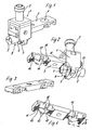
- the terminal of the FIG. 1 has two clamping yokes 1 (also called clamping body), of which for simplicity, only one in FIG. 1 is shown.
- the clamping yoke 1 is preferably bent from a sheet-metal strip and penetrated by a clamping screw 2 on the upper side or on the side facing away from the conductor insertion area.
- the clamping screw 2 is designed here as a screw with hexagon recess for engagement of an Allen key, not shown here. This design ensures that by means of the Allen wrench a particularly high tightening torque can be realized.
- the conductive connection between the two tie bars 1 at the two end portions of the terminal is effected by a busbar 3, which passes through the two clamping yoke 1 and which has on its side facing the clamping screws side recesses 4, which serve to engage the ends of the two clamping screws 2.
- a conductor 5 can be inserted on the side remote from the clamping screw side of the busbar 3.
- each drawbar 1 (in FIG. 1 below) has a concave tapering towards the central axis taper 6, so that two obliquely downwards to Glasbügelstoffschlfitachse outgoing bottom walls 7, 8 result, the intersection of which forms the tapering tip 9, which is preferably formed rounded.
- the bottom walls 7, 8 form a centering for the conductor to be clamped.
- the associated, formed in the illustrated embodiment by the busbar 3 pressure piece is provided at its two ends with corresponding tapers in the form of machined inclined surfaces 10 which converge towards the bottom side of the busbar 3 and in a central, axial material web 11 (flattened or slightly convex trained, if necessary, provided with additional, the ladder supplementary securing ribbing).
- projecting lugs 12 are formed at least at one point, preferably in the middle of the clamping zone, laterally over the inclined surface, which for engaging in a corresponding recess 13 in the bottom walls 7, the eighth the drawbar are formed.
- the elevation 14 is formed in the region of the material web 11 1 as well as in the region of the projections 12 (also embodied as a material web) in the manner of a spherical segment.
- slots 15 may be formed, in which a conductor 5 made of soft material can be additionally pressed.
- the recesses 13 can also be formed without slots directly to the bottom walls 7, 8 via corresponding material connections.
- the busbar 3 in The clamping zones on their side facing the ladder are each provided with convex elevations 14. It can also be connected to one side of the terminal a harder conductor made of copper and on the other side a softer conductor made of aluminum. It is also possible to provide the terminal only in the region of a nip with one of the elevations 14.
- the length and height of the elevations 14 is matched to the conductor to be contacted.
- the length of the elevation 14 in the longitudinal direction of the busbar may be exemplarily greater than the diameter D of the conductor 5 to be connected, or the maximum height of the elevation 14 may in turn be smaller than the radius D / 2 of the smallest conductor 5 to be connected, for example.
- the elevation 14 is preferably formed only in the region of the web 8 and in the region of the webs 11 and lugs 12, so that it has a kind of cross shape in plan view, which in conjunction with the round, spherical design of the elevation surface to a particularly advantageous definition of the connected Porters leads, without that even at higher tightening forces the flow forces is exceeded.
Landscapes
- Connections By Means Of Piercing Elements, Nuts, Or Screws (AREA)
- Connections Effected By Soldering, Adhesion, Or Permanent Deformation (AREA)
Description
- Die Erfindung betrifft eine Anschlussklemme nach dem Oberbegriff des Anspruches 1.
- Die
US 4,213,669 schlägt vor, einen Mehrlitzenleiter mit einer Schraube in einem Zugbügel gegen eine Stromschiene mit einer balligen Erhebung zu pressen. - Eine gattungsgemäße - als Verbindungsklemme ausgestaltete - Anschlussklemme ist aus der
EP 0 082 285 B2 bekannt. - Die in dieser Schrift gezeigte Verbindungsklemme hat sich an sich bewährt. Es besteht aber der Bedarf, ihre Eigenschaft hinsichtlich des Anschlusses weicher Leiter, beispielsweise aus Aluminium, zu verbessern, da die Tendenz dazu besteht, daß beim Beschalten derartiger Leiter nur eine ungenügende Sicherung des Leiters erfolgt. Dies liegt unter anderem daran, daß die Fließgrenze derartiger Leiter beim Anziehen der Schraube mit dem Klemmkörper und/oder temperaturbedingt (u.U. durch Stromfluss oder Witterungseinflüsse verursachte Temperaturwechsel) leicht überschritten wird.
- Die Erfindung löst diese Aufgabe durch den Gegentand des Anspruches 1.
- Die Erhebung drückt sich zwar in den Leiter ein, sticht aber in den Leiter - im Regelfall - nicht scharf das Materialgefüge (zumindest nicht unterhalb der Oxidschicht eines Aluminiumleiters) durchtrennend ein oder schneidet ein sondern verformt diesen lediglich.
- Ganz besonders vorteilhaft ist die in Draufsicht kreuzförmige Geometrie der Erhebung im Bereich der Materialstege und Ansätze.
- Die derart ausgestaltete wenigstens eine Erhebung ermöglicht es, auch weiche Leiter, beispielsweise aus Aluminium oder einer Aluminiumlegierung bestehend, sicher mit der Anschlussklemme der Erfindung schalten zu können. Dabei bleibt einerseits die Zentrierwirkung auf den Leiter erhalten. Andererseits wird durch die Erhebung aber sichergestellt, daß sich beim Festklemmen des Leiters eine vorzugsweise im Vergleich zum Durchmesser des Leiters relativ großflächige Auswölbung mit nicht zu hoher Flächenpressung im Leiter bildet und der Leiter sicher festgeklemmt wird, ohne daß seine Fließgrenze überschritten wird. Ein Fließen des Leiters wird so auf einfache Weise bei kostengünstiger Ausgestaltung verhindert. Die Zentrierwirkung sichert im wesentlichen die Geometrie des Zugbügels. Einschneidende Erhebungen hätten demgegenüber den Nachteil, dass abschnittsweise eine zu hohe Flächenpressung auf den Leiter einwirken würde, was wiederum auf Dauer zu dem bekannten Effekt des Fliessens des Leiters führen würde.
- Erfindungsgemäß sind die Erhebungen im Bereich von Materialstegen und/oder Ansätzen der Stromschiene ausgebildet. Dabei wird eine besonders vorteilhafte Anschlussverbindung realisiert, wenn sich die Erhebungen lediglich über einen Teilbereich der Materialstege und/oder Ansätze erstrecken.
- Nach einer weiteren vorteilhaften Ausgestaltung weisen die Erhebung und die Ausnehmung(en) im Zugbügel eine ineinandergreifende, korrespondierende Geometrie auf, um eine möglichst optimale Zentrierung zu gewährleisten.
- Weitere vorteilhafte Ausgestaltungen sind den übrigen Unteransprüchen zu entnehmen.
- Nachfolgend wird die Erfindung unter Bezug auf die Zeichnungen anhand von Ausfiihrungsbeispielen näher beschrieben. Es zeigt:
- Figur 1
- eine erste perspektivische Ansicht einer Anschlußklemme mit einem dargestellten Klemmkörper;
- Figur 2
- eine zweite perspektivische Ansicht der Anschlußklemme aus
Figur 1 , - Figur 3
- eine erste perspektivische Ansicht einer als Stromschiene dienenden Druckstücks für die Anschlußklemme aus
Figur 1 , - Figur 4
- eine weitere perspektivische Ansicht des Druckstücks aus
Figur 3 . - Die Anschlußklemme der
Figur 1 weist zwei Zugbügel 1 auf (auch Klemmkörper genannt), von denen der Einfachheit halber nur einer inFigur 1 dargestellt ist. - Der Zugbügel 1 ist vorzugsweise aus einem Blechstreifen gebogen und oberseitig bzw. an der vom Leitereinführbereich abgewandten Seite von einer Klemmschraube 2 durchsetzt.
- Die Klemmschraube 2 ist hier als Schraube mit Innensechskantaussparung zum Eingriff eines hier nicht gezeigten Inbusschlüssels ausgelegt. Diese Auslegung stellt sicher, daß mittels des Inbusschlüssels eine besonders hohes Anzugsdrehmoment realisiert werden kann.
- Die leitende Verbindung zwischen den beiden Zugbügeln 1 an den beiden Endbereichen der Anschlussklemme erfolgt durch eine Stromschiene 3, welche die beiden Zugbügel 1 durchsetzt und welche an ihrer den Klemmschrauben zugewandten Seite hier Vertiefungen 4 aufweist, welche zum Eingriff der Enden der zwei Klemmschrauben 2 dienen.
- Zwischen die Stromschiene 3 und den Zugbügel 1 ist auf der von der Klemmschraube abgewandten Seite der Stromschiene 3 ein Leiter 5 einschiebbar.
- Der Bodenbereich jedes Zugbügels 1 (in
Figur 1 unten) weist eine konkave zur Mittelachse hin konvergierende Verjüngung 6 auf, so daß sich zwei schräg nach unten zur Zugbügelmittellängsachse hin verlaufende Bodenwände 7, 8 ergeben, deren Schnittpunkt die Verjüngungsspitze 9 bildet, die vorzugsweise abgerundet ausgebildet ist. Die Bodenwände 7, 8 bilden für den festzuklemmenden Leiter eine Zentrierung. - Das zugehörige, im dargestellten Ausführungsbeispiel durch die Stromschiene 3 gebildete Druckstück ist unterseitig an seinen beiden Enden mit entsprechenden Verjüngungen in Form von eingearbeiteten Schrägflächen 10 versehen, die zur Bodenseite der Stromschiene 3 hin konvergieren und in einen mittigen, axialen Materialsteg 11 (abgeflacht oder leicht konvex ausgebildet, ggf. mit zusätzlicher, den Leiter ergänzend sichernder Riffelung versehen) münden.
- In der Klemmzone im Bereich des Zugbügels bzw. der Schrägflächen 10 sind jeweils an wenigstens an einer Stelle, bevorzugt in der Mitte der Klemmzone, seitlich über die Schrägfläche vorstehende Ansätze 12 ausgebildet, welche zum Eingriff in einer entsprechende Ausnehmung 13 in den Bodenwänden 7, 8 des Zugbügels ausgebildet sind. Dabei ist die Erhebung 14 sowohl im Bereich des Materialsteges 11 1 als auch im Bereich der Ansätze 12(ebenfalls als Materialsteg ausgebildet) kugelabschnittsförmig geformt.
- Zwischen den Bodenwänden 7, 8 und den Ausnehmungen 13 können Schlitze 15 ausgebildet sein, in welche ein Leiter 5 aus weichem Material zusätzlich eingedrückt werden kann. Die Ausnehmungen 13 können aber auch ohne Schlitze direkt an die Bodenwände 7, 8 über entsprechende Materialverbindungen angeformt sein.
- Um den Anschluss weicher Leiter 5 z.B. aus Aluminium zu verbessern, insbesondere von solchen Leitern, welche einen dem Klemmraum angepassten Durchmesser aufweisen, d.h. einen solchen Durchmesser, der ganz oder im wesentlichen den Raum zwischen den Bodenwänden 7, 8 ausfüllt, ist die Stromschiene 3 in den Klemmzonen an ihrer zum Leiter gewandten Seite jeweils mit balligen Erhebungen 14 versehen. Es kann dabei auch an eines Seite der Anschlussklemme ein härterer Leiter aus Kupfer und an die andere Seite ein weichrer Leiter aus Aluminium angeschlossen werden. Es ist auch möglich, die Anschlussklemme nur im Bereich einer Klemmstelle mit einer der Erhebungen 14 zu versehen.
- Es ist vorteilhaft, wenn die Länge und Höhe der Erhebungen 14 auf die zu kontaktierenden Leiter abgestimmt wird. So kann die Länge der Erhebung 14 in Längsrichtung der Stromschiene beispielhaft größer sein als der Durchmesser D des anzuschließenden Leiters 5 oder es kann die maximale Höhe der Erhebung 14 wiederum beispielhaft kleiner sein als der Radius D/2 des kleinsten anzuschließenden Leiters 5.
- Die Erhebung 14 wird vorzugsweise lediglich im Bereich des Steges 8 und im Bereich der Stege 11 und Ansätze 12 ausgebildet, so dass sie in Draufsicht eine Art Kreuzform hat, was in Verbindung mit der runden, balligen Ausgestaltung der Erhebungsoberfläche zu einer besonders vorteilhaften Festlegung des anzuschließenden Leiters führt, ohne dass selbst bei höheren Anzugskräften die Fließkräfte überschritten wird.
-
- Zugbügel
- 1
- Klemmschraube
- 2
- Stromschiene
- 3
- Vertiefung
- 4
- Leiter
- 5
- Verjüngung
- 6
- Bodenwände
- 7, 8
- Verjüngungsspitze
- 9
- Schrägflächen
- 10
- Materialsteg
- 11
- Ansätze
- 12
- Ausnehmung
- 13
- Erhebung
- 14
- Schlitze
- 15
- Riffelung
- 16
Claims (10)
- Anschlussklemme, insbesondere Verbindungsklemme für elektrische Leiter, mit zentrierendem Klemmanschluß, bestehend aus einem hohlen Klemmkörper nach Art eines Zugbügels (1), einer Klemmschraube (2) und einem durch die Klemmschraube (2) bewegbaren Druckstück (3), welches als Stromschiene ausgebildet ist und mit einem Gegendruckstück des Zugbügels (1) einen Leiter festklemmt und leitend kontaktiert, wobei das durch die Stromschiene (3) gebildete Druckstück unterseitig an seinen beiden Enden mit Verjüngungen in Form von eingearbeiteten Schrägflächen (10) versehen ist, die zur Bodenseite der Stromschiene (3) hin konvergieren und in einen mittigen, axialen Materialsteg (11) münden und wobei in der Klemmzone im Bereich des Zugbügels bzw. der Schrägflächen (10) jeweils an wenigstens an einer Stelle seitlich über die Schrägfläche vorstehende Ansätze (12) ausgebildet sind, welche zum Eingriff in eine entsprechende Ausnehmung (13) in Bodenwänden (7, 8) des Zugbügels dienen, dadurch gekennzeichnet, daß die Stromschiene (3) in ihrem vom der Klemmschraube abgewandten Bereich in ihrer Klemmzone mit wenigstens einer balligen, nicht in den Leiter einschneidenden Erhebung (14) versehen ist, welche im Bereich des Materialsteges (11) und/oder der Ansätze (12) ausgebildet ist und welche in Draufsicht eine Kreuzform aufweist.
- Anschlussklemme nach Anspruch 1, dadurch gekennzeichnet, daß der Bodenbereich der Zugbügel (1) eine konkave, zur Mittelachse hin konvergierende Verjüngung (6) aufweist, so daß sich zwei schräg nach unten zur Zugbügelmittellängsachse hin verlaufende Bodenwände (7, 8) ausbilden, deren Schnittpunkt eine Verjüngungsspitze (9) bildet.
- Anschlussklemme nach einem der vorstehenden Ansprüche, dadurch gekennzeichnet, daß zwischen den Bodenwänden (7, 8) und den Ausnehmungen (13) Schlitze (15) ausgebildet sind.
- Anschlussklemme nach einem der vorstehenden Ansprüche, dadurch gekennzeichnet, daß die Ausnehmungen (13) direkt an die Bodenwände (7, 8) über Materialverbindungen angeformt sind.
- Anschlussklemme nach einem der vorstehenden Ansprüche, dadurch gekennzeichnet, daß die Erhebung (14) kugelabschnittsförmig ausgebildet ist.
- Anschlussklemme nach einem der vorstehenden Ansprüche, dadurch gekennzeichnet, daß sich die wenigstens eine Erhebung (14) lediglich über ein Teilbereich des Materialsteges (11) und/oder der Ansätze (12) erstreckt.
- Anschlussklemme nach einem der vorstehenden Ansprüche, dadurch gekennzeichnet, daß die Erhebung (14) und die Ausnehmung(en) (13) im Zugbügel eine ineinandergreifende, korrespondierende Geometrie aufweisen.
- Anschlussklemme nach einem der vorstehenden Ansprüche, dadurch gekennzeichnet, daß die Stromschiene (3) und/oder die wenigstens eine Erhebung (14) aus dem Material des Leiters bestehen.
- Anschlussklemme nach einem der vorstehenden Ansprüche, dadurch gekennzeichnet, daß der Materialsteg (11) konvex ausgebildet und/oder mit einer Riffelung (16) versehen ist.
- Anschlussklemme nach einem der vorstehenden Ansprüche, dadurch gekennzeichnet, daß die Klemmschraube (2) zum Ansetzen eines Inbusschlüssels ausgelegt ist.
Applications Claiming Priority (2)
| Application Number | Priority Date | Filing Date | Title |
|---|---|---|---|
| DE20305314U | 2003-04-01 | ||
| DE20305314U DE20305314U1 (de) | 2003-04-01 | 2003-04-01 | Anschlußklemme, insbesondere Verbindungsklemme |
Publications (2)
| Publication Number | Publication Date |
|---|---|
| EP1465292A1 EP1465292A1 (de) | 2004-10-06 |
| EP1465292B1 true EP1465292B1 (de) | 2012-01-11 |
Family
ID=32842382
Family Applications (1)
| Application Number | Title | Priority Date | Filing Date |
|---|---|---|---|
| EP04004923A Expired - Lifetime EP1465292B1 (de) | 2003-04-01 | 2004-03-03 | Anschlussklemme, insbesondere Verbindungsklemme |
Country Status (3)
| Country | Link |
|---|---|
| EP (1) | EP1465292B1 (de) |
| AT (1) | ATE541337T1 (de) |
| DE (1) | DE20305314U1 (de) |
Families Citing this family (5)
| Publication number | Priority date | Publication date | Assignee | Title |
|---|---|---|---|---|
| DE102005039181B4 (de) * | 2005-08-18 | 2007-05-10 | Siemens Ag | Anschlusssystem mit formschlüssiger Anschlussleitung |
| KR100652241B1 (ko) * | 2005-09-13 | 2006-12-01 | 엘에스산전 주식회사 | 전자접촉기의 단자구조 |
| DE102005061732B4 (de) * | 2005-12-21 | 2015-01-08 | Phoenix Contact Gmbh & Co. Kg | Verfahren zur Bildung einer Struktur an einem Klemmkörper für eine Schraubklemme |
| CN101989686B (zh) * | 2009-07-30 | 2012-12-19 | 淮北钛钴新金属有限公司 | 一种爆炸复合超塑成型电力异形铜铝并沟线夹及其制造方法 |
| DE102020114715A1 (de) * | 2020-06-03 | 2021-12-09 | Phoenix Contact Gmbh & Co. Kg | Schraubanschlussvorrichtung für den elektrischen Anschluss eines Leiters |
Citations (1)
| Publication number | Priority date | Publication date | Assignee | Title |
|---|---|---|---|---|
| US4213669A (en) * | 1978-09-11 | 1980-07-22 | Gte Sylvania Wiring Devices Incorporated | Terminal collar |
Family Cites Families (7)
| Publication number | Priority date | Publication date | Assignee | Title |
|---|---|---|---|---|
| DE1100121B (de) * | 1953-05-13 | 1961-02-23 | Licentia Gmbh | Klemme zum gleichzeitigen Verklemmen mehrerer Leitungen gleichen Querschnitts |
| FR1229919A (fr) * | 1959-03-25 | 1960-09-12 | Cie De Construction Electr | Borne de connexion |
| US3864005A (en) * | 1973-10-11 | 1975-02-04 | Gen Electric | Resilient electrical terminal connector |
| DE3149948A1 (de) * | 1981-12-17 | 1983-07-07 | C.A. Weidmüller GmbH & Co, 4930 Detmold | "verbindungsklemme fuer elektrische leiter" |
| DE8234297U1 (de) * | 1982-12-07 | 1983-06-09 | Flier, Gustav, 7407 Rottenburg | Klemmvorrichtung zum Verbinden von Drähten u.dgl. |
| FR2740911B1 (fr) * | 1995-11-03 | 1998-01-16 | Legrand Sa | Appareil electrique a bornes de raccordement protegees par un diaphragme a fixation par des ailes |
| FR2799312B1 (fr) * | 1999-10-01 | 2001-12-14 | Michaud Sa | Borne de connexion electrique |
-
2003
- 2003-04-01 DE DE20305314U patent/DE20305314U1/de not_active Expired - Lifetime
-
2004
- 2004-03-03 AT AT04004923T patent/ATE541337T1/de active
- 2004-03-03 EP EP04004923A patent/EP1465292B1/de not_active Expired - Lifetime
Patent Citations (1)
| Publication number | Priority date | Publication date | Assignee | Title |
|---|---|---|---|---|
| US4213669A (en) * | 1978-09-11 | 1980-07-22 | Gte Sylvania Wiring Devices Incorporated | Terminal collar |
Also Published As
| Publication number | Publication date |
|---|---|
| DE20305314U1 (de) | 2004-08-19 |
| EP1465292A1 (de) | 2004-10-06 |
| ATE541337T1 (de) | 2012-01-15 |
Similar Documents
| Publication | Publication Date | Title |
|---|---|---|
| EP1885025B1 (de) | Vorrichtung zum elektrischen Verbinden von mindestens zwei Hauptleitern eines Energieversorgungskabels, insbesondere Kabelabzweigklemme | |
| EP1101255B1 (de) | Batteriepolanschlusskabel | |
| EP0082285B1 (de) | Verbindungsklemme für elektrische Leiter | |
| EP0472251B1 (de) | Anordnung zur Verbindung von Sammelschienen | |
| EP3196981A1 (de) | Querverbinder für reihenklemmen | |
| EP3476006A1 (de) | Kupferstromschiene | |
| DE102021213562A1 (de) | Elektrische Kontaktanordnung sowie vorgefertigte Baugruppe | |
| EP4094326B1 (de) | Verbindungsanordnung und verfahren zum verbinden einer verbindungsanordnung mit einem bauteil | |
| DE20305314U1 (de) | Anschlußklemme, insbesondere Verbindungsklemme | |
| CH567338A5 (de) | ||
| DE29815396U1 (de) | Anschlußvorrichtung | |
| EP1037310B3 (de) | Hülsenförmiges Klemmelement zum abisolierfreien Anschluss elektrischer Leiter | |
| DE3728528A1 (de) | Elektrokochplatten-anschlussstueck | |
| EP1137104A2 (de) | Schneid-Klemmkontakt für einen mehrere Drähte aufweisenden Leiter | |
| EP3367507B1 (de) | Klemme zum anschliessen einer elektrischen leitung an eine elektrische schiene | |
| DE2641157A1 (de) | Elektrode fuer die stahlherstellung | |
| DE3332914C2 (de) | Anschlußklemme für Niederspannungsanlagen, insbesondere Schaltgeräte | |
| EP0380980B2 (de) | Vakuumschalter | |
| DE2352430C3 (de) | Elektrische Anschluß- oder/und Verbindungsklemme für insbesondere rohrförmige Leiter | |
| EP2755849B1 (de) | Schleifleitung mit über einen verbinder lösbar verbindbaren stromschienen | |
| EP4208920B1 (de) | Elektrische verbindung für kraftfahrzeugleitung | |
| DE4039430C2 (de) | ||
| DE2164761B1 (de) | Elektrische Verbindungsklemme | |
| DE102020114715A1 (de) | Schraubanschlussvorrichtung für den elektrischen Anschluss eines Leiters | |
| DE285544C (de) |
Legal Events
| Date | Code | Title | Description |
|---|---|---|---|
| PUAI | Public reference made under article 153(3) epc to a published international application that has entered the european phase |
Free format text: ORIGINAL CODE: 0009012 |
|
| AK | Designated contracting states |
Kind code of ref document: A1 Designated state(s): AT BE BG CH CY CZ DE DK EE ES FI FR GB GR HU IE IT LI LU MC NL PL PT RO SE SI SK TR |
|
| AX | Request for extension of the european patent |
Extension state: AL LT LV MK |
|
| 17P | Request for examination filed |
Effective date: 20041021 |
|
| AKX | Designation fees paid |
Designated state(s): AT BE BG CH CY CZ DE DK EE ES FI FR GB GR HU IE IT LI LU MC NL PL PT RO SE SI SK TR |
|
| 17Q | First examination report despatched |
Effective date: 20080728 |
|
| GRAP | Despatch of communication of intention to grant a patent |
Free format text: ORIGINAL CODE: EPIDOSNIGR1 |
|
| GRAS | Grant fee paid |
Free format text: ORIGINAL CODE: EPIDOSNIGR3 |
|
| GRAA | (expected) grant |
Free format text: ORIGINAL CODE: 0009210 |
|
| RAP1 | Party data changed (applicant data changed or rights of an application transferred) |
Owner name: WEIDMUELLER INTERFACE GMBH & CO. KG |
|
| AK | Designated contracting states |
Kind code of ref document: B1 Designated state(s): AT BE BG CH CY CZ DE DK EE ES FI FR GB GR HU IE IT LI LU MC NL PL PT RO SE SI SK TR |
|
| REG | Reference to a national code |
Ref country code: GB Ref legal event code: FG4D Free format text: NOT ENGLISH |
|
| REG | Reference to a national code |
Ref country code: CH Ref legal event code: EP |
|
| REG | Reference to a national code |
Ref country code: AT Ref legal event code: REF Ref document number: 541337 Country of ref document: AT Kind code of ref document: T Effective date: 20120115 |
|
| REG | Reference to a national code |
Ref country code: IE Ref legal event code: FG4D |
|
| REG | Reference to a national code |
Ref country code: DE Ref legal event code: R096 Ref document number: 502004013207 Country of ref document: DE Effective date: 20120308 |
|
| REG | Reference to a national code |
Ref country code: NL Ref legal event code: VDEP Effective date: 20120111 |
|
| PG25 | Lapsed in a contracting state [announced via postgrant information from national office to epo] |
Ref country code: SI Free format text: LAPSE BECAUSE OF FAILURE TO SUBMIT A TRANSLATION OF THE DESCRIPTION OR TO PAY THE FEE WITHIN THE PRESCRIBED TIME-LIMIT Effective date: 20120111 |
|
| PG25 | Lapsed in a contracting state [announced via postgrant information from national office to epo] |
Ref country code: NL Free format text: LAPSE BECAUSE OF FAILURE TO SUBMIT A TRANSLATION OF THE DESCRIPTION OR TO PAY THE FEE WITHIN THE PRESCRIBED TIME-LIMIT Effective date: 20120111 Ref country code: BG Free format text: LAPSE BECAUSE OF FAILURE TO SUBMIT A TRANSLATION OF THE DESCRIPTION OR TO PAY THE FEE WITHIN THE PRESCRIBED TIME-LIMIT Effective date: 20120411 |
|
| REG | Reference to a national code |
Ref country code: IE Ref legal event code: FD4D |
|
| PG25 | Lapsed in a contracting state [announced via postgrant information from national office to epo] |
Ref country code: PL Free format text: LAPSE BECAUSE OF FAILURE TO SUBMIT A TRANSLATION OF THE DESCRIPTION OR TO PAY THE FEE WITHIN THE PRESCRIBED TIME-LIMIT Effective date: 20120111 Ref country code: FI Free format text: LAPSE BECAUSE OF FAILURE TO SUBMIT A TRANSLATION OF THE DESCRIPTION OR TO PAY THE FEE WITHIN THE PRESCRIBED TIME-LIMIT Effective date: 20120111 Ref country code: GR Free format text: LAPSE BECAUSE OF FAILURE TO SUBMIT A TRANSLATION OF THE DESCRIPTION OR TO PAY THE FEE WITHIN THE PRESCRIBED TIME-LIMIT Effective date: 20120412 Ref country code: PT Free format text: LAPSE BECAUSE OF FAILURE TO SUBMIT A TRANSLATION OF THE DESCRIPTION OR TO PAY THE FEE WITHIN THE PRESCRIBED TIME-LIMIT Effective date: 20120511 |
|
| PG25 | Lapsed in a contracting state [announced via postgrant information from national office to epo] |
Ref country code: CY Free format text: LAPSE BECAUSE OF FAILURE TO SUBMIT A TRANSLATION OF THE DESCRIPTION OR TO PAY THE FEE WITHIN THE PRESCRIBED TIME-LIMIT Effective date: 20120111 |
|
| BERE | Be: lapsed |
Owner name: WEIDMULLER INTERFACE G.M.B.H. & CO. KG Effective date: 20120331 |
|
| PG25 | Lapsed in a contracting state [announced via postgrant information from national office to epo] |
Ref country code: RO Free format text: LAPSE BECAUSE OF FAILURE TO SUBMIT A TRANSLATION OF THE DESCRIPTION OR TO PAY THE FEE WITHIN THE PRESCRIBED TIME-LIMIT Effective date: 20120111 Ref country code: EE Free format text: LAPSE BECAUSE OF FAILURE TO SUBMIT A TRANSLATION OF THE DESCRIPTION OR TO PAY THE FEE WITHIN THE PRESCRIBED TIME-LIMIT Effective date: 20120111 Ref country code: DK Free format text: LAPSE BECAUSE OF FAILURE TO SUBMIT A TRANSLATION OF THE DESCRIPTION OR TO PAY THE FEE WITHIN THE PRESCRIBED TIME-LIMIT Effective date: 20120111 Ref country code: MC Free format text: LAPSE BECAUSE OF NON-PAYMENT OF DUE FEES Effective date: 20120331 Ref country code: CZ Free format text: LAPSE BECAUSE OF FAILURE TO SUBMIT A TRANSLATION OF THE DESCRIPTION OR TO PAY THE FEE WITHIN THE PRESCRIBED TIME-LIMIT Effective date: 20120111 Ref country code: SE Free format text: LAPSE BECAUSE OF FAILURE TO SUBMIT A TRANSLATION OF THE DESCRIPTION OR TO PAY THE FEE WITHIN THE PRESCRIBED TIME-LIMIT Effective date: 20120111 Ref country code: IE Free format text: LAPSE BECAUSE OF FAILURE TO SUBMIT A TRANSLATION OF THE DESCRIPTION OR TO PAY THE FEE WITHIN THE PRESCRIBED TIME-LIMIT Effective date: 20120111 |
|
| REG | Reference to a national code |
Ref country code: CH Ref legal event code: PL |
|
| PLBE | No opposition filed within time limit |
Free format text: ORIGINAL CODE: 0009261 |
|
| STAA | Information on the status of an ep patent application or granted ep patent |
Free format text: STATUS: NO OPPOSITION FILED WITHIN TIME LIMIT |
|
| PG25 | Lapsed in a contracting state [announced via postgrant information from national office to epo] |
Ref country code: IT Free format text: LAPSE BECAUSE OF FAILURE TO SUBMIT A TRANSLATION OF THE DESCRIPTION OR TO PAY THE FEE WITHIN THE PRESCRIBED TIME-LIMIT Effective date: 20120111 Ref country code: SK Free format text: LAPSE BECAUSE OF FAILURE TO SUBMIT A TRANSLATION OF THE DESCRIPTION OR TO PAY THE FEE WITHIN THE PRESCRIBED TIME-LIMIT Effective date: 20120111 |
|
| 26N | No opposition filed |
Effective date: 20121012 |
|
| REG | Reference to a national code |
Ref country code: FR Ref legal event code: ST Effective date: 20121130 |
|
| GBPC | Gb: european patent ceased through non-payment of renewal fee |
Effective date: 20120411 |
|
| PG25 | Lapsed in a contracting state [announced via postgrant information from national office to epo] |
Ref country code: LI Free format text: LAPSE BECAUSE OF NON-PAYMENT OF DUE FEES Effective date: 20120331 Ref country code: GB Free format text: LAPSE BECAUSE OF NON-PAYMENT OF DUE FEES Effective date: 20120411 Ref country code: BE Free format text: LAPSE BECAUSE OF NON-PAYMENT OF DUE FEES Effective date: 20120331 Ref country code: CH Free format text: LAPSE BECAUSE OF NON-PAYMENT OF DUE FEES Effective date: 20120331 Ref country code: FR Free format text: LAPSE BECAUSE OF NON-PAYMENT OF DUE FEES Effective date: 20120402 |
|
| REG | Reference to a national code |
Ref country code: DE Ref legal event code: R097 Ref document number: 502004013207 Country of ref document: DE Effective date: 20121012 |
|
| PG25 | Lapsed in a contracting state [announced via postgrant information from national office to epo] |
Ref country code: ES Free format text: LAPSE BECAUSE OF FAILURE TO SUBMIT A TRANSLATION OF THE DESCRIPTION OR TO PAY THE FEE WITHIN THE PRESCRIBED TIME-LIMIT Effective date: 20120422 |
|
| REG | Reference to a national code |
Ref country code: AT Ref legal event code: MM01 Ref document number: 541337 Country of ref document: AT Kind code of ref document: T Effective date: 20120303 |
|
| PG25 | Lapsed in a contracting state [announced via postgrant information from national office to epo] |
Ref country code: AT Free format text: LAPSE BECAUSE OF NON-PAYMENT OF DUE FEES Effective date: 20120303 |
|
| PG25 | Lapsed in a contracting state [announced via postgrant information from national office to epo] |
Ref country code: TR Free format text: LAPSE BECAUSE OF FAILURE TO SUBMIT A TRANSLATION OF THE DESCRIPTION OR TO PAY THE FEE WITHIN THE PRESCRIBED TIME-LIMIT Effective date: 20120111 |
|
| PG25 | Lapsed in a contracting state [announced via postgrant information from national office to epo] |
Ref country code: LU Free format text: LAPSE BECAUSE OF NON-PAYMENT OF DUE FEES Effective date: 20120303 |
|
| PG25 | Lapsed in a contracting state [announced via postgrant information from national office to epo] |
Ref country code: HU Free format text: LAPSE BECAUSE OF FAILURE TO SUBMIT A TRANSLATION OF THE DESCRIPTION OR TO PAY THE FEE WITHIN THE PRESCRIBED TIME-LIMIT Effective date: 20040303 |
|
| PGFP | Annual fee paid to national office [announced via postgrant information from national office to epo] |
Ref country code: DE Payment date: 20230321 Year of fee payment: 20 |
|
| P01 | Opt-out of the competence of the unified patent court (upc) registered |
Effective date: 20230525 |
|
| REG | Reference to a national code |
Ref country code: DE Ref legal event code: R071 Ref document number: 502004013207 Country of ref document: DE |