EP1464908A2 - Fixierung einer Wärmetauscherkassette - Google Patents
Fixierung einer Wärmetauscherkassette Download PDFInfo
- Publication number
- EP1464908A2 EP1464908A2 EP04004158A EP04004158A EP1464908A2 EP 1464908 A2 EP1464908 A2 EP 1464908A2 EP 04004158 A EP04004158 A EP 04004158A EP 04004158 A EP04004158 A EP 04004158A EP 1464908 A2 EP1464908 A2 EP 1464908A2
- Authority
- EP
- European Patent Office
- Prior art keywords
- heat exchanger
- air
- sealing
- slide
- cassette
- Prior art date
- Legal status (The legal status is an assumption and is not a legal conclusion. Google has not performed a legal analysis and makes no representation as to the accuracy of the status listed.)
- Granted
Links
Images

Classifications
-
- H—ELECTRICITY
- H05—ELECTRIC TECHNIQUES NOT OTHERWISE PROVIDED FOR
- H05K—PRINTED CIRCUITS; CASINGS OR CONSTRUCTIONAL DETAILS OF ELECTRIC APPARATUS; MANUFACTURE OF ASSEMBLAGES OF ELECTRICAL COMPONENTS
- H05K7/00—Constructional details common to different types of electric apparatus
- H05K7/20—Modifications to facilitate cooling, ventilating, or heating
- H05K7/20536—Modifications to facilitate cooling, ventilating, or heating for racks or cabinets of standardised dimensions, e.g. electronic racks for aircraft or telecommunication equipment
- H05K7/206—Air circulating in closed loop within cabinets wherein heat is removed through air-to-air heat-exchanger
-
- F—MECHANICAL ENGINEERING; LIGHTING; HEATING; WEAPONS; BLASTING
- F24—HEATING; RANGES; VENTILATING
- F24F—AIR-CONDITIONING; AIR-HUMIDIFICATION; VENTILATION; USE OF AIR CURRENTS FOR SCREENING
- F24F13/00—Details common to, or for air-conditioning, air-humidification, ventilation or use of air currents for screening
- F24F13/30—Arrangement or mounting of heat-exchangers
-
- F—MECHANICAL ENGINEERING; LIGHTING; HEATING; WEAPONS; BLASTING
- F28—HEAT EXCHANGE IN GENERAL
- F28F—DETAILS OF HEAT-EXCHANGE AND HEAT-TRANSFER APPARATUS, OF GENERAL APPLICATION
- F28F9/00—Casings; Header boxes; Auxiliary supports for elements; Auxiliary members within casings
- F28F9/007—Auxiliary supports for elements
Definitions
- the invention relates to a device for fixing and sealing a interchangeable heat exchanger cassette in an air / air heat exchanger, whereby by means of dividers and the heat exchanger cassette two spatially apart separate line areas are formed.
- Such air / air heat exchangers are often used for air conditioning housings Telecommunication systems, IT technology, traffic control technology, industrial outdoor systems, Environmental technology and energy distribution used.
- the heat exchanger can do this at different positions of the housing like on the door, on one of the Side walls or on the roof.
- air / air heat exchangers have an inside and one separate outside air circuit. This is one for air transportation Fan assigned.
- the heat is in a heat exchanger cassette, which in separate channels or fins from the two air flows is flowed through, transferred from the indoor air circuit to the outdoor air circuit. It is it is important that the two air circuits are adequately sealed against each other.
- the sealing elements between the heat exchanger cassette and the housing of the Air / air heat exchangers must not have a sealing effect due to removal and installation to lose. Therefore, in today's air / air heat exchangers, the heat exchanger cassettes glued in or fastened with screwed additional angles.
- the object of the invention is achieved in that the air / air heat exchanger in Area of its dividers has sealing seats that the heat exchanger cassette with Sealing surfaces on the sealing seats and that the air / air heat exchanger has at least one movable slide which the heat exchanger cassette pre-stressed in the sealing seats.
- the slider makes it easy to remove Holding the heat exchanger cassette enables. Because the Heat exchanger cassette is pressed against the sealing seats by the slide on the assigned edges of the heat exchanger cassette a well sealing, but nevertheless easily and repeatedly releasable separation point between the chambers of the Indoor air circuit and those of the outdoor air circuit of the air / air heat exchanger given.
- the slide is by means of an eccentric lever can be actuated.
- the slide can little force is pressed firmly onto the heat exchanger cassette.
- the heat exchanger cassette can be assembled with little effort sufficient pressing force against the sealing seats.
- a uniform contact pressure over the entire length of the sealing surfaces against the Sealing seats is achieved in that the point of action of the eccentric lever transversely to Direction of offset of the slide is positioned in the middle of the slide. Farther this prevents the slide from tilting when the eccentric is tightened.
- the slide is fastened to one of the separating webs and has a bridging section, that the bridging section carries a seal which lies against an associated sealing surface of the heat exchanger cassette, and that the bridging section and the seal cover the transition area between bridge the free end of the separator and the heat exchanger cassette.
- a slight displacement of the slide in the released state and a safe one Fixing the eccentric and thus the slide in the installed state of the Heat exchanger cassette is achieved in that the slide as Sliding guide has a slot-like breakthrough that the breakthrough aligned with a recording in the separator and a recording of the Eccentric lever is arranged, and that a fastening screw through the Breakthrough of the slide and the recordings of the separator and the Eccentric lever is passed and locked with a nut.
- a very good seal on the side of the slide assigned Heat exchanger cassette is achieved in that the slide and the Seals have the same height as the heat exchanger cassette.
- the seals are fixed to the slide and the sealing seats are attached. This enables quick installation and removal the heat exchanger cassette without additional installation effort for positioning of the seals.
- the seals are firmly attached to the Sealing surfaces of the heat exchanger cassette attached. This also enables one quick installation and removal of the heat exchanger cassette without additional Assembly effort for positioning the seals. Furthermore, this Embodiment with the seals when replacing the heat exchanger cassette renewed.
- the Air / air heat exchanger has a housing base on which the Heat exchanger cartridge with a side surface sealingly supports that Separators are connected to the case bottom and rise from it, that the dividers carry the sealing seats which extend parallel to one another, that the slide is essentially perpendicular to the longitudinal extent of the sealing seats It is adjustable that a housing cover parallel to the housing base contains the air / air heat exchanger closes, and that the housing cover is sealed on the Side of the heat exchanger cassette facing away from the housing bottom.
- a preferred variant of the invention provides that the heat exchanger cassette in Top view is constructed symmetically. This allows the heat exchanger cassette Installed in any of the four possible positions without risk of confusion become.
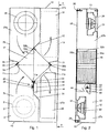
- FIG. 1 shows an air / air heat exchanger 20 in plan view.
- the air / air heat exchanger 20 has a housing, one housing base 12 and four side walls 13 connected to it
- the open housing side can, as can be seen in FIG. 2, with a Housing cover 25 are closed.
- the interior of the housing is four Dividers 21 to 24 divided into four chambers 27 a-d.
- the dividers 21 to 24 are with the housing base 12 and an associated side wall 13 hermetically connected.
- the separating webs extend 21 to 24 over the entire height of the housing interior.
- the dividers 21 to 23 are equipped with sealing seats 32a-c.
- the separator 22 forms a sealing seat 32b with a V-shaped cross section.
- the separators 21 and 23 each form a flat sealing seat 32a and 32c.
- a slide 40 is arranged.
- the slide has one plate-shaped support section 44, which is laterally applied to the separating web 24.
- the support section 44 has at its free end of the separating web 24 protruding area a bridging section, which with an in Cross-section V-shaped sealing seat closes.
- the sealing seat is the V-shaped Sealing seat 32b of the separating web 22 opposite.
- On the sealing seats 32 a-c the Separators 21 to 23 and that of the slide 40 are seals 33 a-c and 34 applied.
- the seals 33 a-c and 34 extend over the entire height of the housing interior.
- a heat exchanger cassette 10 In between the seals 33 a-c and 34 formed receiving space, a heat exchanger cassette 10 can be installed.
- the heat exchanger cassette 10 has a plurality of mutually parallel fins Disconnect line areas. There are two groups of management areas educated. These are alternately two air duct sections of the air / air heat exchanger 20 fed.
- the dividers 21 to 24 divide four chambers 24 a-d in the interior of the housing.
- Two chambers 27a and 27c or 27b and 27d are spatially connected to one another via the heat exchanger cassette 10 and thus form an air duct section.
- the two air duct sections intersect in the area of the heat exchanger cassette 10.
- the first Air guide portion formed by the chambers 27b and 27d is part an internal circuit.
- the second air duct section which is formed by the chambers 27a and 27c is part of an external circuit.
- the internal circuit is over Openings 29 in the housing base 12 of the chambers 27b and 27d in connection with the interior of a connected control cabinet.
- the external circuit is in place through breakthroughs 31 in connection with the environment. Breakthroughs 29 and 31 respectively of the inner and outer circuits is a fan (inner fan 28, outer fan 30) assigned. These promote the air in the internal and external circuit.
- the heat exchanger cassette 10 is in the assembly position shown in FIG. 1 the sealing seats 32 a-c held.
- the slide 40 presses under action an eccentric lever 41, the heat exchanger cassette 10 against the seals 32 a-c and 34.
- the eccentric lever 41 has an opening that is flush with one Breakthrough of the separating web 24 is arranged.
- In the slider 40 is an elongated hole brought in. Through the breakthroughs and the elongated hole one can Fastening screw 43a passed and to form a screw connection be countered with a wing nut.
- a one-piece bent handle section is provided. On this the Eccentric lever 41 can be adjusted. His eccentric section comes into engagement a counter surface of the slide 40 and adjusts it in the direction of the Heat exchanger cassette 10.
Landscapes
- Engineering & Computer Science (AREA)
- Mechanical Engineering (AREA)
- General Engineering & Computer Science (AREA)
- Physics & Mathematics (AREA)
- Thermal Sciences (AREA)
- Chemical & Material Sciences (AREA)
- Combustion & Propulsion (AREA)
- Aviation & Aerospace Engineering (AREA)
- Microelectronics & Electronic Packaging (AREA)
- Heat-Exchange Devices With Radiators And Conduit Assemblies (AREA)
Abstract
Description
Mit dieser einfachen Maßnahme trennt der Schieber im geschlossenen Zustand in Verlängerung des Trennsteges die beiden benachbarten die Luftführungskanäle bildenden Kammern des Luft/Luft-Wärmetauschers ab.
- Fig. 1
- einen Luft/Luft-Wärmetauscher mit einer Wärmetauscherkassette in Draufsicht
- Fig. 2
- den Luft/Luft-Wärmetauscher gemäß Fig. 1 in Ansicht auf den in Fig. 1 mit II-II bezeichneten Schnittverlauf
- Fig.3
- den Luft/Luft-Wärmetauscher gemäß Fig. 1 und 2 einer veranderten Montagestellung und in in Draufsicht
- Fig. 4
- den Luft/Luft-Wärmetauscher gemaß Fig. 3 in Ansicht auf den in Fig. 3 mit IV - IV gezeigten Schnittverlauf
Claims (12)
- Vorrichtung zur Fixierung und Abdichtung einer auswechselbaren Wärmetauscherkassette (10) in einem Luft/Luft-Wärmetauscher (20), wobei mittels Trennstegen (21, 22, 23, 24) und der Wärmetauscherkassette (10) zwei räumlich voneinander getrennte Leitungsbereiche gebildet sind,
dadurch gekennzeichnet, dass der Luft/Luft-Wärmetauscher (20) im Bereich seiner Trennstege (21 bis 24) Dichtsitze (32 a-c) aufweist, dass die Wärmetauscherkassette (10) mit Dichtflächen (11a-d) an den Dichtsitzen anliegt, und dass der Luft/Luft-Wärmetauscher (20) mindestens einen beweglichen Schieber (40) aufweist, der die Wärmetauscherkassette vorgespannt in den Dichtsitzen (32 a-c) hält. - Vorrichtung nach Anspruch 1,
dadurch gekennzeichnet, dass der Schieber (40) mittels eines Exzenterhebels (41) betätigbar ist. - Vorrichtung nach Anspruch 2,
dadurch gekennzeichnet, dass der Einwirkpunkt (42) des Exzenterhebels (41) quer zur Versatzrichtung des Schiebers (40) in der Mitte des Schiebers (40) positioniert ist. - Vorrichtung nach einem der Ansprüche 1 bis 3,
dadurch gekennzeichnet, dass der Schieber (40) an einem der Trennstege (21, 22, 23, 24) befestigt ist und einen Überbrückungsabschnitt aufweist, dass der Überbrückungsabschnitt eine Dichtung (34) trägt, die an einer zugeordneten Dichtfläche (11a) der Wärmetauscherkassette (10) anliegt, und dass der Überbrückungsabschnitt und die Dichtung (34) den Übergangsbereich zwischen dem freien Ende des Trennsteges (21-24) und der Wärmetauscherkassette (10) überbrücken. - Vorrichtung nach Anspruch 4,
dadurch gekennzeichnet, dass der Schieber (40) als Schiebeführung einen langlochartigen Durchbruch aufweist, dass der Durchbruch fluchtend zu einer Aufnahme in dem Trennsteg (24) und einer Aufnahme des Exzenterhebels (41) angeordnet ist, und dass eine Befestigungsschraube (43a) durch den Durchbruch des Schiebers (40) und die Aufnahmen des Trennsteges (24) und des Exzenterhebels (41) hindurchgeführt und mit einer Mutter gekontert ist. - Vorrichtung nach einem der Ansprüche 1 bis 5,
dadurch gekennzeichnet, dass die Dichtsitze (32a-c) mittels an die Dichtflächen (11a-c) der Wärmetauscherkassette (10) angepasste Flächen an den Trennstegen (21, 22, 23) gebildet sind und zwischen den Dichtsitzen (32a-c) und den Dichtflächen (11a-c) Dichtungen (33a-c) angeordnet sind. - Vorrichtung nach einem der Ansprüche 1 bis 6,
dadurch gekennzeichnet, dass zwischen dem Schieber (40) und der als Dichtfläche (11 d) ausgebildeten zugeordneten Kante der Wärmetauscherkassette (10) eine Dichtung (34) mit einem vorzugsweise V-förmigen Profil angeordnet ist. - Vorrichtung nach einem der Ansprüche 1 bis 7,
dadurch gekennzeichnet, dass der Schieber (40) und die Dichtungen (33a-c, 34) die gleiche Höhe wie die Wärmetauscherkassette (10) aufweisen. - Vorrichtung nach einem der Ansprüche 1 bis 8,
dadurch gekennzeichnet, dass die Dichtung (34) fest an dem Schieber (40) und die Dichtungen (33a-c) fest an den Dichtsitzen (32a-c) angebracht sind. - Vorrichtung nach einem der Ansprüche 1 bis 8,
dadurch gekennzeichnet, dass die Dichtungen (33a-c, 34) fest an den Dichtflächen (11a-d) der Wärmetauscherkassette (10) angebracht sind. - Vorrichtung nach einem der Ansprüche 1 bis 10,
dadurch gekennzeichnet, dass der Luft/Luft-Wärmetauscher (20) einen Gehäuseboden (12) aufweist, auf dem sich die Wärmetauscherkassette (10) mit einer Seitenfläche dichtend abstützt, dass die Trennstege (21-24) an den Gehäuseboden (12) angeschlossen sind und von diesem aufsteigen, dass die Trennstege (21-24) die sich zueinander parallel erstreckenden Dichtsitze (32 a-c) tragen, dass der Schieber (40) im wesentlichen senkrecht zur Längserstreckung der Dichtsitze (32 a-c) verstellbar ist, dass parallel zum Gehäuseboden (12) ein Gehäusedeckel (25) den Luft/Luft-Wärmetauscher verschließt, und dass der Gehäusedeckel (25) abgedichtet auf der dem Gehäuseboden (12) abgekehrten Seite der Wärmetauscherkassette (10) aufsitzt. - Vorrichtung nach einem der Ansprüche 1 bis 11,
dadurch gekennzeichnet, dass die Wärmetauscherkassette (10) in Draufsicht symmetrisch aufgebaut ist,
Applications Claiming Priority (2)
| Application Number | Priority Date | Filing Date | Title |
|---|---|---|---|
| DE10315753 | 2003-04-04 | ||
| DE10315753A DE10315753B4 (de) | 2003-04-04 | 2003-04-04 | Fixierung einer Wärmetauscherkassette |
Publications (3)
| Publication Number | Publication Date |
|---|---|
| EP1464908A2 true EP1464908A2 (de) | 2004-10-06 |
| EP1464908A3 EP1464908A3 (de) | 2005-10-12 |
| EP1464908B1 EP1464908B1 (de) | 2010-01-06 |
Family
ID=32842290
Family Applications (1)
| Application Number | Title | Priority Date | Filing Date |
|---|---|---|---|
| EP04004158A Expired - Lifetime EP1464908B1 (de) | 2003-04-04 | 2004-02-24 | Fixierung einer Wärmetauscherkassette |
Country Status (4)
| Country | Link |
|---|---|
| US (1) | US6962191B2 (de) |
| EP (1) | EP1464908B1 (de) |
| JP (1) | JP3929990B2 (de) |
| DE (2) | DE10315753B4 (de) |
Cited By (5)
| Publication number | Priority date | Publication date | Assignee | Title |
|---|---|---|---|---|
| EP1653187A1 (de) * | 2004-10-28 | 2006-05-03 | Recuperator s.r.l. | Eckprofil für Klimaanlage |
| EP1785609A1 (de) * | 2005-11-11 | 2007-05-16 | Modine Manufacturing Company | Wärmetauscher in Plattenbauweise, insbesondere Ladeluftkühler |
| WO2010040432A1 (de) * | 2008-10-08 | 2010-04-15 | Adc Gmbh | Kühlanordnung für einen elektro- oder geräteschrank mit luft-luft-wärmetauscherkassetten |
| US8261816B2 (en) | 2003-12-19 | 2012-09-11 | Modine Manufacturing Company | Heat exchanger with flat tubes |
| US8424592B2 (en) | 2007-01-23 | 2013-04-23 | Modine Manufacturing Company | Heat exchanger having convoluted fin end and method of assembling the same |
Families Citing this family (11)
| Publication number | Priority date | Publication date | Assignee | Title |
|---|---|---|---|---|
| DE102004008460B4 (de) * | 2004-02-17 | 2006-02-02 | Rittal Gmbh & Co. Kg | Anordnung zum Kühlen von Schaltschränken |
| KR100617078B1 (ko) * | 2005-02-07 | 2006-08-30 | 엘지전자 주식회사 | 콤팩트형 환기시스템 |
| US20090250201A1 (en) | 2008-04-02 | 2009-10-08 | Grippe Frank M | Heat exchanger having a contoured insert and method of assembling the same |
| CA2596146A1 (en) * | 2007-08-03 | 2009-02-03 | Air Tech Equipment Ltd. | Heat or energy recovery core support and sealing |
| JP6187485B2 (ja) * | 2015-01-16 | 2017-08-30 | 三菱電機株式会社 | 全熱交換換気装置 |
| JP6202045B2 (ja) * | 2015-05-19 | 2017-09-27 | 三菱電機株式会社 | 全熱交換換気装置 |
| CN107850331B (zh) * | 2015-07-30 | 2020-09-15 | 三菱电机株式会社 | 热交换换气装置 |
| CN204987359U (zh) * | 2015-09-25 | 2016-01-20 | 广东松下环境系统有限公司 | 热交换装置 |
| CN108603676B (zh) * | 2016-02-19 | 2020-12-25 | 三菱电机株式会社 | 热交换换气装置、热交换器的安装方法及热交换器的拆卸方法 |
| CN111895568B (zh) * | 2020-07-31 | 2021-12-17 | 中国农业银行股份有限公司浙江省分行 | 一种沉浸式金融仓的集成新风装置 |
| DE102022110674A1 (de) | 2022-05-02 | 2023-11-02 | Stiebel Eltron Gmbh & Co. Kg | Lüftungsgerät der Haustechnik und Dichtungsteil für ein Lüftungsgerät |
Family Cites Families (13)
| Publication number | Priority date | Publication date | Assignee | Title |
|---|---|---|---|---|
| SE8002896L (sv) * | 1980-04-17 | 1981-10-18 | Bahco Ventilation Ab | Vermeatervinningsanordning |
| US4512392A (en) * | 1983-01-18 | 1985-04-23 | Ee Dirk Van | Heat exchange apparatus |
| JPS63129234A (ja) * | 1986-11-19 | 1988-06-01 | Matsushita Seiko Co Ltd | ダクト用空調換気扇 |
| JPS63194192A (ja) * | 1987-02-04 | 1988-08-11 | Matsushita Seiko Co Ltd | 全熱交換器 |
| JPS6488048A (en) * | 1987-09-28 | 1989-04-03 | Matsushita Seiko Kk | Heat exchanger element holding device |
| JPH05288381A (ja) * | 1992-02-14 | 1993-11-02 | Toshiba Corp | 熱交換ユニットの点検蓋固定装置 |
| JPH0626683A (ja) * | 1992-07-13 | 1994-02-04 | Toshiba Corp | 熱交換換気ユニット |
| JP2830676B2 (ja) * | 1992-11-20 | 1998-12-02 | 三菱電機株式会社 | 換気装置 |
| JPH0972593A (ja) * | 1995-09-07 | 1997-03-18 | Mitsubishi Electric Corp | 熱交換装置 |
| DE19701100C2 (de) * | 1997-01-15 | 1999-10-14 | Autz & Herrmann Maschf | Klimatisierungseinrichtung |
| DE29716682U1 (de) * | 1997-09-17 | 1997-11-06 | Otto Pfannenberg Elektro-Spezialgerätebau GmbH, 21035 Hamburg | Vorrichtung zum Austausch von Wärmeenergie zwischen einem Gehäuseinnenraum und einer Umgebung |
| FI973881A7 (fi) * | 1997-10-03 | 1999-04-04 | Nokia Telecommunications Oy | Elektroniikkakaappi ja elektroniikkakaapin ilmakanavisto |
| DE20007920U1 (de) * | 2000-05-03 | 2000-09-28 | Otto Pfannenberg Elektro-Spezialgerätebau GmbH, 21035 Hamburg | Belüftungsvorrichtung für ein Gehäuse |
-
2003
- 2003-04-04 DE DE10315753A patent/DE10315753B4/de not_active Expired - Fee Related
-
2004
- 2004-02-24 EP EP04004158A patent/EP1464908B1/de not_active Expired - Lifetime
- 2004-02-24 DE DE502004010608T patent/DE502004010608D1/de not_active Expired - Lifetime
- 2004-04-05 US US10/818,465 patent/US6962191B2/en not_active Expired - Fee Related
- 2004-04-05 JP JP2004111450A patent/JP3929990B2/ja not_active Expired - Fee Related
Cited By (6)
| Publication number | Priority date | Publication date | Assignee | Title |
|---|---|---|---|---|
| US8261816B2 (en) | 2003-12-19 | 2012-09-11 | Modine Manufacturing Company | Heat exchanger with flat tubes |
| EP1653187A1 (de) * | 2004-10-28 | 2006-05-03 | Recuperator s.r.l. | Eckprofil für Klimaanlage |
| EP1785609A1 (de) * | 2005-11-11 | 2007-05-16 | Modine Manufacturing Company | Wärmetauscher in Plattenbauweise, insbesondere Ladeluftkühler |
| US8016025B2 (en) | 2005-11-11 | 2011-09-13 | Modine Manufacturing Company | Heat exchanger and method of mounting |
| US8424592B2 (en) | 2007-01-23 | 2013-04-23 | Modine Manufacturing Company | Heat exchanger having convoluted fin end and method of assembling the same |
| WO2010040432A1 (de) * | 2008-10-08 | 2010-04-15 | Adc Gmbh | Kühlanordnung für einen elektro- oder geräteschrank mit luft-luft-wärmetauscherkassetten |
Also Published As
| Publication number | Publication date |
|---|---|
| EP1464908B1 (de) | 2010-01-06 |
| US20040256084A1 (en) | 2004-12-23 |
| JP3929990B2 (ja) | 2007-06-13 |
| US6962191B2 (en) | 2005-11-08 |
| DE10315753B4 (de) | 2005-09-01 |
| EP1464908A3 (de) | 2005-10-12 |
| JP2004309129A (ja) | 2004-11-04 |
| DE502004010608D1 (de) | 2010-02-25 |
| DE10315753A1 (de) | 2004-11-25 |
Similar Documents
| Publication | Publication Date | Title |
|---|---|---|
| EP1464908B1 (de) | Fixierung einer Wärmetauscherkassette | |
| EP1186081B1 (de) | Adapterplatte und system zur anbringung eines bauelementes auf eine montageunterlage | |
| EP0118800A2 (de) | Siebbelag mit auswechselbaren Siebelementen | |
| DE10216913A1 (de) | Anschlussleiste | |
| DE2104050A1 (de) | Klemmhalterung | |
| EP0212158B1 (de) | Profilabtastvorrichtung | |
| DE69622164T2 (de) | Stromschienenverbindung mit mittel zum befestigung einer abdeckung | |
| DE3500258C2 (de) | ||
| EP0154813A1 (de) | Spannvorrichtung für Werkzeugmaschinen | |
| AT413392B (de) | Abstütz- bzw. abstreifeinrichtung für siebbandanlagen | |
| DE202009005193U1 (de) | Vorrichtung zum Befestigen von Leisten | |
| DE102006028764B3 (de) | Fluidsystem | |
| EP0659953A2 (de) | Vorrichtung zum Anbringen von Wandverkleidungen oder dgl. | |
| DE10039072A1 (de) | Ventilanordnung | |
| EP0937951B1 (de) | Befestigungsvorrichtung | |
| DE102009024755A1 (de) | Nummernschildhalterung | |
| DE9413049U1 (de) | Vorrichtung zum Befestigen einer Abdeckleiste für Nuten von Kraftwagen-Aufbauten | |
| DE2347284A1 (de) | Montageplatte zur befestigung von bauteilen elektrischer schaltungen fuer die verwendung in elektrischen schaltschraenken und dergleichen | |
| EP1420493B1 (de) | Kabelrückhalteelement für einen Verdrahtungskanal | |
| DE8500198U1 (de) | Gitterwerkdecke, insbesondere Reinraumgitterwerkdecke | |
| DE102004044268A1 (de) | Vorrichtung zum Abscheiden von mit Öl- und Emulsionsbestandteilen verunreinigten Gasströmen | |
| EP1744420A1 (de) | Schrank, insbesondere Schalt- und/oder Verteilerschrank | |
| DE3206597C2 (de) | Anschluß-Verteiler | |
| DE3740925A1 (de) | Einrichtung zur anbringung einer profilschiene an einem geraetegehaeuse | |
| DE102010018525B4 (de) | Zweistufiger Schwebstofffilter |
Legal Events
| Date | Code | Title | Description |
|---|---|---|---|
| PUAI | Public reference made under article 153(3) epc to a published international application that has entered the european phase |
Free format text: ORIGINAL CODE: 0009012 |
|
| AK | Designated contracting states |
Kind code of ref document: A2 Designated state(s): AT BE BG CH CY CZ DE DK EE ES FI FR GB GR HU IE IT LI LU MC NL PT RO SE SI SK TR |
|
| AX | Request for extension of the european patent |
Extension state: AL LT LV MK |
|
| PUAL | Search report despatched |
Free format text: ORIGINAL CODE: 0009013 |
|
| AK | Designated contracting states |
Kind code of ref document: A3 Designated state(s): AT BE BG CH CY CZ DE DK EE ES FI FR GB GR HU IE IT LI LU MC NL PT RO SE SI SK TR |
|
| AX | Request for extension of the european patent |
Extension state: AL LT LV MK |
|
| 17P | Request for examination filed |
Effective date: 20060412 |
|
| AKX | Designation fees paid |
Designated state(s): DE DK IT |
|
| GRAP | Despatch of communication of intention to grant a patent |
Free format text: ORIGINAL CODE: EPIDOSNIGR1 |
|
| GRAS | Grant fee paid |
Free format text: ORIGINAL CODE: EPIDOSNIGR3 |
|
| GRAA | (expected) grant |
Free format text: ORIGINAL CODE: 0009210 |
|
| AK | Designated contracting states |
Kind code of ref document: B1 Designated state(s): DE DK IT |
|
| REF | Corresponds to: |
Ref document number: 502004010608 Country of ref document: DE Date of ref document: 20100225 Kind code of ref document: P |
|
| PLBE | No opposition filed within time limit |
Free format text: ORIGINAL CODE: 0009261 |
|
| STAA | Information on the status of an ep patent application or granted ep patent |
Free format text: STATUS: NO OPPOSITION FILED WITHIN TIME LIMIT |
|
| 26N | No opposition filed |
Effective date: 20101007 |
|
| PG25 | Lapsed in a contracting state [announced via postgrant information from national office to epo] |
Ref country code: DK Free format text: LAPSE BECAUSE OF FAILURE TO SUBMIT A TRANSLATION OF THE DESCRIPTION OR TO PAY THE FEE WITHIN THE PRESCRIBED TIME-LIMIT Effective date: 20100106 |
|
| REG | Reference to a national code |
Ref country code: DE Ref legal event code: R082 Ref document number: 502004010608 Country of ref document: DE Representative=s name: BOEHMERT & BOEHMERT, DE Ref country code: DE Ref legal event code: R082 Ref document number: 502004010608 Country of ref document: DE Representative=s name: BOEHMERT & BOEHMERT ANWALTSPARTNERSCHAFT MBB -, DE |
|
| PGFP | Annual fee paid to national office [announced via postgrant information from national office to epo] |
Ref country code: IT Payment date: 20230228 Year of fee payment: 20 Ref country code: DE Payment date: 20230216 Year of fee payment: 20 |
|
| REG | Reference to a national code |
Ref country code: DE Ref legal event code: R071 Ref document number: 502004010608 Country of ref document: DE |