EP1464869B1 - Flexible Verbindung zwischen dem Planetenträger und der festen Auflage eines Untersetzungsgetriebes - Google Patents
Flexible Verbindung zwischen dem Planetenträger und der festen Auflage eines Untersetzungsgetriebes Download PDFInfo
- Publication number
- EP1464869B1 EP1464869B1 EP04290814A EP04290814A EP1464869B1 EP 1464869 B1 EP1464869 B1 EP 1464869B1 EP 04290814 A EP04290814 A EP 04290814A EP 04290814 A EP04290814 A EP 04290814A EP 1464869 B1 EP1464869 B1 EP 1464869B1
- Authority
- EP
- European Patent Office
- Prior art keywords
- cage
- gear train
- reduction gear
- radially
- disposed
- Prior art date
- Legal status (The legal status is an assumption and is not a legal conclusion. Google has not performed a legal analysis and makes no representation as to the accuracy of the status listed.)
- Expired - Lifetime
Links
- 239000003638 chemical reducing agent Substances 0.000 title description 11
- 229920001971 elastomer Polymers 0.000 claims description 15
- 239000000806 elastomer Substances 0.000 claims description 15
- 238000001125 extrusion Methods 0.000 claims description 8
- 230000005540 biological transmission Effects 0.000 claims description 5
- 239000000969 carrier Substances 0.000 claims 1
- 238000006073 displacement reaction Methods 0.000 description 3
- 230000000717 retained effect Effects 0.000 description 2
- 239000012080 ambient air Substances 0.000 description 1
- 239000000470 constituent Substances 0.000 description 1
- 230000010339 dilation Effects 0.000 description 1
- 239000013536 elastomeric material Substances 0.000 description 1
- 239000000463 material Substances 0.000 description 1
- 239000002184 metal Substances 0.000 description 1
- 230000002028 premature Effects 0.000 description 1
- 230000000284 resting effect Effects 0.000 description 1
Images




Classifications
-
- F—MECHANICAL ENGINEERING; LIGHTING; HEATING; WEAPONS; BLASTING
- F16—ENGINEERING ELEMENTS AND UNITS; GENERAL MEASURES FOR PRODUCING AND MAINTAINING EFFECTIVE FUNCTIONING OF MACHINES OR INSTALLATIONS; THERMAL INSULATION IN GENERAL
- F16H—GEARING
- F16H1/00—Toothed gearings for conveying rotary motion
- F16H1/28—Toothed gearings for conveying rotary motion with gears having orbital motion
- F16H1/2809—Toothed gearings for conveying rotary motion with gears having orbital motion with means for equalising the distribution of load on the planet gears
- F16H1/2827—Toothed gearings for conveying rotary motion with gears having orbital motion with means for equalising the distribution of load on the planet gears by allowing limited movement of the planet carrier, e.g. relative to its shaft
-
- F—MECHANICAL ENGINEERING; LIGHTING; HEATING; WEAPONS; BLASTING
- F16—ENGINEERING ELEMENTS AND UNITS; GENERAL MEASURES FOR PRODUCING AND MAINTAINING EFFECTIVE FUNCTIONING OF MACHINES OR INSTALLATIONS; THERMAL INSULATION IN GENERAL
- F16H—GEARING
- F16H57/00—General details of gearing
- F16H57/08—General details of gearing of gearings with members having orbital motion
- F16H57/082—Planet carriers
-
- Y—GENERAL TAGGING OF NEW TECHNOLOGICAL DEVELOPMENTS; GENERAL TAGGING OF CROSS-SECTIONAL TECHNOLOGIES SPANNING OVER SEVERAL SECTIONS OF THE IPC; TECHNICAL SUBJECTS COVERED BY FORMER USPC CROSS-REFERENCE ART COLLECTIONS [XRACs] AND DIGESTS
- Y10—TECHNICAL SUBJECTS COVERED BY FORMER USPC
- Y10T—TECHNICAL SUBJECTS COVERED BY FORMER US CLASSIFICATION
- Y10T403/00—Joints and connections
- Y10T403/45—Flexibly connected rigid members
- Y10T403/451—Rigid sleeve encompasses flexible bushing
-
- Y—GENERAL TAGGING OF NEW TECHNOLOGICAL DEVELOPMENTS; GENERAL TAGGING OF CROSS-SECTIONAL TECHNOLOGIES SPANNING OVER SEVERAL SECTIONS OF THE IPC; TECHNICAL SUBJECTS COVERED BY FORMER USPC CROSS-REFERENCE ART COLLECTIONS [XRACs] AND DIGESTS
- Y10—TECHNICAL SUBJECTS COVERED BY FORMER USPC
- Y10T—TECHNICAL SUBJECTS COVERED BY FORMER US CLASSIFICATION
- Y10T403/00—Joints and connections
- Y10T403/45—Flexibly connected rigid members
- Y10T403/454—Connecting pin traverses radially interposed elastomer
Definitions
- the invention relates to a speed reducer, intended in particular to ensure the transmission of torque between a gas turbine and a compressor in a turbomachine.
- a gearbox consists mainly of four elements: a sun gear driven by the shaft of the turbine, a ring gear coaxial to the sun gear, satellites meshing with the sun gear and the crown and a planet carrier.
- the variation of the reduction ratio of such an assembly is obtained by modifying the number of teeth of each of the gears, and the architecture of the gearbox.
- the mobile element of the gearbox either the crown or the planet carrier, is connected to the drive shaft of the gearbox.
- compressor and the other element is connected to the fixed structure of the turbomachine.
- the choice of the configuration of the reducer is therefore done by determining the reduction ratio.
- the major disadvantage of the epicyclic configuration is that despite a smaller footprint than the planetary reducer, the satellites are subjected to a centrifugal field of the order of 2000 g, causing significant difficulties in the bearings supporting the satellites.
- the planet carrier is generally connected to a fixed structure in the case of a planetary gear, or to a transmission shaft, in the case of an epicyclic gearbox, by one of its end faces, the Bearings supporting the satellites, and more generally the planet carrier, are subjected to torsion torques and will deform, and transmit stresses and deformations to the elements to which the planet carrier is fixed. These deformations also cause misalignment of the gears and premature wear of the reducer.
- US Pat. No. 5,391,125 which represents the state of the art closest to the invention, has proposed a speed reducer for the transmission of the torque between a gas turbine and a compressor in an aviation turbine engine, which comprises a sun gear coaxial with the axis of the gearbox and connected to the turbine, a planet carrier connected to the compressor coaxially to the sun gear and on which a plurality of satellites meshing with the sun gear and a ring gear fixed to a structure of the turbomachine and with which the satellites meshing.
- the planet carrier comprises an annular cage having a plurality of seats for supporting bearings parallel to the axis of the gearbox and each of which journalled one of the satellites, and a plurality of axial housings each arranged between two adjacent satellites, and, on the other hand, an annular cage carrier connected to the compressor and having a plurality of axial arms, each arm being disposed in one of the housing of the cage and being attached to an adjacent portion of the cage by a pin disposed in the median radial plane of the cage.
- Each pin arranged perpendicular to the axis of the gearbox, is inserted into a hole in the corresponding arm and two holes formed radially on either side of the arm in an axial wall of the cage with the interposition of bearings.
- This embedding type connection allows no cant or axial displacement between the cage and the cage-carrier, which can occur in a turbomachine, particularly aviation, due to vibrations due to turbulence of the ambient air and dilations thermal.
- the gearbox according to the invention differs from this state of the art in that the arm housings are arranged radially at the intersection of the forces of the adjacent satellites, and in that each pin for fixing an arm on the adjacent portion of the cage is rigidly fixed to one of the pieces constituted by said arm and said cage portion and is mounted on the other piece by a flexible connection comprising a sleeve surrounding the pin and disposed in an orifice of the other piece, said sleeve having two annular end flanges and a plurality of coaxial sleeves disposed between said flanges, at least one of said sleeves being made of an elastomer to provide flexibility.
- This arrangement makes it possible to induce flexibility in the planetary / satellite and satellite / crown links. This has the advantage, not negligible, of reducing the misalignment in the tooth contacts.
- This elastomer sleeve ensures if necessary the spill of the cage relative to the cage holder connected to the first element.
- the annular end flanges of the sleeve each have a radially internal rebate and a radially outer rebate facing each other, said rebates being separated by an annular rib
- the lampholders comprise a rigid inner ring whose ends enclose in the radially inner grooves of the flanges, a rigid outer ring which extends between the radially outer flanges of the flanges and which has at its ends radially internal grooves facing the radially outer flanges of the flanges, and the elastomer sleeve is interposed between the inner ring and the outer ring and extends between the ribs of the flanges.
- the annular chambers delimited by the radially outer rabbets of the flanges and the radially inner grooves of the outer ring contain elastic joints.
- Each of the annular chambers also contains an anti-extrusion ring for preventing extrusion of the elastomer, said anti-extrusion ring being interposed between an elastic seal and the end face of the radially inner groove of the outer ring.
- one of the flanges of the sleeve bears against the part on which the pin is fixed, and the other flange is pressed against the inner ring by a nut cooperating with a thread of the pin.
- the pin is rigidly connected to the corresponding arm and is arranged perpendicularly to the axis of the reducer.
- the pin is formed at the end of the arm and is parallel to the axis of the reducer.
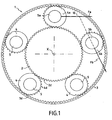
- FIGS. 1 and 2 show an X-axis reduction gear 1, which comprises an X-axis sun gear 2 having on its periphery a toothing 2d, an X-axis ring 3 having a diameter greater than diameter of the sun gear 2 and having on its radially inner wall a toothing 3d, and between the sun gear 2 and the ring gear 3, a plurality of satellites 4, 5 in number in Figure 1, having on their periphery a toothing 4d meshing with the 2d and 3d teeth of the sun gear 2 and the crown 3.
- X-axis reduction gear 1 which comprises an X-axis sun gear 2 having on its periphery a toothing 2d, an X-axis ring 3 having a diameter greater than diameter of the sun gear 2 and having on its radially inner wall a toothing 3d, and between the sun gear 2 and the ring gear 3, a plurality of satellites 4, 5 in number in Figure 1, having on their periphery a toothing 4d meshing with the 2d and
- the satellites 4 are mounted journalling on bearings 5 parallel to the X axis whose ends are mounted in pairs of seats provided vis-a-vis in two side flanges 7a and 7b of a cage 8 supporting the satellites 5, the two side flanges 7a and 7b being rigidly connected by bridges 9 arranged between two neighboring satellites.
- the bridges 9 and one of the side flanges 7a are made in one piece, constituting the support housing at the bearings 5 of the satellites 4, and the other side flange 7b is in the form of a clevis serving axial bearing to all the bearings 5 of the satellites 4.
- the bearings 5, five in number in the drawings, are regularly spaced around the axis X of the gearbox 1 and are arranged halfway between the teeth 2d and 3d .
- each bearing 5 is subjected to a force perpendicular to the plane containing the axis X and the axis of said bearing and whose intensity is equivalent at twice the tangential effort generated by a meshing.
- the arrow represented by the arrow F is the force supported by the landing 5 a of the satellite 4 a and by the arrow F b the force supported by the landing 5 b of the satellite 4 b adjacent to the satellite 4 a.
- These two forces Fa and Fb intersect at a point 10 located inside the diameter of the ring 3, and in the median radial plane of the cage 8.
- the bridges 9 and at least one of the lateral flanges 7a and 7b have axial housings 11 each enclosing an intersection point 10 of the lines of the forces Fa and Fb of two adjacent satellites 4a, 4b.
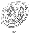
- Reference numeral 12 designates an annular cage carrier, visible in FIG. 2, of axis X, which comprises on its front face 13 a plurality of arm 14, five in the example shown in the drawings, parallel to the axis X and each housing an axial housing 11.
- Each arm 14 is fixed to the adjacent bridge 9 by a pin 15 whose geometric axis is perpendicular to the axis X of the gear unit 1 and cuts the latter.
- the pin 15 is rigidly fixed on the arm 14 and is connected to the adjacent bridge 9 by a finger-type spherical connection which radially immobilizes the cage holder 12, but allows to a certain extent a cant of the cage carrier 12 or a slight axial displacement of the latter relative to the cage 8, to induce flexibility in the links between the sun gear 2 and the satellites 4 and between the satellites 4 and the crown 3. This has the advantage, not negligible, to reduce the misalignment in the contact of the teeth 2d, 4d and 3d.
- the geometric axes of the pins 15 are located in the median radial plane of the satellites 4 and pass through the points of intersection 10 of the forces Fa and Fb of two adjacent bearings 5a, 5b.
- Figure 5 shows in perspective the cage holder 12 alone.
- the arms 14 have a substantially rectangular section and each comprises at their end a radial hole 16 to receive the radially outer portion of the spindle 15.
- the corresponding bridge 9 comprises a radial orifice 17 in which is disposed a sleeve 20 surrounding the radially inner portion of the pin 15, as shown in FIG. 6, this sleeve 20 being retained on the pin 15 by a nut 21 which cooperates with a thread provided on the radially inner end of the pin 15.
- the sleeve 20 shown in detail in FIG. 7 comprises two annular end flanges, referenced 22 and 23, at least three coaxial sleeves, 24, 25 and 26, interposed between the annular flanges 22 and 23, the intermediate bushing 25 being made in an elastomeric material.
- the radially inner sleeve 24, as well as the annular flanges 22 and 23 have an inner diameter equal to the outer diameter of the pin 15 and the ends of the inner sleeve 24 are arranged in rabbets formed vis-à-vis in the annular flanges 22 and 23.
- the elastomer sleeve 25 is disposed between the inner sleeve 24 and the outer sleeve 26 and between the end annular flanges 22 and 23.
- the radially outer sleeve 26 has a diameter outer diameter equal to the diameter of the orifice 17 of the bridge 9. This outer sleeve 26 is hooped in the orifice 17, and it traps the elastomer sleeve 25. Elastic joints 28 and 29 are interposed between the annular flanges 22 and 23, and the radially inner wall of the orifice 17 or the ends of the radially outer sleeve 26, to allow a lateral cant or displacement of the outer sleeve 26 relative to the inner sleeve 24, by deformation of the elastomer sleeve 25 .
- Anti-extrusion rings, referenced 30 and 31 are interposed between the elastic joints 28 and 29 and a front surface of the outer sleeve 26.
- the inner bushings 24 and outer 26 are made in the form of rigid metal rings.
- the anti-extrusion rings 30 and 31 serve to maintain the constituent material of the elastomer bushing 25 in the annular space which is provided for the latter.
- the radially outer portion of the pin 15 is hooped in the hole 16 of the arm 14 with the interposition of a bearing 32, shown in Figure 6.
- This radially outer portion has an enlarged head 33.
- Figures 8 and 9 show a preferred embodiment of the sleeve 20, which differs from the sleeve 20 shown in Figure 7 in that the annular end plates 22 and 23 have, each vis-à-vis, a rabbet radially inner 40 and a radially outer rabbet 41, separated by an annular rib 42.
- the outer diameter of the radially inner rabbet 40 is equal to the outside diameter of the inner sleeve or ring 24.
- the ends of the inner ring 24 are disposed after mounting in the radially inner rabbets 40.
- the elastomer bushing 25 whose height is less than the height of the inner ring is disposed between the annular ribs 42 of the annular flanges 22 and 23.
- the sleeve or outer ring 26 whose height is greater than the height of the inner ring 24, has at its ends radially internal grooves, referenced 43 and 44, separated by a ring height substantially equal to the height of the elastomer sleeve 25.
- the radially internal grooves 43 and 44 of the outer ring are arranged after mounting opposite the radially outer rabbets 41 of the end annular flanges 22 and 23 and define therewith annular chambers referenced 45 and 46, visible in FIG. each housing a seal 28, 29 and an anti-extrusion ring 30, 31.
- the diameters of the radially inner grooves 43 and 44 are slightly greater than the outer diameter of the annular flanges 22 and 23, and the ends of the outer ring 26 loosely surround the annular flanges 22 and 23 to allow deformation of the elastomer bushing. 25 and a misalignment between the inner and outer rings 24 and 26.
- the point 10 intersection of the forces supported by the bearings 5a, 5b of two neighboring satellites 4a and 4b is preferably located in the central zone of the sleeve 20.
- the force supported by the pin 15 and the sleeve 20 is thus a perpendicular radial force to the axis of the spindle 15, which does not result in torsion torque at the spherical finger connection.
- the inner ring 24 is hooped on the pin 15 and the outer ring 26 is hooped on the bridge 9.
- the spindle 15 is hooped on the arm 14, and the spherical finger connection is disposed between the spindle 15 and the bridge 9. It is obvious to those skilled in the art that the spindle 15 could be hooped on the bridge 9, and that the spherical finger connection would then be disposed between the pin 15 and the arm 14.
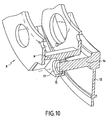
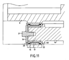
- Figures 10 and 11 show an alternative embodiment of the invention which differs from that described above in that the pin 15 is formed at the end of the arm 14 and is parallel to the axis X of the gear unit 1.
- the corresponding bridge 9 has an orifice 17 disposed in the median plane of the cage 8, and in which is disposed a sleeve 20 according to that described above with reference to Figure 9.
- the sleeve 20 surrounds the pin 15 and the flange annular 22 is in abutment against an annular shoulder 50 formed on the arm 14.
- the sleeve 20 is retained on the spindle 15 by a nut 21 resting on a washer 51, itself bearing on the annular flange 23.
- the reducer 1 described above has a particular application in the drive of a compressor by a turbine in an aviation turbine engine.
- the sun gear 2 is connected to the shaft of the turbine.
- the cage carrier 12 is then connected to the fixed structure of the turbomachine and the ring gear 3 is connected to the drive shaft of the compressor, in the case of a planetary gearbox.
- the cage carrier 12 is connected to the drive shaft of the compressor in the case of an epicyclic gearbox, the ring gear 3 then being connected to the fixed structure of the turbomachine.
Landscapes
- Engineering & Computer Science (AREA)
- General Engineering & Computer Science (AREA)
- Mechanical Engineering (AREA)
- Retarders (AREA)
- General Details Of Gearings (AREA)
Claims (9)
- Untersetzungsgetriebe mit einem Zentralrad (2), das koaxial zur Achse dieses Untersetzungsgetriebes angeordnet ist, einem Planetenträger, an dem ein Vielzahl von Planetenrädern (4) sitzen, die sich mit diesem Zentralrad (2) in Eingriff befinden, und mit einem Zahnkranz (3), mit dem sich diese Planetenräder in Zahneingriff befinden, wobei dieser Planetenträger einerseits einen ringförmigen Käfig (8) mit einer Vielzahl von paarweise angeordneten Sitzen, um Lager (5) parallel zur Achse dieses Untersetzungsgetriebes zu halten, auf denen jeweils eines dieser Planetenräder (4) dreht, sowie eine Vielzahl von axialen Aufnahmen (11), die jeweils zwischen zwei aneinandergrenzenden Planetenrädern (4a, 4b) angeordnet sind, und andererseits einen ringförmigen Käfigträger (12) mit einer Vielzahl von axialen Armen (14) umfasst, wobei jeder Arm (14) in einer dieser Aufnahmen (11) angeordnet ist und an einem angrenzenden Abschnitt (9) dieses Käfigs (8) mittels eines Stifts (15) befestigt ist, der im Wesentlichen in der radialen Mittelebene dieses Käfigs angeordnet ist,
dadurch gekennzeichnet,
dass die Aufnahmen (11) der Arme (14) radial am Schnittpunkt der Kraftlinien der aneinandergrenzenden Planetenräder (4a, 4b) angeordnet sind, und dass jeder Stift (15) zur Befestigung eines Arms (14) an dem angrenzenden Abschnitt (9) des Käfigs (8) starr an einem der von diesem Arm (14) und diesem Käfigabschnitt (9) gebildeten Teile befestigt ist und an dem anderen Teil durch eine flexible Verbindung angebracht ist, welche eine Muffe (20) umfasst, die den Stift (15) umgibt und in einer Öffnung (17) des anderen Teils angeordnet ist, wobei diese Muffe (20) zwei ringförmige Endflansche (22, 23) und mehrere zwischen diesen Flanschen angeordnete koaxiaic Hülsen (24, 25, 26) enthält, wobei mindestens eine dieser Hülsen (25) aus einem hergestellt ist, um die Flexibilität zu gewährleisten. - Untersetzungsgetriebe nach Anspruch 1,
dadurch gekennzeichnet,
dass die ringförmigen Endflansche (22, 23) der Muffe (20) jeweils einen, radial inneren Falz (40) und einen radial äußeren Falz (41) aurweisen, wobei diese Falze durch eine ringförmige Rippe (42) voneinander getrennt sind, und dass die Hülsen einen starren Innenring (24), dessen Enden in den radial inneren Falzen (40) der Flansche (22, 23) Aufnahme finden, und einen starren Außenring (26) umfassen, der sich zwischen den radial äußeren Falzen (41) der Flansche (22, 23) erstreckt und an seinen Enden radial innere Rillen (43, 44) aufweist, die den radial äußeren Falzen (41) der Flansche (22, 23) gegenüber liegen, und die Elastomerhülse (25) zwischen dem Innenring (24) und dem Außenring (26) angeordnet ist und sich zwischen den Rippen (42) der Flansche erstreckt. - Untersetzungsgetriebe nach Anspruch 2,
dadurch gekennzeichnet,
dass von den radial äußeren Falzen (41) der Flansche und den radial inneren. Rillen (43, 44) des Außenrings (26) ringförmige Kammern (45,46) umgrenzt werden, wobei diese Kammern elastische Dichtungen (28, 29) umschließen. - Untersetzungsgetriebe nach Anspruch 3,
dadurch gekennzeichnet,
dass jede der ringförmigen Kammern (45,46) ferner einen Pressschutzring (30, 31) umschließt, der dazu vorgesehen ist, das Herauspressen des Elastomers zu verhindern, wobei dieser Pressschutzring (30, 31) zwischen einer elastische Dichtung (28, 29) und der Vorderseite der radial inneren. Rille (43, 44) des Außenrings (26) angeordnet ist. - Untersetzungsgetriebe nach einem der Ansprüche 2 bis 4,
dadurch gekennzeichnet,
dass sich einer der Flansche (22) der Muffe (20) in Anlage an dem Teil befindet, an dem der Stift (15) befestigt ist, und der andere Flansch (23) durch eine Mutter (21), die mit einem Gewinde des Stifts (15) zusammenwirkt, gegen den Innenring (24) gedrückt wird. - Untersetzungsgetriebe nach einem der Ansprüche 1 bis 5,
dadurch gekennzeichnet,
dass der Stift (15) starr mit dem entsprechenden Arm (14) verbunden ist und im rechten Winkel zur Achse des Untersetzungsgetriebes angeordnet ist. - Untersetzungsgetriebe nach einem der Ansprüche ! 1 bis 5,
dadurch gekennzeichnet,
dass der Stift (15) am Ende des Arms (14) ausgebildet ist und parallel zur Achse des Untersetzungsgetriebes angeordnet ist. - Turbotriebwerk mit einem Verdichter, einer Gasturbine und einem Untersetzungsgetriebe zur Kraftübertragung zwischen dieser Gasturbine und diesem. Verdichter, dieses Untersetzungsgetriebe ein Zentralrad (2) enthält, das koaxial zur Achse dieses t Jntcrscizungsgetriebcs angeordnet ist und mit dieser Turbine ist, sowie einen PIanetenträger enthält, der koaxial zu diesem Zentralrad (2) mit einem ersten Element dieses Turbotriebwcrks verbunden ist und an dem eine Vielzahl von Planetenrädern (4) sitzen, die sich mit diesem Zentralrad (2) in Eingriff befinden, sowie einen Zahnkranz (3) enthält, der an einem zweiten Element dieses Turbotriebwerks befestigt ist und mit dem sich diese Planetenräder in Zahneingriff befinden, wobei eines von diesen ersten und zweiten Elementen einen festen Aufbau des Turbotriebwerks bildet und das andere von diesen Elementen den Verdichter in Drehbewegung versetzt, wobei dieser Planetenträger einerseits einen ringförmigen Käfig (8) mit einer Vielzahl von paarweise angeordneten Sitzen, um Lager (5) parallel zur Achse dieses Untersetzungsgetriebes zu halten, auf denen j jeweils eines dieser Planetenräder (4) dreht, sowie eine Vielzahl von axialen Aufnahmen (11), die jeweils zwischen zwei aneinandergrenzenden Planetenrädern (4a, 4b) angeordnet sind, und andererseits einen mit diesem ersten Element verbundenen ringförmigen Käfigträger (12) mit einer Vielzahl von axialen Armen (14) umfasst, wobei jeder Arm (14) in einer dieser Aufnahmen (11) angeordnet ist und an einem angrenzenden Abschnitt (9) dieses Käfigs (8) mittels eines Stifts (15) befestigt ist, der im Wesentlichen in der radialen Mittelebene dieses Käfigs angeordnet ist,
dadurch gekennzeichnet,
dass die Aufnahmen (11) der Arme (14) radial am Schnittpunkt der Kraftlinien der aneinandergrenzenden Planetenräder (4a, 4b) angeordnet sind, und dass jeder Stift (15) zur Befestigung eines Arms (14) an dem angrenzenden Abschnitt (9) des Käfigs (8) starr an einem der von diesem Arm (14) und diesem Käfigabschnitt (9) gebildeten Teile befestigt ist und an dem anderen Teil durch eine flexible Verbindung angebracht ist, welche eine Muffe (20) umfasst, die den Stift (15) umgibt und in einer Öffnung (17) des anderen Teils angeordnet ist, wobei diese Muffe (20) zwei ringförmige. Endflansche (22, 23) und mehrere zwischen diesen Flanschen angeordnete koaxiale Hülsen (24, 25, 26) enthält, wobei mindestens eine dieser Hülsen (25) aus einem Elastomer hergestellt ist, um die Flexibilität zu gewährleisten. - Turbotriebwerk nach Anspruch 8,
dadurch gekennzeichnet,
dass der Kranz (3) an dem festen Aufbau des Turbotriebwerks befestigt ist und der Käfigträger (12) den Verdichter in Drehbewegung versetzt.
Applications Claiming Priority (2)
| Application Number | Priority Date | Filing Date | Title |
|---|---|---|---|
| FR0304186 | 2003-04-04 | ||
| FR0304186A FR2853382B1 (fr) | 2003-04-04 | 2003-04-04 | Systeme de liaison souple entre un porte-satellites et le support fixe dans un reducteur de vitesse |
Publications (2)
| Publication Number | Publication Date |
|---|---|
| EP1464869A1 EP1464869A1 (de) | 2004-10-06 |
| EP1464869B1 true EP1464869B1 (de) | 2006-07-12 |
Family
ID=32843139
Family Applications (1)
| Application Number | Title | Priority Date | Filing Date |
|---|---|---|---|
| EP04290814A Expired - Lifetime EP1464869B1 (de) | 2003-04-04 | 2004-03-26 | Flexible Verbindung zwischen dem Planetenträger und der festen Auflage eines Untersetzungsgetriebes |
Country Status (8)
| Country | Link |
|---|---|
| US (1) | US7011599B2 (de) |
| EP (1) | EP1464869B1 (de) |
| JP (1) | JP4549718B2 (de) |
| CA (1) | CA2462933C (de) |
| DE (1) | DE602004001476T2 (de) |
| FR (1) | FR2853382B1 (de) |
| RU (1) | RU2332598C2 (de) |
| UA (1) | UA81609C2 (de) |
Cited By (2)
| Publication number | Priority date | Publication date | Assignee | Title |
|---|---|---|---|---|
| EP3284976B1 (de) | 2016-08-19 | 2020-05-06 | Flender GmbH | Planetenträger |
| EP3710727B1 (de) * | 2017-11-17 | 2022-01-26 | Safran Transmission Systems | Turbomaschinengetriebe mit planetengetriebe |
Families Citing this family (80)
| Publication number | Priority date | Publication date | Assignee | Title |
|---|---|---|---|---|
| FR2902822B1 (fr) * | 2006-06-21 | 2008-08-22 | Snecma Sa | Palier pour aube de stator a calage variable |
| US7704178B2 (en) | 2006-07-05 | 2010-04-27 | United Technologies Corporation | Oil baffle for gas turbine fan drive gear system |
| US8667688B2 (en) | 2006-07-05 | 2014-03-11 | United Technologies Corporation | Method of assembly for gas turbine fan drive gear system |
| US8585538B2 (en) | 2006-07-05 | 2013-11-19 | United Technologies Corporation | Coupling system for a star gear train in a gas turbine engine |
| US7926260B2 (en) * | 2006-07-05 | 2011-04-19 | United Technologies Corporation | Flexible shaft for gas turbine engine |
| US9194255B2 (en) | 2006-07-05 | 2015-11-24 | United Technologies Corporation | Oil baffle for gas turbine fan drive gear system |
| US7828687B2 (en) * | 2006-10-25 | 2010-11-09 | Remy Technologies, L.L.C. | Modular planetary gear assembly and drive |
| WO2009052824A2 (en) * | 2007-10-22 | 2009-04-30 | Vestas Wind Systems A/S | Epicyclic gear stage for a wind turbine gearbox, a wind turbine gearbox and a wind turbine |
| ATE511018T1 (de) * | 2007-12-20 | 2011-06-15 | Vestas Wind Sys As | Planetengetriebestufe für ein windturbinengetriebe, windturbinengetriebe und windturbine |
| DE102008063044B4 (de) * | 2008-12-23 | 2012-01-05 | Aerodyn Engineering Gmbh | Planetengetriebe |
| US8672801B2 (en) | 2009-11-30 | 2014-03-18 | United Technologies Corporation | Mounting system for a planetary gear train in a gas turbine engine |
| KR20120054559A (ko) * | 2010-08-31 | 2012-05-30 | 다이도 메탈 고교 가부시키가이샤 | 유성 기어 기구, 베어링 구조, 풍력 발전 장치 및 유성 기어의 제조 방법 |
| ITTO20111007A1 (it) * | 2011-11-03 | 2013-05-04 | Avio Spa | Rotismo epicicloidale |
| US9017010B2 (en) | 2012-01-31 | 2015-04-28 | United Technologies Corporation | Turbomachine geared architecture support assembly |
| US8961112B2 (en) | 2012-03-26 | 2015-02-24 | United Technologies Corporation | Torque frame bushing arrangement for gas turbine engine fan drive gear system |
| US20130269479A1 (en) * | 2012-04-11 | 2013-10-17 | General Electric Company | Gearbox and support apparatus for gearbox carrier |
| US9267389B2 (en) * | 2012-06-05 | 2016-02-23 | United Technologies Corporation | Geared architecture carrier torque frame assembly |
| US9328818B2 (en) | 2012-09-21 | 2016-05-03 | United Technologies Corporation | Gear carrier flex mount lubrication |
| JP6078160B2 (ja) | 2012-09-28 | 2017-02-08 | ユナイテッド テクノロジーズ コーポレイションUnited Technologies Corporation | ガスタービンファン駆動ギアシステムの組立方法 |
| FR2999673B1 (fr) * | 2012-12-19 | 2016-07-22 | Chassis Brakes Int Bv | "porte-satellites pour un actionneur electromecanique de frein de stationnement, actionneur et procedes d'assemblage" |
| US8857149B1 (en) | 2013-08-26 | 2014-10-14 | United Technologies Corporation | Torque connector lubrication scuppers |
| FR3011901B1 (fr) | 2013-10-10 | 2017-02-10 | Hispano-Suiza | Porte-satellites pour un reducteur de vitesse a train epicycloidal |
| US10526909B2 (en) * | 2014-01-20 | 2020-01-07 | United Technologies Corporation | Lightweight journal support pin |
| DE102014208793A1 (de) * | 2014-05-09 | 2015-11-12 | Zf Friedrichshafen Ag | Planetenradsatz |
| JP6635502B2 (ja) * | 2014-09-17 | 2020-01-29 | ジーイー・アーヴィオ・ソチエタ・レスポンサビリタ・リミタータGe Avio Srl | 遊星歯車装置のための遊星キャリア、及び、当該遊星キャリアを具備する遊星歯車装置 |
| US10221771B2 (en) * | 2014-09-24 | 2019-03-05 | United Technologies Corporation | Fan drive gear system |
| US10823060B2 (en) * | 2015-12-18 | 2020-11-03 | Raytheon Technologies Corporation | Gas turbine engine with short inlet, acoustic treatment and anti-icing features |
| WO2017139944A1 (zh) * | 2016-02-18 | 2017-08-24 | 深圳市兆威机电有限公司 | 微型齿轮箱及其输出轴 |
| GB2548140B (en) * | 2016-03-10 | 2019-05-29 | Rolls Royce Plc | Transmission system |
| WO2017176176A1 (en) * | 2016-04-05 | 2017-10-12 | Volvo Construction Equipment Ab | A planet carrier and a planetary gear transmission |
| US10082203B2 (en) * | 2016-05-20 | 2018-09-25 | United Technologies Corporation | Low-cost epicyclic gear carrier and method of making the same |
| FR3052213B1 (fr) * | 2016-06-07 | 2018-05-18 | Safran Transmission Systems | Procede d'assemblage d'un porte-satellites |
| JP6867123B2 (ja) * | 2016-08-12 | 2021-04-28 | 川崎重工業株式会社 | 遊星歯車減速装置 |
| US10006520B2 (en) | 2016-08-31 | 2018-06-26 | General Electric Company | System for regulating stresses in ring gears |
| FR3058771B1 (fr) * | 2016-11-14 | 2020-02-28 | Safran Electronics & Defense | Dispositif de transmission mecanique |
| IT201600130715A1 (it) * | 2016-12-23 | 2018-06-23 | Comau Spa | "Dispositivo funzionale, in particolare robot, a moduli componibili per uso educativo" |
| FR3071023B1 (fr) * | 2017-09-12 | 2021-02-19 | Safran Trans Systems | Pivot pour palier lisse |
| DE102017127876A1 (de) | 2017-11-24 | 2019-05-29 | Rolls-Royce Deutschland Ltd & Co Kg | Planetengetriebe und Gleitlagerstift für ein Planetengetriebe |
| EP3489549B1 (de) | 2017-11-24 | 2022-01-05 | Rolls-Royce Deutschland Ltd & Co KG | Planetengetriebe und gleitlagerstift für ein planetengetriebe |
| DE102017127874A1 (de) * | 2017-11-24 | 2019-05-29 | Rolls-Royce Deutschland Ltd & Co Kg | Planetengetriebe und Planetenrad für ein Planetengetriebe |
| EP3489548B1 (de) | 2017-11-24 | 2022-01-05 | Rolls-Royce Deutschland Ltd & Co KG | Planetengetriebe |
| FR3074552B1 (fr) | 2017-12-06 | 2019-11-22 | Safran Transmission Systems | Couronne de reducteur de vitesse a train planetaire de turbomachine |
| JP7014638B2 (ja) | 2018-02-27 | 2022-02-01 | 三菱重工コンプレッサ株式会社 | 可変速増速機及び可変速増速機の制御方法 |
| DE102018109610A1 (de) * | 2018-04-20 | 2019-10-24 | Elringklinger Ag | Planetenträger für ein Räderumlaufgetriebe wie einem Planetengetriebe und entsprechendes Stützverfahren |
| DE202018102232U1 (de) * | 2018-04-20 | 2019-07-23 | Hofer Powertrain Gmbh | Mittelstegkonzept bei einem Räderumlaufgetriebe wie einem Planetengetriebe |
| FR3084428B1 (fr) * | 2018-07-26 | 2020-09-11 | Safran Trans Systems | Cage de reducteur de vitesse a train planetaire ou epicycloidal de turbomachine |
| US10851886B2 (en) * | 2018-08-24 | 2020-12-01 | Magna Powertrain Of America Inc. | Power transfer assembly with planetary gearset having carrier with crack arresting features |
| FR3090061B1 (fr) | 2018-12-13 | 2021-01-29 | Safran Trans Systems | Porte-satellites pour un reducteur de vitesse |
| FR3092887B1 (fr) * | 2019-02-14 | 2022-07-08 | Safran Aircraft Engines | Réducteur planétaire comportant un support souple précontraint |
| FR3092884B1 (fr) | 2019-02-20 | 2022-12-16 | Safran Trans Systems | Ensemble a reducteur planetaire pour une turbomachine |
| DE102019209944A1 (de) * | 2019-07-05 | 2021-01-07 | Zf Friedrichshafen Ag | Planetenrad mit flexiblem Lagersitz |
| US11391217B2 (en) * | 2019-10-03 | 2022-07-19 | Rolls-Royce Corporation | Stiffening member for epicyclical gear system housing assembly |
| US11105395B2 (en) * | 2019-10-23 | 2021-08-31 | Pratt & Whitney Canada Corp. | Planetary gear assembly and method of operating same |
| CN111692296B (zh) * | 2020-07-10 | 2022-11-08 | 浙江贝托传动科技有限公司 | 行星架自适型紧固的行星齿轮减速机 |
| EP4056469B1 (de) * | 2021-03-11 | 2023-05-24 | Leonardo S.p.A. | Schwebeflug-fähiges luftfahrzeug |
| FR3124564B1 (fr) | 2021-06-24 | 2023-07-21 | Safran Trans Systems | Porte-satellites pour un reducteur de vitesse de turbomachine d’aeronef |
| FR3124565B1 (fr) | 2021-06-24 | 2023-07-14 | Safran Trans Systems | Porte-satellites pour un reducteur de vitesse de turbomachine d’aeronef |
| FR3128264B1 (fr) | 2021-10-14 | 2024-02-09 | Safran Trans Systems | Dispositif et procédé améliorés pour le centrage d’ensemble annulaire de réducteur planétaire |
| FR3132133B1 (fr) | 2022-01-27 | 2023-12-29 | Safran Trans Systems | Porte-satellites pour un reducteur de vitesse de turbomachine d’aeronef |
| FR3132554B1 (fr) | 2022-02-08 | 2024-03-22 | Safran Trans Systems | Reducteur de vitesse pour une turbomachine d’aeronef |
| CN115539618A (zh) * | 2022-03-18 | 2022-12-30 | 上海挥力技术开发有限公司 | Nw型行星轮系的转臂结构 |
| US20240068557A1 (en) * | 2022-08-23 | 2024-02-29 | Rolls-Royce Deutschland Ltd & Co Kg | Bearing arrangement and epicyclic gearbox with elastic elements |
| FR3139612B1 (fr) * | 2022-09-09 | 2024-10-25 | Safran Trans Systems | Porte-satellites pour un reducteur de vitesse d’une turbomachine d’aeronef |
| FR3153866B1 (fr) | 2023-10-10 | 2025-09-05 | Safran Trans Systems | Reducteur mecanique de vitesse a barbotage d’huile |
| FR3153869B1 (fr) | 2023-10-10 | 2026-01-30 | Safran Trans Systems | Porte-satellites de reducteur mecanique de turbomachine d’aeronef |
| FR3153868A1 (fr) | 2023-10-10 | 2025-04-11 | Safran Transmission Systems | Porte-satellites pour un reducteur mecanique de turbomachine d’aeronef |
| FR3155572B1 (fr) | 2023-11-21 | 2025-11-21 | Safran Trans Systems | Motoreducteur pour un aeronef |
| FR3155568B1 (fr) | 2023-11-21 | 2025-11-07 | Safran Trans Systems | Reducteur pour un aeronef |
| FR3155570B1 (fr) | 2023-11-21 | 2026-02-20 | Safran Trans Systems | Motoreducteur pour un aeronef |
| FR3155569B1 (fr) | 2023-11-21 | 2026-01-16 | Safran Trans Systems | Motoreducteur pour un aeronef |
| FR3155571B1 (fr) | 2023-11-21 | 2025-11-07 | Safran Trans Systems | Motoreducteur pour un aeronef |
| FR3158540A1 (fr) | 2024-01-24 | 2025-07-25 | Safran Transmission Systems | Reducteur mecanique pour une turbomachine d’aeronef |
| FR3159197A1 (fr) | 2024-02-09 | 2025-08-15 | Safran Transmission Systems | Reducteur pour un aeronef |
| FR3162816A1 (fr) | 2024-05-31 | 2025-12-05 | Safran Transmission Systems | Porte-satellites pour un reducteur mecanique de turbomachine d’aeronef |
| FR3163976A1 (fr) | 2024-06-28 | 2026-01-02 | Safran Transmission Systems | Reducteur mecanique pour une turbomachine d’aeronef |
| FR3163978A1 (fr) | 2024-06-28 | 2026-01-02 | Safran Transmission Systems | Reducteur mecanique pour une turbomachine d’aeronef |
| FR3163977A1 (fr) | 2024-06-28 | 2026-01-02 | Safran Transmission Systems | Reducteur mecanique pour une turbomachine d’aeronef |
| FR3163981A1 (fr) | 2024-06-28 | 2026-01-02 | Safran Transmission Systems | Reducteur mecanique pour une turbomachine d’aeronef |
| FR3163982A1 (fr) | 2024-06-28 | 2026-01-02 | Safran Transmission Systems | Reducteur mecanique pour une turbomachine d’aeronef |
| KR102955133B1 (ko) * | 2025-12-11 | 2026-04-21 | 남도하이텍 주식회사 | 유동성이 향상된 롤러스크류 |
Family Cites Families (4)
| Publication number | Priority date | Publication date | Assignee | Title |
|---|---|---|---|---|
| FR1379451A (fr) * | 1963-01-14 | 1964-11-20 | Bell Aerospace Corp | Train d'engrenages épicycloïdaux |
| SU1036981A1 (ru) * | 1982-05-27 | 1983-08-23 | Предприятие П/Я А-1469 | Водило планетарной передачи |
| IT1250861B (it) * | 1991-11-12 | 1995-04-21 | Fiat Avio Spa | Riduttore di velocita' epicicloidale atto ad essere inserito nella trasmissione tra una turbina a gas ed il compressore d'aria di un motore aeronautico. |
| US5466198A (en) * | 1993-06-11 | 1995-11-14 | United Technologies Corporation | Geared drive system for a bladed propulsor |
-
2003
- 2003-04-04 FR FR0304186A patent/FR2853382B1/fr not_active Expired - Fee Related
-
2004
- 2004-03-26 DE DE602004001476T patent/DE602004001476T2/de not_active Expired - Lifetime
- 2004-03-26 EP EP04290814A patent/EP1464869B1/de not_active Expired - Lifetime
- 2004-04-02 RU RU2004110095/11A patent/RU2332598C2/ru active
- 2004-04-02 CA CA2462933A patent/CA2462933C/fr not_active Expired - Fee Related
- 2004-04-05 JP JP2004110710A patent/JP4549718B2/ja not_active Expired - Fee Related
- 2004-04-05 UA UA2004042540A patent/UA81609C2/ru unknown
- 2004-04-05 US US10/816,874 patent/US7011599B2/en not_active Expired - Lifetime
Cited By (2)
| Publication number | Priority date | Publication date | Assignee | Title |
|---|---|---|---|---|
| EP3284976B1 (de) | 2016-08-19 | 2020-05-06 | Flender GmbH | Planetenträger |
| EP3710727B1 (de) * | 2017-11-17 | 2022-01-26 | Safran Transmission Systems | Turbomaschinengetriebe mit planetengetriebe |
Also Published As
| Publication number | Publication date |
|---|---|
| JP2004308910A (ja) | 2004-11-04 |
| RU2332598C2 (ru) | 2008-08-27 |
| JP4549718B2 (ja) | 2010-09-22 |
| FR2853382B1 (fr) | 2006-04-28 |
| DE602004001476D1 (de) | 2006-08-24 |
| CA2462933C (fr) | 2012-02-14 |
| UA81609C2 (ru) | 2008-01-25 |
| US20040259679A1 (en) | 2004-12-23 |
| FR2853382A1 (fr) | 2004-10-08 |
| US7011599B2 (en) | 2006-03-14 |
| DE602004001476T2 (de) | 2007-02-22 |
| CA2462933A1 (fr) | 2004-10-04 |
| RU2004110095A (ru) | 2005-10-27 |
| EP1464869A1 (de) | 2004-10-06 |
Similar Documents
| Publication | Publication Date | Title |
|---|---|---|
| CA2462933C (fr) | Systeme de liaison souple entre un porte-satellites et le support fixe dans un reducteur de vitesse | |
| EP3710727B1 (de) | Turbomaschinengetriebe mit planetengetriebe | |
| FR3069300A1 (fr) | Ensemble comportant un rouet de lubrification et des gicleurs de lubrifiant, pour un reducteur de vitesse a train epicycloidal de turbomachine | |
| EP3699458B1 (de) | Einheit mit planetenuntersetzungsgetriebe für ein turbotriebwerk | |
| FR2472109A1 (fr) | Accouplements flexibles | |
| FR3072749A1 (fr) | Train d'engrenages epicycloidal | |
| EP1509705B1 (de) | Stellglied mit zwei motoren, einem untersetzungsgetriebe und einem drehmomentbegrenzer | |
| EP0376772A1 (de) | Bewegliche Rohrverbindung, insbesondere für Auspuffrohre an Kraftfahrzeugen | |
| EP4382769B1 (de) | Krone für ein mechanisches reduktionsgetriebe eines flugzeugs | |
| EP4469698B1 (de) | Planetenträger für ein untersetzungsgetriebe einer flugzeugturbomaschine | |
| EP2521870A1 (de) | Schleifmaschine mit einer antriebsvorrichtung für einen zahnkranz | |
| FR3124564A1 (fr) | Porte-satellites pour un reducteur de vitesse de turbomachine d’aeronef | |
| FR2518200A1 (fr) | Appareil pour l'alimentation en fluide d'un embrayage hydraulique | |
| EP3997317B1 (de) | Anordnung zum halten eines getriebezugs in einer turbomaschine | |
| EP3803159B1 (de) | Verfahren zum zusammenbau eines untersetzungsgetriebes und anlage zur durchführung des verfahrens | |
| EP1028263B1 (de) | Kupplung für Pumpe und Motor | |
| EP1591714B1 (de) | Vorrichtung zum Schmieren eines Teils in einem Zusammenbau | |
| EP0592297B1 (de) | Drehkupplungsvorrichtung für zwei unabhängige Antriebswellen | |
| FR2969243A1 (fr) | Element de boitier de differentiel de transmission, differentiel de transmission le comportant, et application a une boite de vitesses | |
| FR2881490A1 (fr) | Dispositif de montage d'un palier sur un element de transmission. | |
| WO2026041839A1 (fr) | Couronne dentee de reducteur pour turbomachine d'aeronef, reducteur dote d'une telle couronne dentee et turbomachine d'aeronef equipe d'un tel reducteur | |
| EP3721118B1 (de) | Planetengetriebe | |
| FR3166180A1 (fr) | Dispositif de liaison entre des elements, notamment des elements rotatifs d’une turbomachine d’aeronef, reducteur et turbomachine equipes d’un tel dispositif | |
| FR2757458A1 (fr) | Dispositif d'entrainement d'une roue d'un vehicule automobile comportant un agencement particulier d'un moteur et d'un reducteur de vitesse | |
| FR2568340A1 (fr) | Train epicycloidal |
Legal Events
| Date | Code | Title | Description |
|---|---|---|---|
| PUAI | Public reference made under article 153(3) epc to a published international application that has entered the european phase |
Free format text: ORIGINAL CODE: 0009012 |
|
| 17P | Request for examination filed |
Effective date: 20040410 |
|
| AK | Designated contracting states |
Kind code of ref document: A1 Designated state(s): AT BE BG CH CY CZ DE DK EE ES FI FR GB GR HU IE IT LI LU MC NL PL PT RO SE SI SK TR |
|
| AX | Request for extension of the european patent |
Extension state: AL HR LT LV MK |
|
| RIN1 | Information on inventor provided before grant (corrected) |
Inventor name: PEIRON, BENJAMIN Inventor name: PETTINOTTI, SERGE Inventor name: MOOG, OLIVIER Inventor name: LIBOLT, JOEL Inventor name: VILLE, DANIEL Inventor name: BECQUERELLE, SAMUEL |
|
| AKX | Designation fees paid |
Designated state(s): DE FR GB IT |
|
| 17Q | First examination report despatched |
Effective date: 20050523 |
|
| GRAP | Despatch of communication of intention to grant a patent |
Free format text: ORIGINAL CODE: EPIDOSNIGR1 |
|
| GRAS | Grant fee paid |
Free format text: ORIGINAL CODE: EPIDOSNIGR3 |
|
| GRAA | (expected) grant |
Free format text: ORIGINAL CODE: 0009210 |
|
| AK | Designated contracting states |
Kind code of ref document: B1 Designated state(s): DE FR GB IT |
|
| PG25 | Lapsed in a contracting state [announced via postgrant information from national office to epo] |
Ref country code: IT Free format text: LAPSE BECAUSE OF FAILURE TO SUBMIT A TRANSLATION OF THE DESCRIPTION OR TO PAY THE FEE WITHIN THE PRESCRIBED TIME-LIMIT;WARNING: LAPSES OF ITALIAN PATENTS WITH EFFECTIVE DATE BEFORE 2007 MAY HAVE OCCURRED AT ANY TIME BEFORE 2007. THE CORRECT EFFECTIVE DATE MAY BE DIFFERENT FROM THE ONE RECORDED. Effective date: 20060712 |
|
| REG | Reference to a national code |
Ref country code: GB Ref legal event code: FG4D Free format text: NOT ENGLISH |
|
| REF | Corresponds to: |
Ref document number: 602004001476 Country of ref document: DE Date of ref document: 20060824 Kind code of ref document: P |
|
| GBT | Gb: translation of ep patent filed (gb section 77(6)(a)/1977) |
Effective date: 20061025 |
|
| PLBE | No opposition filed within time limit |
Free format text: ORIGINAL CODE: 0009261 |
|
| STAA | Information on the status of an ep patent application or granted ep patent |
Free format text: STATUS: NO OPPOSITION FILED WITHIN TIME LIMIT |
|
| 26N | No opposition filed |
Effective date: 20070413 |
|
| REG | Reference to a national code |
Ref country code: FR Ref legal event code: PLFP Year of fee payment: 13 |
|
| REG | Reference to a national code |
Ref country code: FR Ref legal event code: PLFP Year of fee payment: 14 |
|
| REG | Reference to a national code |
Ref country code: FR Ref legal event code: CD Owner name: HISPANO-SUIZA Effective date: 20170725 |
|
| REG | Reference to a national code |
Ref country code: FR Ref legal event code: PLFP Year of fee payment: 15 |
|
| PGFP | Annual fee paid to national office [announced via postgrant information from national office to epo] |
Ref country code: IT Payment date: 20210217 Year of fee payment: 18 |
|
| PGFP | Annual fee paid to national office [announced via postgrant information from national office to epo] |
Ref country code: FR Payment date: 20230222 Year of fee payment: 20 |
|
| PG25 | Lapsed in a contracting state [announced via postgrant information from national office to epo] |
Ref country code: IT Free format text: LAPSE BECAUSE OF NON-PAYMENT OF DUE FEES Effective date: 20220326 |
|
| PGFP | Annual fee paid to national office [announced via postgrant information from national office to epo] |
Ref country code: GB Payment date: 20230222 Year of fee payment: 20 Ref country code: DE Payment date: 20230221 Year of fee payment: 20 |
|
| REG | Reference to a national code |
Ref country code: DE Ref legal event code: R071 Ref document number: 602004001476 Country of ref document: DE |
|
| REG | Reference to a national code |
Ref country code: GB Ref legal event code: PE20 Expiry date: 20240325 |
|
| PG25 | Lapsed in a contracting state [announced via postgrant information from national office to epo] |
Ref country code: GB Free format text: LAPSE BECAUSE OF EXPIRATION OF PROTECTION Effective date: 20240325 |