EP1464609A1 - Handlaufantrieb für eine Fahrtreppe oder einen Fahrsteig - Google Patents
Handlaufantrieb für eine Fahrtreppe oder einen Fahrsteig Download PDFInfo
- Publication number
- EP1464609A1 EP1464609A1 EP04007038A EP04007038A EP1464609A1 EP 1464609 A1 EP1464609 A1 EP 1464609A1 EP 04007038 A EP04007038 A EP 04007038A EP 04007038 A EP04007038 A EP 04007038A EP 1464609 A1 EP1464609 A1 EP 1464609A1
- Authority
- EP
- European Patent Office
- Prior art keywords
- handrail
- drive
- escalator
- moving walkway
- drive wheel
- Prior art date
- Legal status (The legal status is an assumption and is not a legal conclusion. Google has not performed a legal analysis and makes no representation as to the accuracy of the status listed.)
- Granted
Links
- NJPPVKZQTLUDBO-UHFFFAOYSA-N novaluron Chemical compound C1=C(Cl)C(OC(F)(F)C(OC(F)(F)F)F)=CC=C1NC(=O)NC(=O)C1=C(F)C=CC=C1F NJPPVKZQTLUDBO-UHFFFAOYSA-N 0.000 claims description 2
- 230000005540 biological transmission Effects 0.000 description 2
- 208000034656 Contusions Diseases 0.000 description 1
- 238000010276 construction Methods 0.000 description 1
- 230000001419 dependent effect Effects 0.000 description 1
- 238000011161 development Methods 0.000 description 1
- 230000018109 developmental process Effects 0.000 description 1
- 239000000428 dust Substances 0.000 description 1
- 239000000945 filler Substances 0.000 description 1
- 239000007789 gas Substances 0.000 description 1
- 238000009434 installation Methods 0.000 description 1
- 229910052756 noble gas Inorganic materials 0.000 description 1
- 150000002835 noble gases Chemical class 0.000 description 1
- 239000002245 particle Substances 0.000 description 1
- 239000007787 solid Substances 0.000 description 1
- 230000007704 transition Effects 0.000 description 1
Images


Classifications
-
- B—PERFORMING OPERATIONS; TRANSPORTING
- B66—HOISTING; LIFTING; HAULING
- B66B—ELEVATORS; ESCALATORS OR MOVING WALKWAYS
- B66B23/00—Component parts of escalators or moving walkways
- B66B23/02—Driving gear
- B66B23/04—Driving gear for handrails
Definitions
- the invention relates to an escalator or a moving walk consisting of a framework, a step band with steps or pallet conveyor with pallets for the transport of Persons and / or objects and each side of a means a balustrade pedestal held with balustrade Handrail with a handrail drive driving the handrail.
- a disadvantage of the known device is that the counter-roll must apply a high contact pressure, so that no slip between handrail and impeller arise can.
- the high flexing shortens the lifespan of the Driving rollers and counter-rollers.
- the invention aims to remedy this situation.
- the invention as characterized in claim 1 solves the task to avoid the disadvantages of the known device and to create a handrail drive, which is the handrail low-wear drives.
- the advantages achieved by the invention are in essential to see that with the Handrail drive according to the invention, the contact pressure of the Driving tire or the counter-roller on the handrail can be reduced. Due to the larger contact area the drive wheel can give more power to the handrail be transmitted.
- the handrail is through the Spring characteristics of themaschineradsammlungs and by the Resulting larger contact area low or only slightly deformed.
- Another advantage is the Life of the driving rollers, the counter rollers and the Handrail increased. It also prevents dust and / or dirt particles in the handrail cover layer or in the outside of the handrail are pressed in. Grooving, Cracks or bruises in the handrail can with the Handrail drive according to the invention can be avoided. By Walkwork damaged rollers eliminated because the Walkwork largely from the filler, for example Compressed air or noble gases ofmaschineradsammlungs taken over becomes.
- the inventive handrail drive can also Moving walks with pallets are applied.
- the inventive handrail drive can also Moving walks with pallets are applied.
- the comments apply analogously also for a moving walk.
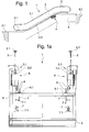
- Fig. 1 shows a side view of an escalator 1, the a first floor E1 connects to a second floor E2.
- the escalator 1 has a step consisting of Step band on.
- a handrail 2 with a flow 2.1 and a return 2.2 is arranged on a balustrade 3, at the bottom by means of a balustrade socket 3.1 is held.
- a arranged on the truss 5 Handrail drive 4 drives the handrail 2.
- Of the Balustrade base 3.1 is from a truss 5 of Escalator 1 worn.
- the escalator 1 is a comb plate arranged, the safe transition from the stationary part to the moving one Step band or from the moving step band on the fixed part of the escalator 1 guaranteed.
- Fig. 1a shows a cross section
- Fig. 1b shows a Section of escalator 1 with the in the balustrade base 3.1 arranged handrail drive 4, the handrail 2 in Rewind 2.2 drives.
- the step rollers 6 by means of guides 6.1 or the step rollers 7 by means Guides 7.1 are guided.
- a drift tire 4.1 of Handrail drive 4 is frictionally engaged with the outside 2.3 or the handrail cover of the Handrail 2.
- Press rollers 4.2 press the handrail 2 the inside 2.4 or on the sliding surface against the Drift tire 4.1, wherein each pressure roller 4.2 a Handrail 4.3 is provided, the handrail 2 on the end face 2.5 or leads to the handrail lip.
- Fig. 2 shows the handrail drive 4 from the drive side forth and Fig. 3 shows handrail drive 4 of the Drive wheel side ago.
- Connecting carrier 4.4 is an electric motor 4.5 and a transmission 4.6 arranged, wherein a Transmission sprocket 4.7 by means of a chain 4.8 with amaschineradkettenrad 4.9 is connected.
- a Transmission sprocket 4.7 by means of a chain 4.8 with amaschineradkettenrad 4.9
- the chain can also be a belt (Timing belt, V-belt) and pulleys should be provided.
- the Teibradkettenrad 4.9 can also from the stages moving step chain drive are driven.
- At the Carrier 4.4 is an axis 4.10 arranged at the one Rocker 4.11 is rotatably mounted with a boom 4.12.
- the rocker 4.11 serves as a carrier for the pressure rollers 4.2 and as a support for the handrail guides 4.3.
- a hanger 4.13 connects the boom 4.12 with the carrier 4.4, wherein the bracket 4.13 arranged in one of the carrier 4.4 Holes 4.14 engages.
- the pressure rollers 4.2 more or less against the Inside of the handrail 2 pressed.
- the Treibradkettenrad 4.9 stands by means of an axle 4.16 in conjunction with a Traction tire 4.1 carrying impeller 4.15, wherein the axis 4.16 is rotatably supported by a bearing 4.17.
- the one with a gas, such as compressed air filledmaschineradsammlung 4.1 is mounted on a demountable rim 4.18, the is arranged on the axis 4.16.
- the tire Tire 4.1 fits thanks to his Spring properties or air cushion properties of the mold of the handrail 2.
- a solid tire as a driving tire 4.1 is also possible.
- Fig. 5 shows a variant of the handrail drive 4.
- drive for the drive wheel 4.15 is instead of the Electric motor 4.5 and gear 4.6 a step 8 provided, the step-sprocket 8 on the axis 4.16 is arranged and is engaged with the step chain.
- the step chain drive driven step chain 9 consists of chain links 9.1, step rollers 6 and Stepped bolt 9.2, on which arranged the escalator steps are.
Landscapes
- Escalators And Moving Walkways (AREA)
Abstract
Description
eine Seitenansicht einer Fahrtreppe mit einem Handlaufantrieb,
einen Querschnitt der Fahrtreppe,
einen Ausschnitt des Fahrtreppensockels mit dem erfindungsgemässen Handlaufantrieb,
eine dreidimensionale Darstellung des erfindungsgemässen Handlaufantriebes von der Antriebsseite her gesehen,
eine dreidimensionale Darstellung des erfindungsgemässen Handlaufantriebes von der Treibradseite her gesehen,
einen Schnitt durch die Achse des Treibrades und
eine Ausführungsvariante des Handlaufantriebes.
Claims (6)
- Fahrtreppe (1) oder Fahrsteig bestehend aus einem Fachwerk (5), einem Stufenband mit Stufen bzw. Palettenband mit Paletten für den Transport von Personen und/oder Gegenständen und je Seite einer mittels eines Balustradensockels (3.1) gehaltenen Balustrade (3) mit Handlauf (2), wobei ein Handlaufantrieb (4) den Handlauf (2) antreibt,
dadurch gekennzeichnet, dass ein den Handlauf (2) auf der Aussenseite (2.3) antreibender Handlaufantrieb (4) vorgesehen ist. - Fahrtreppe (1) oder Fahrsteig nach Anspruch 1,
dadurch gekennzeichnet, dass der Handlaufantrieb (4) ein Treibrad (4.15) aufweist, das den Handlauf (2) an der Aussenseite (2.3) reibschlüssig antreibt, wobei handlaufinnenseitig angeordnete Anpressrollen (4.2) den Handlauf (2) gegen das Treibrad (4.15) drücken. - Fahrtreppe (1) oder Fahrsteig nach Anspruch 2,
dadurch gekennzeichnet, dass das Treibrad (4.15) einen Treibradreifen (4.1) aufweist, der den Handlauf (2) an der Aussenseite (2.3) reibschlüssig antreibt. - Fahrtreppe (1) oder Fahrsteig nach Anspruch 2,
dadurch gekennzeichnet, dass der Treibradreifen (4.1) an einer Felge (4.18) angeordnet ist, die in Verbindung steht mit einer Treibachse (4.16). - Fahrtreppe (1) oder Fahrsteig nach den Ansprüchen 3 oder 4,
dadurch gekennzeichnet, dass das Treibrad (4.15) mittels eines Motors (4.5) oder mittels eines Stufenkettenrades (8) oder mittels eines Stufenkettenantriebes antreibbar ist. - Fahrtreppe (1) oder Fahrsteig nach einem der Ansprüche 1 bis 5,
dadurch gekennzeichnet, dass die Anpressrollen (4.2) an einer Wippe (4.11) angeordnet sind, wobei mit der Stellung der Wippe (4.11) die Anpresskraft der Anpressrollen (4.2) einstellbar ist.
Priority Applications (1)
| Application Number | Priority Date | Filing Date | Title |
|---|---|---|---|
| EP20040007038 EP1464609B1 (de) | 2003-04-04 | 2004-03-24 | Handlaufantrieb für eine Fahrtreppe oder einen Fahrsteig |
Applications Claiming Priority (3)
| Application Number | Priority Date | Filing Date | Title |
|---|---|---|---|
| EP03405226 | 2003-04-04 | ||
| EP03405226 | 2003-04-04 | ||
| EP20040007038 EP1464609B1 (de) | 2003-04-04 | 2004-03-24 | Handlaufantrieb für eine Fahrtreppe oder einen Fahrsteig |
Publications (2)
| Publication Number | Publication Date |
|---|---|
| EP1464609A1 true EP1464609A1 (de) | 2004-10-06 |
| EP1464609B1 EP1464609B1 (de) | 2009-08-05 |
Family
ID=32852253
Family Applications (1)
| Application Number | Title | Priority Date | Filing Date |
|---|---|---|---|
| EP20040007038 Expired - Lifetime EP1464609B1 (de) | 2003-04-04 | 2004-03-24 | Handlaufantrieb für eine Fahrtreppe oder einen Fahrsteig |
Country Status (1)
| Country | Link |
|---|---|
| EP (1) | EP1464609B1 (de) |
Cited By (3)
| Publication number | Priority date | Publication date | Assignee | Title |
|---|---|---|---|---|
| EP1731471A1 (de) * | 2005-06-07 | 2006-12-13 | Inventio Ag | Rad zum Antreiben eines flexiblen Handlaufes |
| EP1731472A1 (de) * | 2005-06-07 | 2006-12-13 | Inventio Ag | Rad zum Antreiben eines flexiblen Handlaufs |
| CN1910106B (zh) * | 2004-01-22 | 2012-07-18 | 通力股份公司 | 活动人行道、活动坡道和扶梯 |
Citations (2)
| Publication number | Priority date | Publication date | Assignee | Title |
|---|---|---|---|---|
| CH404916A (de) * | 1963-11-06 | 1965-12-31 | Schweiz Wagons Aufzuegefab | Handlaufantrieb für Fahrtreppen und Fahrrampen |
| US6199678B1 (en) * | 1997-11-03 | 2001-03-13 | Lg Industrial Systems Co., Ltd. | Hand rail driving apparatus for escalator |
-
2004
- 2004-03-24 EP EP20040007038 patent/EP1464609B1/de not_active Expired - Lifetime
Patent Citations (2)
| Publication number | Priority date | Publication date | Assignee | Title |
|---|---|---|---|---|
| CH404916A (de) * | 1963-11-06 | 1965-12-31 | Schweiz Wagons Aufzuegefab | Handlaufantrieb für Fahrtreppen und Fahrrampen |
| US6199678B1 (en) * | 1997-11-03 | 2001-03-13 | Lg Industrial Systems Co., Ltd. | Hand rail driving apparatus for escalator |
Cited By (4)
| Publication number | Priority date | Publication date | Assignee | Title |
|---|---|---|---|---|
| CN1910106B (zh) * | 2004-01-22 | 2012-07-18 | 通力股份公司 | 活动人行道、活动坡道和扶梯 |
| EP1731471A1 (de) * | 2005-06-07 | 2006-12-13 | Inventio Ag | Rad zum Antreiben eines flexiblen Handlaufes |
| EP1731472A1 (de) * | 2005-06-07 | 2006-12-13 | Inventio Ag | Rad zum Antreiben eines flexiblen Handlaufs |
| KR101227791B1 (ko) * | 2005-06-07 | 2013-01-29 | 인벤티오 아게 | 가요성 핸드레일의 구동을 위한 휠 |
Also Published As
| Publication number | Publication date |
|---|---|
| EP1464609B1 (de) | 2009-08-05 |
Similar Documents
| Publication | Publication Date | Title |
|---|---|---|
| AU2001292771B2 (en) | Escalator drive machine with drive belts for simultaneously propelling handrail and conveyor surface | |
| EP1749786B1 (de) | Fahrtreppe | |
| DE102017006212A1 (de) | Antriebsvorrichtung, Antriebselement und Förderwagenantrieb | |
| EP0711725A1 (de) | Einrichtung zur Führung eines Bandkontinuums für Fahrtreppen oder Fahrsteige | |
| DE3437369A1 (de) | Bogenrolltreppe | |
| AU2007254612A1 (en) | Drive system with step chain or pallet chain for a transportation device and transporation device with a corresponding drive system | |
| EP1473259A1 (de) | Förderer zum Transportieren von Lastträgern | |
| AU2004201417B2 (en) | Handrail-drive for an escalator or a moving walk | |
| EP3224189A1 (de) | Handlaufantrieb für eine fahrtreppe oder einen fahrsteig | |
| EP1502891B1 (de) | Antriebseinrichtung für Fahrtreppenstufe oder Fahrsteigpalette | |
| EP1510477A1 (de) | Reibrollentrieb für auf Tragrollen verfahrbare Skids | |
| DE69419298T2 (de) | Trägervorrichtung für Stufenantriebskette einer Rolltreppe | |
| EP1502892A1 (de) | Antriebseinrichtung für Fahrtreppenstufe | |
| EP1464609B1 (de) | Handlaufantrieb für eine Fahrtreppe oder einen Fahrsteig | |
| DE69011156T2 (de) | Sich automatisch einstellender Antrieb für eine Halbleiste einer Fahrtreppe. | |
| DE3412350C2 (de) | Rollen innerhalb der Transportkette einer Personenfördereinrichtung | |
| EP0774403B1 (de) | Treppengängiges, motorisch angetriebenes Transportgerät | |
| EP1464608B1 (de) | Handlaufantrieb für eine Fahrtreppe oder einen Fahrsteig | |
| DE19856651A1 (de) | Vorrichtung zur Verhinderung übermäßigen Lärms in Stufenkettenrollen von Personenbeförderungsmitteln | |
| EP3665115A1 (de) | Handlauf-antriebssystem mit im handlauf integrierten antriebselementen | |
| WO2008122675A1 (de) | Beförderungsvorrichtung | |
| WO2008061492A1 (de) | Antrieb für aufzüge | |
| DE54860C (de) | Rollenlager mit endloser Rollenkette | |
| JP6881851B2 (ja) | 乗客コンベア | |
| EP1468954B1 (de) | Handlaufantrieb für fahrtreppe oder fahrsteig |
Legal Events
| Date | Code | Title | Description |
|---|---|---|---|
| PUAI | Public reference made under article 153(3) epc to a published international application that has entered the european phase |
Free format text: ORIGINAL CODE: 0009012 |
|
| AK | Designated contracting states |
Kind code of ref document: A1 Designated state(s): AT BE BG CH CY CZ DE DK EE ES FI FR GB GR HU IE IT LI LU MC NL PL PT RO SE SI SK TR |
|
| AX | Request for extension of the european patent |
Extension state: AL LT LV MK |
|
| 17P | Request for examination filed |
Effective date: 20050321 |
|
| REG | Reference to a national code |
Ref country code: HK Ref legal event code: DE Ref document number: 1069808 Country of ref document: HK |
|
| AKX | Designation fees paid |
Designated state(s): AT BE BG CH CY CZ DE DK EE ES FI FR GB GR HU IE IT LI LU MC NL PL PT RO SE SI SK TR |
|
| 17Q | First examination report despatched |
Effective date: 20070308 |
|
| GRAP | Despatch of communication of intention to grant a patent |
Free format text: ORIGINAL CODE: EPIDOSNIGR1 |
|
| GRAS | Grant fee paid |
Free format text: ORIGINAL CODE: EPIDOSNIGR3 |
|
| GRAA | (expected) grant |
Free format text: ORIGINAL CODE: 0009210 |
|
| AK | Designated contracting states |
Kind code of ref document: B1 Designated state(s): AT BE BG CH CY CZ DE DK EE ES FI FR GB GR HU IE IT LI LU MC NL PL PT RO SE SI SK TR |
|
| REG | Reference to a national code |
Ref country code: GB Ref legal event code: FG4D Free format text: NOT ENGLISH |
|
| REG | Reference to a national code |
Ref country code: CH Ref legal event code: EP |
|
| REG | Reference to a national code |
Ref country code: IE Ref legal event code: FG4D |
|
| REF | Corresponds to: |
Ref document number: 502004009846 Country of ref document: DE Date of ref document: 20090917 Kind code of ref document: P |
|
| REG | Reference to a national code |
Ref country code: HK Ref legal event code: GR Ref document number: 1069808 Country of ref document: HK |
|
| REG | Reference to a national code |
Ref country code: ES Ref legal event code: FG2A Ref document number: 2331242 Country of ref document: ES Kind code of ref document: T3 |
|
| PG25 | Lapsed in a contracting state [announced via postgrant information from national office to epo] |
Ref country code: SE Free format text: LAPSE BECAUSE OF FAILURE TO SUBMIT A TRANSLATION OF THE DESCRIPTION OR TO PAY THE FEE WITHIN THE PRESCRIBED TIME-LIMIT Effective date: 20090805 Ref country code: FI Free format text: LAPSE BECAUSE OF FAILURE TO SUBMIT A TRANSLATION OF THE DESCRIPTION OR TO PAY THE FEE WITHIN THE PRESCRIBED TIME-LIMIT Effective date: 20090805 |
|
| NLV1 | Nl: lapsed or annulled due to failure to fulfill the requirements of art. 29p and 29m of the patents act | ||
| PG25 | Lapsed in a contracting state [announced via postgrant information from national office to epo] |
Ref country code: PL Free format text: LAPSE BECAUSE OF FAILURE TO SUBMIT A TRANSLATION OF THE DESCRIPTION OR TO PAY THE FEE WITHIN THE PRESCRIBED TIME-LIMIT Effective date: 20090805 Ref country code: SI Free format text: LAPSE BECAUSE OF FAILURE TO SUBMIT A TRANSLATION OF THE DESCRIPTION OR TO PAY THE FEE WITHIN THE PRESCRIBED TIME-LIMIT Effective date: 20090805 Ref country code: NL Free format text: LAPSE BECAUSE OF FAILURE TO SUBMIT A TRANSLATION OF THE DESCRIPTION OR TO PAY THE FEE WITHIN THE PRESCRIBED TIME-LIMIT Effective date: 20090805 |
|
| REG | Reference to a national code |
Ref country code: IE Ref legal event code: FD4D |
|
| PG25 | Lapsed in a contracting state [announced via postgrant information from national office to epo] |
Ref country code: BG Free format text: LAPSE BECAUSE OF FAILURE TO SUBMIT A TRANSLATION OF THE DESCRIPTION OR TO PAY THE FEE WITHIN THE PRESCRIBED TIME-LIMIT Effective date: 20091105 Ref country code: PT Free format text: LAPSE BECAUSE OF FAILURE TO SUBMIT A TRANSLATION OF THE DESCRIPTION OR TO PAY THE FEE WITHIN THE PRESCRIBED TIME-LIMIT Effective date: 20091205 |
|
| PG25 | Lapsed in a contracting state [announced via postgrant information from national office to epo] |
Ref country code: CZ Free format text: LAPSE BECAUSE OF FAILURE TO SUBMIT A TRANSLATION OF THE DESCRIPTION OR TO PAY THE FEE WITHIN THE PRESCRIBED TIME-LIMIT Effective date: 20090805 Ref country code: DK Free format text: LAPSE BECAUSE OF FAILURE TO SUBMIT A TRANSLATION OF THE DESCRIPTION OR TO PAY THE FEE WITHIN THE PRESCRIBED TIME-LIMIT Effective date: 20090805 Ref country code: IE Free format text: LAPSE BECAUSE OF FAILURE TO SUBMIT A TRANSLATION OF THE DESCRIPTION OR TO PAY THE FEE WITHIN THE PRESCRIBED TIME-LIMIT Effective date: 20090805 Ref country code: EE Free format text: LAPSE BECAUSE OF FAILURE TO SUBMIT A TRANSLATION OF THE DESCRIPTION OR TO PAY THE FEE WITHIN THE PRESCRIBED TIME-LIMIT Effective date: 20090805 Ref country code: RO Free format text: LAPSE BECAUSE OF FAILURE TO SUBMIT A TRANSLATION OF THE DESCRIPTION OR TO PAY THE FEE WITHIN THE PRESCRIBED TIME-LIMIT Effective date: 20090805 |
|
| PG25 | Lapsed in a contracting state [announced via postgrant information from national office to epo] |
Ref country code: SK Free format text: LAPSE BECAUSE OF FAILURE TO SUBMIT A TRANSLATION OF THE DESCRIPTION OR TO PAY THE FEE WITHIN THE PRESCRIBED TIME-LIMIT Effective date: 20090805 |
|
| PLBE | No opposition filed within time limit |
Free format text: ORIGINAL CODE: 0009261 |
|
| STAA | Information on the status of an ep patent application or granted ep patent |
Free format text: STATUS: NO OPPOSITION FILED WITHIN TIME LIMIT |
|
| 26N | No opposition filed |
Effective date: 20100507 |
|
| BERE | Be: lapsed |
Owner name: INVENTIO A.G. Effective date: 20100331 |
|
| PG25 | Lapsed in a contracting state [announced via postgrant information from national office to epo] |
Ref country code: MC Free format text: LAPSE BECAUSE OF NON-PAYMENT OF DUE FEES Effective date: 20100331 Ref country code: GR Free format text: LAPSE BECAUSE OF FAILURE TO SUBMIT A TRANSLATION OF THE DESCRIPTION OR TO PAY THE FEE WITHIN THE PRESCRIBED TIME-LIMIT Effective date: 20091106 |
|
| PG25 | Lapsed in a contracting state [announced via postgrant information from national office to epo] |
Ref country code: BE Free format text: LAPSE BECAUSE OF NON-PAYMENT OF DUE FEES Effective date: 20100331 |
|
| PG25 | Lapsed in a contracting state [announced via postgrant information from national office to epo] |
Ref country code: AT Free format text: LAPSE BECAUSE OF NON-PAYMENT OF DUE FEES Effective date: 20100324 |
|
| PG25 | Lapsed in a contracting state [announced via postgrant information from national office to epo] |
Ref country code: CY Free format text: LAPSE BECAUSE OF FAILURE TO SUBMIT A TRANSLATION OF THE DESCRIPTION OR TO PAY THE FEE WITHIN THE PRESCRIBED TIME-LIMIT Effective date: 20090805 |
|
| PG25 | Lapsed in a contracting state [announced via postgrant information from national office to epo] |
Ref country code: LU Free format text: LAPSE BECAUSE OF NON-PAYMENT OF DUE FEES Effective date: 20100324 Ref country code: HU Free format text: LAPSE BECAUSE OF FAILURE TO SUBMIT A TRANSLATION OF THE DESCRIPTION OR TO PAY THE FEE WITHIN THE PRESCRIBED TIME-LIMIT Effective date: 20100206 |
|
| PG25 | Lapsed in a contracting state [announced via postgrant information from national office to epo] |
Ref country code: TR Free format text: LAPSE BECAUSE OF FAILURE TO SUBMIT A TRANSLATION OF THE DESCRIPTION OR TO PAY THE FEE WITHIN THE PRESCRIBED TIME-LIMIT Effective date: 20090805 |
|
| REG | Reference to a national code |
Ref country code: FR Ref legal event code: PLFP Year of fee payment: 13 |
|
| REG | Reference to a national code |
Ref country code: FR Ref legal event code: PLFP Year of fee payment: 14 |
|
| PGFP | Annual fee paid to national office [announced via postgrant information from national office to epo] |
Ref country code: CH Payment date: 20170329 Year of fee payment: 14 |
|
| PGFP | Annual fee paid to national office [announced via postgrant information from national office to epo] |
Ref country code: ES Payment date: 20170315 Year of fee payment: 14 |
|
| REG | Reference to a national code |
Ref country code: FR Ref legal event code: PLFP Year of fee payment: 15 |
|
| REG | Reference to a national code |
Ref country code: CH Ref legal event code: PL |
|
| PG25 | Lapsed in a contracting state [announced via postgrant information from national office to epo] |
Ref country code: CH Free format text: LAPSE BECAUSE OF NON-PAYMENT OF DUE FEES Effective date: 20180331 Ref country code: LI Free format text: LAPSE BECAUSE OF NON-PAYMENT OF DUE FEES Effective date: 20180331 |
|
| PGFP | Annual fee paid to national office [announced via postgrant information from national office to epo] |
Ref country code: GB Payment date: 20190320 Year of fee payment: 16 Ref country code: FR Payment date: 20190322 Year of fee payment: 16 Ref country code: IT Payment date: 20190325 Year of fee payment: 16 Ref country code: DE Payment date: 20190321 Year of fee payment: 16 |
|
| REG | Reference to a national code |
Ref country code: ES Ref legal event code: FD2A Effective date: 20190911 |
|
| PG25 | Lapsed in a contracting state [announced via postgrant information from national office to epo] |
Ref country code: ES Free format text: LAPSE BECAUSE OF NON-PAYMENT OF DUE FEES Effective date: 20180325 |
|
| REG | Reference to a national code |
Ref country code: DE Ref legal event code: R119 Ref document number: 502004009846 Country of ref document: DE |
|
| PG25 | Lapsed in a contracting state [announced via postgrant information from national office to epo] |
Ref country code: DE Free format text: LAPSE BECAUSE OF NON-PAYMENT OF DUE FEES Effective date: 20201001 Ref country code: FR Free format text: LAPSE BECAUSE OF NON-PAYMENT OF DUE FEES Effective date: 20200331 |
|
| GBPC | Gb: european patent ceased through non-payment of renewal fee |
Effective date: 20200324 |
|
| PG25 | Lapsed in a contracting state [announced via postgrant information from national office to epo] |
Ref country code: GB Free format text: LAPSE BECAUSE OF NON-PAYMENT OF DUE FEES Effective date: 20200324 |
|
| PG25 | Lapsed in a contracting state [announced via postgrant information from national office to epo] |
Ref country code: IT Free format text: LAPSE BECAUSE OF NON-PAYMENT OF DUE FEES Effective date: 20200324 |