EP1463156A2 - Stabilisation de contact au moyen d' un composant de renforcement de verroulage première - Google Patents
Stabilisation de contact au moyen d' un composant de renforcement de verroulage première Download PDFInfo
- Publication number
- EP1463156A2 EP1463156A2 EP04251685A EP04251685A EP1463156A2 EP 1463156 A2 EP1463156 A2 EP 1463156A2 EP 04251685 A EP04251685 A EP 04251685A EP 04251685 A EP04251685 A EP 04251685A EP 1463156 A2 EP1463156 A2 EP 1463156A2
- Authority
- EP
- European Patent Office
- Prior art keywords
- contact member
- fingers
- housing
- housing unit
- stabilization device
- Prior art date
- Legal status (The legal status is an assumption and is not a legal conclusion. Google has not performed a legal analysis and makes no representation as to the accuracy of the status listed.)
- Withdrawn
Links
Images


Classifications
-
- H—ELECTRICITY
- H01—ELECTRIC ELEMENTS
- H01R—ELECTRICALLY-CONDUCTIVE CONNECTIONS; STRUCTURAL ASSOCIATIONS OF A PLURALITY OF MUTUALLY-INSULATED ELECTRICAL CONNECTING ELEMENTS; COUPLING DEVICES; CURRENT COLLECTORS
- H01R13/00—Details of coupling devices of the kinds covered by groups H01R12/70 or H01R24/00 - H01R33/00
- H01R13/40—Securing contact members in or to a base or case; Insulating of contact members
- H01R13/42—Securing in a demountable manner
- H01R13/436—Securing a plurality of contact members by one locking piece or operation
- H01R13/4364—Insertion of locking piece from the front
-
- H—ELECTRICITY
- H01—ELECTRIC ELEMENTS
- H01R—ELECTRICALLY-CONDUCTIVE CONNECTIONS; STRUCTURAL ASSOCIATIONS OF A PLURALITY OF MUTUALLY-INSULATED ELECTRICAL CONNECTING ELEMENTS; COUPLING DEVICES; CURRENT COLLECTORS
- H01R13/00—Details of coupling devices of the kinds covered by groups H01R12/70 or H01R24/00 - H01R33/00
- H01R13/40—Securing contact members in or to a base or case; Insulating of contact members
- H01R13/42—Securing in a demountable manner
- H01R13/422—Securing in resilient one-piece base or case, e.g. by friction; One-piece base or case formed with resilient locking means
- H01R13/4223—Securing in resilient one-piece base or case, e.g. by friction; One-piece base or case formed with resilient locking means comprising integral flexible contact retaining fingers
Definitions
- the invention generally relates to contact stabilization mechanisms used in electrical connector assemblies, and more particularly to a stabilization alignment mechanism utilizing primary latching reinforcement operable in an electrical connector assembly.
- Another problem with the conventional stabilization devices is that it is difficult to determine if the internal components and contact members, themselves, have been fully seated within the connector housings, especially after the housings have been sealed.
- a terminal position assurance (TPA) member such as a wedge-shaped structure, may be pre-mounted on a surface of a housing. This member then pushes the internal electrical components and terminals to fully seat them with respect to the remainder of the connector housing, and then snaps into place.
- TPA terminal position assurance
- TPA member may include an insertable comb.
- the TPA comb is installed after the terminals have been inserted into the connector body and, usually, the TPA comb engages a shoulder of the terminal to interferingly prevent withdrawal of the terminals from the housing. Insertion of the comb may also be used to push the contacts forward into position.
- a stabilization alignment device primary latching reinforcement assurance and operable in an electrical connector assembly, wherein the device comprises a first housing unit having an outer wall configured along an outer perimeter of the first housing unit, a contact member extending outwardly from a base surface of the first housing unit, a plurality of fingers protruding from the base surface of the first housing unit, wherein the fingers are arranged parallel to each longitudinal side of the contact member, and a support receptacle positioned on the second housing unit to cradle the contact member.
- the second housing unit preferably includes a support wall, wherein the support wall has a notch thereon, and wherein the notch comprises a back portion having an inner surface and an outer surface.
- a protrusion on the first housing unit engages the outer surface of the back portion of the notch to ensure proper alignment of the connector.
- the contact member is preferably configured along a central axis of the first housing unit, and the support comprises a generally elongated central shaft having a plurality of engagement members aligned along each longitudinal side of the central shaft.
- the first housing unit further comprises a plurality of holes in the base surface, wherein the holes are dimensioned and configured to receive the terminal pins.
- the second housing unit further comprises a plurality of wedge members, wherein the wedge members are dimensioned and configured to engage the fingers.
- the fingers comprise a step positioned on an edge of an upper surface of the fingers, wherein the second housing unit comprises a plurality of mounting tabs dimensioned and configured to engage the step on the fingers.
- Embodiments of the invention overcome the several disadvantages of the conventional designs, and in particular, have an advantage over conventional stabilization alignment devices because movement of the contact member in the electrical connector assembly system is limited. Another advantage is that primary latching reinforcement position assurance is utilized to further its stabilization of internal device components. Still another advantage is that damage to internal assembly components during vibration is arrested and/or limited.
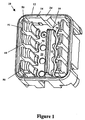
- Figure 1 is a perspective view of a contact stabilization alignment device according to an embodiment of the invention.
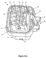
- Figures 2(a)-(b) are perspective views of a contact stabilization alignment device according to an embodiment of the invention.
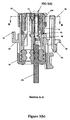
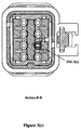
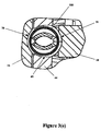
- Figures 3(a)-(e) are views of an assembled contact stabilization alignment device shown in a closed position.
- Embodiments of the invention provide a stabilization alignment device used in electrical connector assemblies that utilizes contact position assurance, and which limits damage to internal assembly components during periods of vibration.
- FIG. 1 a first housing unit is illustrated in Figure 1
- FIG. 2(a)-(b) a second housing unit in Figures 2(a)-(b)
- a complete stabilization alignment device utilizing primary latching reinforcement operable in an electrical connector assembly is illustrated in detail in Figures 3(a)-(e).
- the device comprises a generally rectangular first housing unit 10, which is the upper housing unit of the assembly 1 ( Figure 3(a)), wherein the first housing unit 10 preferably comprises an outer wall 14 with an outer lip 12 configured along an outer perimeter of the first housing unit 10.
- the device also preferably includes a generally elongated contact member 16 extending outwardly from a base surface 21 of the first housing unit 10, a plurality of primary locking fingers 18 protruding from the base surface 21 of the first housing unit 10, wherein the primary locking fingers 18 are arranged parallel and proximate to each longitudinal side 22 of the contact member 16.
- the primary locking fingers 18 preferably include a generally curvilinear base portion 75 extending up the primary locking finger 18.
- contact member 16 preferably includes a plurality of curvilinear cutout portions 70 aligned on each longitudinal side 22 of the contact member 16.
- the contact member 16 preferably has a generally beveled upper surface and is located along the central axis of the upper housing unit 10.
- the second housing unit 20 shown in Figure 2(a)-(b), represents the lower housing unit of the assembly 1.
- Second housing unit 20 preferably includes a support receptacle 32 positioned along the central axis of the second housing unit 20 to cradle the contact member 16 upon mating.
- Support 32 preferably comprises a generally elongated central shaft member 42 having a plurality of engagement members 44, having curved sidewalls 45, aligned along each longitudinal side 46 of the central shaft 42.
- the first housing unit 10 further comprises a plurality of holes 26 in the base surface 21 (Figure 1), wherein the holes 26 are dimensioned and configured to be aligned with terminal contacts 100 when they are inserted into the housings ( Figure 3).
- engagement members 44 fit between primary locking fingers 18 and against contact member 16 so that the curved sidewalls 45 of engagement members 44, curvilinear base portion 75, and curvilinear cutout portions 70 form a receptacle for receiving terminal contacts 100 ( Figure 3), assuring that the terminal contacts are properly positioned and secured against excessive vibration.
- the device also preferably includes a polarization feature to ensure proper alignment of the first and second housing.
- a protrusion 24 may extend inwardly from the outer wall 14 and extend upwardly from the base surface 21 of first housing unit 10 ( Figure 1). While protrusion 24 is shown herein as generally wedged-shaped, it is not limited thereto.
- the second housing unit 20 further preferably comprises a support wall 34 extending around an upper portion 74 of the second housing unit 20, wherein the support wall 34 includes a notch 28, and wherein the notch 28, in this embodiment, comprises a back portion 36 having an inner surface 40, a notch base surface 78, and an inner surface 38.
- protrusion 24 engages both the notch base surface 78 and the inner surface 38 of the back portion 36 of the notch 28.
- Protrusion 24 ensures proper alignment and mating of the upper housing 10 with the lower housing 20 by only allowing the units to be coupled in one configuration.
- the second housing unit 20 may further comprise a plurality of latch finger or wedge members 48, wherein the latch finger members 48 are dimensioned and configured to engage the primary locking fingers 18 of the first housing unit 10, in the manner shown in Figure 3(b).
- Primary locking fingers 18 are preferably positioned one adjacent to another, wherein each of the four end primary locking fingers 18 preferably include a step 50 positioned on an edge of an upper surface 51 of the primary locking fingers 18 ( Figure 1), wherein the second housing unit 20 comprises a plurality of mounting tabs 52 dimensioned and configured to engage the step 50 of the respective primary locking fingers 18 ( Figures 2(a)-(b)).
- the second housing unit 20 further preferably comprises a lower portion 76, locking latch 58, which includes a catch 62. Additionally, mounting flange 54 extends upwardly from said second housing unit 20, and is positioned as shown. Moreover, a locking latch 58 with a delatching pad 56 is preferably provided on the second housing unit 20, which includes a pair of over stress devices 60 for mounting in a vehicle or to another assembly.
- Figure 3(a) illustrates the assembly 1 once the upper housing unit 10 is aligned and mated with the lower housing unit 20. End cap 30 may also be included, through which conductor 104 passes.
- the internal components of both the upper housing unit 10 and lower housing unit 20, particularly the contact member 16, are shown fully engaged, aligned, and stabilized in Figure 3(b).
- the assembly 1 shown in Figures 3(a)-(e) limits excessive movement using the support receptacle 32 as a cradle for the contact member 16. This cradling effect along with primary locking fingers 18, and contact member 16 allows for proper control of terminal contacts 100 and 104, which are secured into position.
- latch finger members 48 are forced against the lower portion of terminal contacts 100 by upper surface 51 of primary locking fingers 18 to provide a primary latching reinforcement (PLR) of terminal contacts 100 within the connector assembly.
- PLR primary latching reinforcement
- Embodiments of the invention overcome the several disadvantages of the conventional designs, and in particular, has an advantage over conventional stabilization alignment devices because of utilizing a novel design which limits the movement of the contact member in the electrical connector assembly system.
- Another advantage of embodiments of the invention is that it utilizes primary latching reinforcement to further its stabilization of internal device components.
- Still another advantage of embodiments of the invention is that it prevents damage to internal assembly components during vibration.
Landscapes
- Connector Housings Or Holding Contact Members (AREA)
Applications Claiming Priority (2)
| Application Number | Priority Date | Filing Date | Title |
|---|---|---|---|
| US10/396,840 US20040192108A1 (en) | 2003-03-25 | 2003-03-25 | Contact stabilization by means of a primary latch reinforcement component |
| US396840 | 2003-03-25 |
Publications (1)
| Publication Number | Publication Date |
|---|---|
| EP1463156A2 true EP1463156A2 (fr) | 2004-09-29 |
Family
ID=32824961
Family Applications (1)
| Application Number | Title | Priority Date | Filing Date |
|---|---|---|---|
| EP04251685A Withdrawn EP1463156A2 (fr) | 2003-03-25 | 2004-03-24 | Stabilisation de contact au moyen d' un composant de renforcement de verroulage première |
Country Status (3)
| Country | Link |
|---|---|
| US (1) | US20040192108A1 (fr) |
| EP (1) | EP1463156A2 (fr) |
| JP (1) | JP2004296439A (fr) |
Cited By (1)
| Publication number | Priority date | Publication date | Assignee | Title |
|---|---|---|---|---|
| EP1833122A2 (fr) | 2006-03-07 | 2007-09-12 | Delphi Technologies, Inc. | Boîtier de terminal de connecteur électrique |
Families Citing this family (11)
| Publication number | Priority date | Publication date | Assignee | Title |
|---|---|---|---|---|
| JP4554376B2 (ja) * | 2005-01-14 | 2010-09-29 | 矢崎総業株式会社 | コネクタ |
| KR100731253B1 (ko) | 2005-03-30 | 2007-06-21 | 한국몰렉스 주식회사 | 암커넥터 조립체 |
| JP2006302752A (ja) * | 2005-04-22 | 2006-11-02 | Tyco Electronics Amp Kk | 電気コネクタ |
| US7278883B2 (en) * | 2005-09-26 | 2007-10-09 | Fci Americas Technology, Inc. | Electrical connector housing with terminal position assurance (TPA) member |
| JP2010027429A (ja) * | 2008-07-22 | 2010-02-04 | Fujifilm Corp | 有機電界発光パネル及びその製造方法 |
| CN102938516B (zh) * | 2012-10-18 | 2016-03-02 | 中航光电科技股份有限公司 | 接触件可取卸的电连接器 |
| US9419392B2 (en) * | 2014-07-09 | 2016-08-16 | Verizon Telematics Inc. | Automatic identification of an adapter in an on-board diagnostic system |
| CN109119786B (zh) * | 2017-06-23 | 2020-11-06 | 上海电巴新能源科技有限公司 | 低压极柱及包含其的电连接器 |
| CN111446592B (zh) * | 2019-01-17 | 2021-11-16 | 泰科电子(上海)有限公司 | 连接器壳体和电连接器 |
| DE102019113494A1 (de) | 2019-05-21 | 2020-11-26 | Harting Electric Gmbh & Co. Kg | Kontaktträger |
| US20230411892A1 (en) * | 2022-06-21 | 2023-12-21 | Aptiv Technologies Limited | Electrical connector assembly with flexible and rigid terminal locking features |
Family Cites Families (3)
| Publication number | Priority date | Publication date | Assignee | Title |
|---|---|---|---|---|
| JPH076809A (ja) * | 1993-06-18 | 1995-01-10 | Yazaki Corp | 端子係止具付きコネクタ |
| JP3454709B2 (ja) * | 1998-04-07 | 2003-10-06 | 矢崎総業株式会社 | 圧接コネクタ |
| US6106340A (en) * | 1998-04-30 | 2000-08-22 | The Whitaker Corporation | Electrical connector with deflectable secondary |
-
2003
- 2003-03-25 US US10/396,840 patent/US20040192108A1/en not_active Abandoned
-
2004
- 2004-03-19 JP JP2004079617A patent/JP2004296439A/ja active Pending
- 2004-03-24 EP EP04251685A patent/EP1463156A2/fr not_active Withdrawn
Cited By (2)
| Publication number | Priority date | Publication date | Assignee | Title |
|---|---|---|---|---|
| EP1833122A2 (fr) | 2006-03-07 | 2007-09-12 | Delphi Technologies, Inc. | Boîtier de terminal de connecteur électrique |
| EP1833122A3 (fr) * | 2006-03-07 | 2008-12-24 | Delphi Technologies, Inc. | Boîtier de terminal de connecteur électrique |
Also Published As
| Publication number | Publication date |
|---|---|
| US20040192108A1 (en) | 2004-09-30 |
| JP2004296439A (ja) | 2004-10-21 |
Similar Documents
| Publication | Publication Date | Title |
|---|---|---|
| KR100501561B1 (ko) | 전기 터미널용 카울 커넥터 | |
| US9325114B2 (en) | Plug connector | |
| US5653606A (en) | Electrical interconnection system having retention and shorting features | |
| JP2622888B2 (ja) | 電気コネクタ | |
| EP1882287B1 (fr) | Connecteur électrique avec mécanisme de verrouillage | |
| EP1463156A2 (fr) | Stabilisation de contact au moyen d' un composant de renforcement de verroulage première | |
| EP0706237B1 (fr) | Connecteur électrique avec dispositif à assurer la position des terminaux et moyens de guidage d'un connecteur complémentaire | |
| US5520548A (en) | Vibration proof electrical connector housing | |
| US9843132B2 (en) | Cable strain relief | |
| EP0632536B1 (fr) | Boítier de connecteur électrique résistant aux vibrations | |
| US20020043876A1 (en) | Electrical connection box for a vehicle | |
| JP2018521485A (ja) | 耐振動性の短絡ブリッジを有する電気プラグコネクタおよび電気プラグ接続 | |
| US7172459B2 (en) | Electrical connector housing, electrical connector, and connector assembly | |
| EP0585646A1 (fr) | Dispositif de retenue de faible hauteur montable sur un panneau pour connecter électrique | |
| CA2242029C (fr) | Connecteur enfichable a profil mince | |
| CN100530845C (zh) | 触发系统的接插件和短路组件 | |
| US6034584A (en) | Arrangement for mechanically coupling an overload relay to a contactor | |
| US6648700B1 (en) | Stepped/keying interface stabilization alignment mechanism | |
| US6666730B2 (en) | Electric connector, with contact positioning elements | |
| US6609930B2 (en) | Electric connector | |
| EP0700127A2 (fr) | Dispositif de connecteur de shuntage | |
| EP3716413A1 (fr) | Connecteur | |
| KR102612492B1 (ko) | 잠금 스프링을 갖는 전기 커넥터 | |
| KR200486277Y1 (ko) | 도어 커넥터 | |
| CN114792902A (zh) | 具有无端子连接系统的电连接器组件 |
Legal Events
| Date | Code | Title | Description |
|---|---|---|---|
| PUAI | Public reference made under article 153(3) epc to a published international application that has entered the european phase |
Free format text: ORIGINAL CODE: 0009012 |
|
| AK | Designated contracting states |
Kind code of ref document: A2 Designated state(s): AT BE BG CH CY CZ DE DK EE ES FI FR GB GR HU IE IT LI LU MC NL PL PT RO SE SI SK TR |
|
| AX | Request for extension of the european patent |
Extension state: AL HR LT LV MK |
|
| STAA | Information on the status of an ep patent application or granted ep patent |
Free format text: STATUS: THE APPLICATION HAS BEEN WITHDRAWN |
|
| 18W | Application withdrawn |
Effective date: 20041108 |