EP1458043A1 - Brennstoffzelle und Methode zu deren Herstellung - Google Patents
Brennstoffzelle und Methode zu deren Herstellung Download PDFInfo
- Publication number
- EP1458043A1 EP1458043A1 EP04251437A EP04251437A EP1458043A1 EP 1458043 A1 EP1458043 A1 EP 1458043A1 EP 04251437 A EP04251437 A EP 04251437A EP 04251437 A EP04251437 A EP 04251437A EP 1458043 A1 EP1458043 A1 EP 1458043A1
- Authority
- EP
- European Patent Office
- Prior art keywords
- layer
- fuel cell
- edge
- disposing
- substrate
- Prior art date
- Legal status (The legal status is an assumption and is not a legal conclusion. Google has not performed a legal analysis and makes no representation as to the accuracy of the status listed.)
- Withdrawn
Links
Images

Classifications
-
- H—ELECTRICITY
- H01—ELECTRIC ELEMENTS
- H01M—PROCESSES OR MEANS, e.g. BATTERIES, FOR THE DIRECT CONVERSION OF CHEMICAL ENERGY INTO ELECTRICAL ENERGY
- H01M8/00—Fuel cells; Manufacture thereof
- H01M8/02—Details
- H01M8/0271—Sealing or supporting means around electrodes, matrices or membranes
- H01M8/028—Sealing means characterised by their material
- H01M8/0282—Inorganic material
-
- H—ELECTRICITY
- H01—ELECTRIC ELEMENTS
- H01M—PROCESSES OR MEANS, e.g. BATTERIES, FOR THE DIRECT CONVERSION OF CHEMICAL ENERGY INTO ELECTRICAL ENERGY
- H01M8/00—Fuel cells; Manufacture thereof
- H01M8/02—Details
- H01M8/0271—Sealing or supporting means around electrodes, matrices or membranes
- H01M8/0286—Processes for forming seals
-
- H—ELECTRICITY
- H01—ELECTRIC ELEMENTS
- H01M—PROCESSES OR MEANS, e.g. BATTERIES, FOR THE DIRECT CONVERSION OF CHEMICAL ENERGY INTO ELECTRICAL ENERGY
- H01M8/00—Fuel cells; Manufacture thereof
- H01M8/10—Fuel cells with solid electrolytes
- H01M8/12—Fuel cells with solid electrolytes operating at high temperature, e.g. with stabilised ZrO2 electrolyte
- H01M8/1213—Fuel cells with solid electrolytes operating at high temperature, e.g. with stabilised ZrO2 electrolyte characterised by the electrode/electrolyte combination or the supporting material
-
- H—ELECTRICITY
- H01—ELECTRIC ELEMENTS
- H01M—PROCESSES OR MEANS, e.g. BATTERIES, FOR THE DIRECT CONVERSION OF CHEMICAL ENERGY INTO ELECTRICAL ENERGY
- H01M8/00—Fuel cells; Manufacture thereof
- H01M8/24—Grouping of fuel cells, e.g. stacking of fuel cells
- H01M8/2404—Processes or apparatus for grouping fuel cells
-
- H—ELECTRICITY
- H01—ELECTRIC ELEMENTS
- H01M—PROCESSES OR MEANS, e.g. BATTERIES, FOR THE DIRECT CONVERSION OF CHEMICAL ENERGY INTO ELECTRICAL ENERGY
- H01M8/00—Fuel cells; Manufacture thereof
- H01M8/24—Grouping of fuel cells, e.g. stacking of fuel cells
- H01M8/241—Grouping of fuel cells, e.g. stacking of fuel cells with solid or matrix-supported electrolytes
- H01M8/2425—High-temperature cells with solid electrolytes
- H01M8/2432—Grouping of unit cells of planar configuration
-
- H—ELECTRICITY
- H01—ELECTRIC ELEMENTS
- H01M—PROCESSES OR MEANS, e.g. BATTERIES, FOR THE DIRECT CONVERSION OF CHEMICAL ENERGY INTO ELECTRICAL ENERGY
- H01M8/00—Fuel cells; Manufacture thereof
- H01M8/10—Fuel cells with solid electrolytes
- H01M8/12—Fuel cells with solid electrolytes operating at high temperature, e.g. with stabilised ZrO2 electrolyte
- H01M8/124—Fuel cells with solid electrolytes operating at high temperature, e.g. with stabilised ZrO2 electrolyte characterised by the process of manufacturing or by the material of the electrolyte
-
- Y—GENERAL TAGGING OF NEW TECHNOLOGICAL DEVELOPMENTS; GENERAL TAGGING OF CROSS-SECTIONAL TECHNOLOGIES SPANNING OVER SEVERAL SECTIONS OF THE IPC; TECHNICAL SUBJECTS COVERED BY FORMER USPC CROSS-REFERENCE ART COLLECTIONS [XRACs] AND DIGESTS
- Y02—TECHNOLOGIES OR APPLICATIONS FOR MITIGATION OR ADAPTATION AGAINST CLIMATE CHANGE
- Y02E—REDUCTION OF GREENHOUSE GAS [GHG] EMISSIONS, RELATED TO ENERGY GENERATION, TRANSMISSION OR DISTRIBUTION
- Y02E60/00—Enabling technologies; Technologies with a potential or indirect contribution to GHG emissions mitigation
- Y02E60/30—Hydrogen technology
- Y02E60/50—Fuel cells
-
- Y—GENERAL TAGGING OF NEW TECHNOLOGICAL DEVELOPMENTS; GENERAL TAGGING OF CROSS-SECTIONAL TECHNOLOGIES SPANNING OVER SEVERAL SECTIONS OF THE IPC; TECHNICAL SUBJECTS COVERED BY FORMER USPC CROSS-REFERENCE ART COLLECTIONS [XRACs] AND DIGESTS
- Y02—TECHNOLOGIES OR APPLICATIONS FOR MITIGATION OR ADAPTATION AGAINST CLIMATE CHANGE
- Y02P—CLIMATE CHANGE MITIGATION TECHNOLOGIES IN THE PRODUCTION OR PROCESSING OF GOODS
- Y02P70/00—Climate change mitigation technologies in the production process for final industrial or consumer products
- Y02P70/50—Manufacturing or production processes characterised by the final manufactured product
Definitions
- This invention relates to solid oxide fuel cells. More particularly, this invention relates to methods for manufacturing solid oxide fuel cells. This invention also relates to fuel cells manufactured by such methods.
- Solid oxide fuel cells in part comprise a solid electrolyte layer interposed between two electrodes, the electrodes comprising an anode and a cathode.
- the electrolyte layer is usually dense so as to be impermeable to gas flow and comprises a material that is an electron insulator and an ion conductor, such as, for example, stabilized zirconia.
- the electrolyte layer is also generally desired to be as thin as possible to minimize resistance to ionic conduction within the electrolyte layer.
- both the anode and the cathode comprise pores to allow flow of gas within each electrode in order to maintain a local environment suitable for the electrochemical reactions taking place therein.
- the cathode usually comprises a ceramic material that is doped for high electrical conductivity, such as strontium-doped lanthanum manganite (also referred to herein as lanthanum strontium manganite), and is maintained in an oxidizing atmosphere, such as air or other gas comprising oxygen.
- the anode usually comprises a mixture of a metal with a ceramic, such as nickel with stabilized zirconia, and is maintained in a reducing atmosphere (referred to herein as the "fuel gas”), such as a gas comprising hydrogen.
- Interconnection plates also referred to herein as "interconnects,” often electrically connect several anode-electrolyte-cathode units (hereinafter referred to as "fuel cell units") with one another to form a fuel cell.
- SOFC electrodes and electrolyte layers are typically manufactured using conventional ceramic fabrication methods, such as tape casting, tape calendaring, coat-mix processes, and screen-printing.
- conventional ceramic fabrication methods such as tape casting, tape calendaring, coat-mix processes, and screen-printing.
- One embodiment is a method for manufacturing a fuel cell assembly.
- the method comprises providing at least one substrate; and disposing a plurality of fuel cell component layers on the substrate by at least one physical vapor deposition process. Each layer of the plurality comprises an edge bordering the layer.
- a second embodiment is a fuel cell assembly comprising at least one unit.
- the unit comprises at least one substrate; a plurality of fuel cell component layers disposed on the substrate, wherein each layer of the plurality comprises an edge bordering the layer; and at least one dense layer of material disposed over at least a portion of the edge of at least one fuel cell component layer.
- the at least one dense layer seals at least the aforementioned portion of the edge.
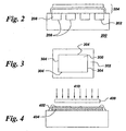
- a typical planar fuel cell unit 100 comprises a stack of component layers, where the stack comprises a dense electrolyte 102 layer interposed between, and in contact with, a porous anode 104 layer and a porous cathode 106 layer.
- the stack is often attached to a metallic interconnect 108, which often comprises channels 110 disposed to allow the flow of two distinct gas streams.
- the gas stream flowing in channels 110 adjacent to cathode 106 is the oxidizing gas
- the gas stream flowing in channels adjacent to anode 104 is the fuel gas, as described above.
- the fuel gas and oxidizing gas flow paths are generally kept separate throughout the cell, including at both the inlet and the exhaust of the fuel cell.
- the electrolyte 102 and interconnect 108 layers generally are sufficiently dense to hermetically seal the flows within the bulk of the fuel cell unit, but edges of the stack need to have dense seals 112 applied to avoid leakage out the sides of the stack.
- gas is typically delivered through a manifold (not shown).
- the manifold may be external to the fuel cell units 100 or internal to the units 100, but in either case, seals are needed to keep fuel gas from contacting the cathode and to keep the oxidizing gas from contacting the anode. Oxidation of the anode is a particularly undesirable situation, as it can lead to expansion stresses and failure of the fuel cell.
- the power output of the fuel cell directly relates to the size and number of fuel cell units 100 assembled into a fuel cell, and so maximizing the size or number of fuel cell units 100 in the fuel cell is desirable.
- maximizing the size or number of fuel cell units 100 in the fuel cell is desirable.
- achieving effective sealing at layer edges and manifold interfaces by conventional means becomes increasingly difficult.
- Embodiments of the present invention include a method for manufacturing a fuel cell assembly.
- the method comprises providing at least one substrate 202; and disposing a plurality of fuel cell component layers 204 on the substrate by at least one physical vapor deposition process.
- Figure 3 presents a top view of a typical fuel cell component layer 300 disposed on a substrate 302 in accordance with embodiments of the present invention.
- Each layer 300 disposed on substrate 302 comprises an edge 304 bordering layer 300, that is, edge 304 defines the perimeter of layer 300 as viewed from the top as in Figure 3.
- substrate 302 and layer 300 are depicted in Figure 3 as rectangular in shape is not to be construed to limit embodiments of the invention in any way, as those skilled in the art will appreciate that both substrate 302 and layer 300 may be processed into any of a variety of shapes.
- providing the at least one substrate 202 comprises providing at least one of an interconnect, an anode, and a cathode.
- substrate 202 is selected in part to provide mechanical support for the fuel cell unit 200.
- electrode-supported is used in the art to describe a fuel cell unit 200 in which either of the two electrode layers, namely the anode and the cathode, serves as the supportive substrate, while the term “interconnect-supported” is used herein to describe a fuel cell unit 200 in which the interconnect provides the support function.
- providing substrate 202 comprises providing a substrate 202 comprising sacrificial material 206.
- This sacrificial material 206 is typically used in embodiments where internal channels 208 are desired to be disposed within a fuel cell unit 200. Such internal channels 208 are typically used to allow oxidizing gas and fuel gas to flow within the fuel cell unit 200.
- the exemplary, non-limiting embodiment illustrated in Figure 2 shows an interconnect-supported fuel cell unit 200 in which channels 208 have been disposed by machining or other method of creating a patterned surface. Sacrificial material 206 is disposed within channels 208 prior to disposing the plurality of fuel cell component layers 204. In this way, sacrificial material 206 serves to create a planar surface upon which layers 204 may be disposed.
- sacrificial material 206 is then removed to create hollow internal channels through which gas may flow during operation of fuel cell unit 200. Removal of sacrificial material 206 is accomplished by any of several suitable methods, including dissolution in a solvent, decomposition at elevated temperature, and mechanical removal, depending in large part upon the identity of the selected sacrificial material 206. Suitable sacrificial materials include polymers, salts, and carbon.
- Disposing the plurality of fuel cell component layers 204 is accomplished by at least one physical vapor deposition (also referred to herein as "PVD") process.
- PVD physical vapor deposition
- the material to be deposited is physically transferred from a source, such as, for example, by ejection from a solid target by energetic gas ions or by evaporation from a molten pool, to the surface upon which the coating is formed, whereupon the material is deposited as individual atoms or molecules.
- a source such as, for example, by ejection from a solid target by energetic gas ions or by evaporation from a molten pool.
- Such processes are known in the art of surface engineering to be useful for the deposition of protective and decorative coatings.
- disposing the plurality of fuel cell component layers 204 comprises disposing the plurality of layers 204 using at least one PVD process selected from the group consisting of sputtering, ion plasma deposition, electron beam physical vapor deposition, laser ablation, and plasma arc deposition.
- PVD in embodiments of the present invention exploits several advantageous features of the processes and the coatings produced by such processes, and applies these advantages to the formation of functional component layers 204 for use in fuel cells.
- One of these advantages is the ability of PVD to deposit coatings, referred to as "graded coatings," comprising a gradient in at least one material characteristic.
- a graded coating comprises material having a value for at least one material property that varies as a function of position within the coating.
- Graded coatings are readily formed via PVD processes by varying deposition conditions (such as, for example, the pressure of gas in the PVD processing chamber and temperature of the article being coated) during the time in which the material is being deposited.
- a gradient in at least one material property is achieved in the direction perpendicular to the surface upon which the coating is deposited, because the material deposited first (that is, closest to the surface being coated) will have a first value for the given material property; this property value will be different for the material deposited immediately over this initial material because processing conditions have changed; and so on for subsequently deposited material until the PVD process is halted.
- disposing the plurality of fuel cell component layers 204 further comprises disposing at least one layer comprising a gradient in at least one property selected from the group consisting of composition, grain size, and porosity.
- the ability to deposit graded coatings is advantageous to the manufacture of fuel cells, in that, for example, the properties of any of the component layers 204 may be tailored in response to gradients in localized operating conditions that are known to occur as a function of depth within a given component layer.
- disposing the plurality of fuel cell component layers 204 comprises disposing at least one of an anode, a cathode, an electrolyte, and an interconnect.
- disposing the electrolyte comprises disposing an ionically conductive ceramic, such as, for example, a material comprising at least one of yttria-stabilized zirconia, lanthanum gallate, doped cerium oxide, and ceria-stabilized zirconia.
- Disposing the anode in further embodiments, comprises disposing a mixture comprising a. at least one of a metal and a metal oxide, and b. an electrolyte material.
- electrolyte material is used herein to mean any ionically conducting material including, but not limited to, materials commonly used in the art as electrolytes in solid oxide fuel cells.
- disposing the anode comprises disposing material comprising at least one of nickel, nickel oxide, a platinum-group metal, and yttria-stabilized zirconia.
- disposing the cathode layer comprises disposing a material comprising at least one perovskite-structured material. Platinum-group metals are also suitable for use as fuel cell cathode layers. Furthermore, the addition of electrolyte material to the cathode has been shown to increase cell performance.
- disposing the cathode comprises disposing a material comprising at least one of a platinum-group metal, yttria-stabilized zirconia, lanthanum strontium manganite, lanthanum ferrite, and lanthanum cobaltite.
- a material comprising at least one of a platinum-group metal, yttria-stabilized zirconia, lanthanum strontium manganite, lanthanum ferrite, and lanthanum cobaltite.
- lanthanum ferrite are often doped with particular materials to improve their performance as fuel cell components.
- disposing the interconnect comprises disposing an electrically conductive material comprising at least one of a metal and lanthanum chromite.
- disposing the electrolyte comprises disposing a layer having a thickness of up to about 100 micrometers. In certain embodiments, disposing the electrolyte layer comprises disposing a layer having a thickness of up to about 20 micrometers, such as, for example, a thickness of up to about 10 micrometers. Electrode thickness, including anode thickness and cathode thickness, also affects cell performance. As the thickness of the porous electrode increases the rate of gas transport to the electrolyte is reduced; additionally, the electrical resistance of electrically conducting phases within the electrode increases.
- disposing the cathode comprises disposing a layer having a thickness of up to about 1000 micrometers.
- disposing the cathode layer comprises disposing a layer having a thickness of up to about 100 micrometers, such as, for example, a thickness of up to about 20 micrometers.
- an electrode-supported fuel cell unit will generally comprise a relatively thick electrode layer for the particular electrode supporting the cell unit.
- disposing the anode comprises disposing a layer having a thickness of up to about 1000 micrometers.
- disposing the anode layer comprises disposing a layer having a thickness of up to about 100 micrometers, such as, for example, a thickness of up to about 20 micrometers.
- the method of the present invention further comprises disposing a dense layer 402 of material by a physical vapor deposition process over at least a portion of the edge 404 of at least one fuel cell component layer 406 to seal the edge 404 of the at least one component layer 406.
- the term "seal" means to close off in a manner so as to significantly restrict gas flow through the sealed region to less than about 10% of the overall flow rate of the gas being restricted.
- the dense layer substantially hermetically seals edge 404, meaning that gas flow through the sealed edge 404 is substantially prevented.
- Dense layer 402 is applied using a number of suitable techniques.
- disposing dense layer 402 further comprises applying a mask to allow selective deposition of dense layer 402.
- Figure 4 illustrates one example of how applying a mask is used in PVD processing according to certain embodiments of the present invention.
- a "shadow mask" 408 is positioned such that the impinging species 410 are intercepted by mask 408 except for the areas in which dense layer 402 is desired to be formed. In this way, a seal is easily fabricated at the edges 404 of component layers 406.
- disposing dense layer 402 comprises disposing a layer comprising a material used to form at least one component layer 406 of the plurality of component layers 204 ( Figure 2) of the fuel cell assembly, including, for example, one of an anode, a cathode, an electrolyte, and an interconnect.
- the dense layer 402 comprises a material used to form the electrolyte
- the material comprises, for example, at least one of yttria-stabilized zirconia, lanthanum gallate, doped cerium oxide, and ceria-stabilized zirconia.
- dense layer 402 comprises, for example, at least one of a metal and an electrically conductive oxide, such as lanthanum chromite.
- disposing the plurality of fuel cell component layers 204 further comprises masking the substrate 202 to selectively deposit at least one layer of said plurality of fuel cell component layers.
- masking comprises at least one of shadow masking (that is, the application of a shadow mask 408) and applying a hard mask (not shown) to substrate 202.
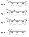
- FIGs 5-8 illustrate a non-limiting, exemplary method by which a fuel cell unit is fabricated according to embodiments of the present invention.
- a substrate 502 is provided.
- a plurality of fuel cell component layers 802 ( Figure 8) is disposed on substrate 502 by at least one physical vapor deposition process, wherein each layer comprises an edge 804 ( Figure 8) bordering the layer.
- a dense layer 806 of material is disposed by the at least one physical vapor deposition process over at least a portion of edge 804 of at least one fuel cell component layer 802 to seal edge 804.
- substrate 502 comprises an interconnect having internal channels 504 patterned into its surface.
- Channels are filled with sacrificial material 506 to create a planar surface prior to disposing the component layers 802 (Figure 8).
- a cathode layer 508 is disposed on substrate 502 by at least one PVD process. Shadow mask 510 is applied to selectively deposit cathode layer 508 in a desired area.
- a dense electrolyte layer 602 is disposed over cathode layer 508 by a PVD process. In this step, mask 510 is positioned to allow a larger deposition area, thereby allowing the dense electrolyte 602 material to cover and seal the edges 604 of cathode layer 508.
- an anode layer 702 is disposed by a PVD process, and in this step, mask 510 is positioned to restrict the area of deposition such that the edge 704 of anode 702 does not overlap edge 706 of electrolyte 602.
- the dense layer 806 is disposed by a PVD process, and mask 510 is positioned to selectively apply dense layer 806 over edge 704 of anode 702.
- the method further comprises disposing at least one diffusion barrier layer (not shown) on at least one component of the fuel cell selected from the group consisting of a. substrate 502 and b. at least one individual layer of the plurality of fuel cell component layers 802. Diffusion barrier layers are used to avoid intermixing, via solid state diffusion, of different layer materials.
- the at least one diffusion barrier layer is disposed using a physical vapor deposition process. Those skilled in the art will appreciate that the selection of a suitable diffusion barrier layer material depends upon, for instance, the materials desired to be contained by the barrier layer, the temperature and expected lifetime of the fuel cell, cost, and the like.
- disposing at least one diffusion barrier layer comprises disposing a material comprising an oxide, such as, for example, an oxide selected from the group consisting of cerium-gadolinium oxide and samarium-doped cerium oxide.
- Cerium-gadolinium oxide is used in the art to reduce the interdiffusion and chemical interaction between a layer of YSZ and a layer of lanthanum cobaltite, lanthanum strontium ferrite or mixtures thereof, while samarium-doped cerium oxide (Ce 1-x Sm x O 2-0.5x ) is used in the art to reduce the interdiffusion and chemical interaction between materials such as nickel oxide, cerium oxide, and other oxide materials used in anodes of solid oxide fuel cells.
- an oxide such as, for example, an oxide selected from the group consisting of cerium-gadolinium oxide and samarium-doped cerium oxide.
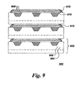
- Fuel cell unit 902 further comprises a least one dense layer 912 of material disposed over at least a portion of edge 910 of at least one fuel cell component layer 908.
- the at least one dense layer 912 seals, and, in some embodiments, substantially hermetically seals, at least the portion of the edge 910 on which it is disposed.
- fuel cell assembly 900 in certain embodiments, further comprises at least one diffusion barrier, as described previously, disposed on at least one component of the fuel cell assembly 900 selected from the group consisting of substrate 902 and at least one individual layer of said plurality of fuel cell component layers 908.
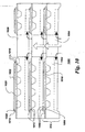
- FIG. 10 depicts a further embodiment of the present invention.
- fuel cell assembly 1000 comprises a substrate 1002, and substrate 1002 comprises an interconnect.
- Substrate 1002 further comprises at least one through-thickness hole 1004.
- Edge 1006 of each fuel cell component layer 1008 comprises a proximal portion 1010 adjacent to hole 1004 and a distal portion 1012 opposite to proximal portion 1010.
- the at least one dense layer 1014 is disposed over at least the distal portion 1012 of edge 1006.
- Such an arrangement allows for the fabrication of an internally manifolded fuel cell assembly, where the at least one dense layer 1014 serves to seal the cell edges.
- the application of dense layers 1014 is especially facilitated by the use of PVD processes according to embodiments of the present invention, because these methods are used to apply thin, dense, substantially hermetic layers without the need for mechanical manipulation of the unit.
- the at least one fuel cell unit 1016 comprises an interconnect substrate 1002 and a cathode layer 1018 disposed on the substrate.
- a dense electrolyte layer 1020 is disposed over cathode 1018. Electrolyte layer 1020 overlaps substantially all of the edge 1006 of cathode layer 1018. Because it is a dense layer, electrolyte 1020 substantially hermetically seals cathode layer 1018 from the remainder of the plurality of layers 1008.
- An anode layer 1022 is disposed over electrolyte layer 1020, and a dense layer 1014 of material is disposed over distal portion 1024 of edge of cathode layer 1022.
- An internally manifolded fuel cell assembly 1000 thus comprises a plurality of fuel cell units 1016.
- the units 1016 are electrically connected to each other and stacked such that through thickness holes 1004 are aligned to allow flow of gas within the assembly 1000.
- the resulting gas passageway 1026 may be used to supply gas to the assembly 1000 or as an exhaust port to take gas away from the assembly 1000, and in general, both types of passageways (supply and exhaust) will be used in a fuel cell assembly 1000.
Landscapes
- Chemical & Material Sciences (AREA)
- Life Sciences & Earth Sciences (AREA)
- Engineering & Computer Science (AREA)
- Manufacturing & Machinery (AREA)
- Sustainable Development (AREA)
- Sustainable Energy (AREA)
- Chemical Kinetics & Catalysis (AREA)
- Electrochemistry (AREA)
- General Chemical & Material Sciences (AREA)
- Inorganic Chemistry (AREA)
- Fuel Cell (AREA)
Applications Claiming Priority (2)
| Application Number | Priority Date | Filing Date | Title |
|---|---|---|---|
| US10/249,086 US20040180252A1 (en) | 2003-03-14 | 2003-03-14 | Fuel cell and method for manufacturing fuel cell |
| US249086 | 2003-03-14 |
Publications (1)
| Publication Number | Publication Date |
|---|---|
| EP1458043A1 true EP1458043A1 (de) | 2004-09-15 |
Family
ID=32770063
Family Applications (1)
| Application Number | Title | Priority Date | Filing Date |
|---|---|---|---|
| EP04251437A Withdrawn EP1458043A1 (de) | 2003-03-14 | 2004-03-12 | Brennstoffzelle und Methode zu deren Herstellung |
Country Status (4)
| Country | Link |
|---|---|
| US (1) | US20040180252A1 (de) |
| EP (1) | EP1458043A1 (de) |
| JP (1) | JP2004281400A (de) |
| CA (1) | CA2459693A1 (de) |
Cited By (2)
| Publication number | Priority date | Publication date | Assignee | Title |
|---|---|---|---|---|
| EP1793444A2 (de) | 2005-11-30 | 2007-06-06 | Deutsches Zentrum für Luft- und Raumfahrt e.V. | Hochtemperatur-Brennstoffzelle und Verfahren zur Herstellung einer Hochtemperatur-Brennstoffzelle |
| EP2538474A3 (de) * | 2011-06-21 | 2014-12-17 | Samsung Electro-Mechanics Co., Ltd | Material für Festoxidbrennstoffzelle, Kathode mit dem Material und Festoxidbrennstoffzelle mit dem Material |
Families Citing this family (19)
| Publication number | Priority date | Publication date | Assignee | Title |
|---|---|---|---|---|
| JP2004507876A (ja) * | 2000-09-01 | 2004-03-11 | グローバル サーモエレクトリック インコーポレイテッド | 固体イオンデバイス用電極パターン |
| US7348087B2 (en) * | 2003-07-28 | 2008-03-25 | Hewlett-Packard Development Company, L.P. | Fuel cell with integral manifold |
| JP4715135B2 (ja) * | 2004-09-08 | 2011-07-06 | トヨタ自動車株式会社 | 燃料電池の製造方法および燃料電池 |
| US20060228613A1 (en) * | 2005-04-07 | 2006-10-12 | Bourgeois Richard S | System and method for manufacturing fuel cell stacks |
| EP2031681A1 (de) * | 2007-08-31 | 2009-03-04 | The Technical University of Denmark | Horizontal abgestufte Strukturen für elektrochemische und elektronische Vorrichtungen |
| WO2011005965A2 (en) * | 2009-07-08 | 2011-01-13 | Rensselaer Polytechnic Institute | Pore formation by in situ etching of nanorod electrodes |
| DE202010017875U1 (de) * | 2009-09-25 | 2012-11-28 | Oerlikon Trading Ag, Trübbach | Anode für Funkenverdampfung |
| US20130108943A1 (en) * | 2010-05-04 | 2013-05-02 | Jean Yamanis | Two-layer coatings on metal substrates and dense electrolyte for high specific power metal-supported sofc |
| US20130122393A1 (en) * | 2011-06-15 | 2013-05-16 | Lg Fuel Cell Systems, Inc. | Fuel cell system with interconnect |
| JP6219856B2 (ja) * | 2012-02-24 | 2017-10-25 | アラン・デヴォー | 燃料電池デバイスを作製する方法 |
| CA2895125A1 (en) * | 2012-12-19 | 2014-06-26 | Zhien LIU | Fuel cell system with interconnect |
| JP6511431B2 (ja) | 2013-03-15 | 2019-05-15 | エルジー フューエル セル システムズ インクLg Fuel Cell Systems Inc. | クロムを捕捉するよう構成された燃料電池システム |
| WO2016014578A1 (en) | 2014-07-21 | 2016-01-28 | Lg Fuel Cell Systems, Inc. | Composition for fuel cell electrode |
| US10115974B2 (en) | 2015-10-28 | 2018-10-30 | Lg Fuel Cell Systems Inc. | Composition of a nickelate composite cathode for a fuel cell |
| DE102015224835A1 (de) * | 2015-12-10 | 2017-06-14 | Volkswagen Aktiengesellschaft | Verfahren zum Herstellen einer Brennstoffzelle, eine mit dem Verfahren herstellbare Brennstoffzelle sowie Brennstoffzellenstapel |
| WO2018226966A1 (en) * | 2017-06-08 | 2018-12-13 | Board Of Trustees Of Michigan State University | Magnetic-field-assisted plasma coating system |
| CN110190210B (zh) * | 2019-03-12 | 2024-05-24 | 华电电力科学研究院有限公司 | 一种便于边缘封接的固体氧化物燃料电池结构 |
| US12224165B2 (en) | 2019-12-06 | 2025-02-11 | Board Of Trustees Of Michigan State University | Magnetic-field-assisted plasma coating system |
| US20230016315A1 (en) * | 2021-07-14 | 2023-01-19 | Battelle Energy Alliance, Llc | Electrochemical cells comprising a ternary oxide material and related systems and methods |
Citations (4)
| Publication number | Priority date | Publication date | Assignee | Title |
|---|---|---|---|---|
| US4345985A (en) * | 1979-12-26 | 1982-08-24 | Nissan Motor Company, Limited | Method of producing solid electrolyte oxygen-sensing element of laminated structure |
| DE19515457C1 (de) * | 1995-04-27 | 1996-07-25 | Mtu Friedrichshafen Gmbh | Brennstoffzelle |
| US5827415A (en) * | 1994-09-26 | 1998-10-27 | The Board Of Trustees Of Leland Stanford Jun. Univ. | Oxygen sensor |
| DE19829142A1 (de) * | 1998-06-30 | 2000-01-05 | Manhattan Scientifics Inc | Gasdichter Verbund aus Bipolarplatte und Membran-Elektroden-Einheit von Polymerelektrolytmembran-Brennstoffzellen |
Family Cites Families (16)
| Publication number | Priority date | Publication date | Assignee | Title |
|---|---|---|---|---|
| US5169731A (en) * | 1990-04-24 | 1992-12-08 | Yoshida Kogyo K.K. | Solid oxide fuel cell and method for manufacturing the same |
| US5348776A (en) * | 1991-04-23 | 1994-09-20 | Osaka Gas Company Limited | Method of producing interconnectors for solid oxide electrolyte fuel cells |
| JPH05275096A (ja) * | 1992-03-27 | 1993-10-22 | Yoshida Kogyo Kk <Ykk> | 固体電解質燃料電池用緻密質基板、それを用いた固体電解質燃料電池及びその製造方法 |
| US5403461A (en) * | 1993-03-10 | 1995-04-04 | Massachusetts Institute Of Technology | Solid electrolyte-electrode system for an electrochemical cell |
| GB9403234D0 (en) * | 1994-02-19 | 1994-04-13 | Rolls Royce Plc | A solid oxide fuel cell stack and a reactant distribution member therefor |
| JPH07245115A (ja) * | 1994-03-03 | 1995-09-19 | Murata Mfg Co Ltd | 固体電解質型燃料電池 |
| US5753385A (en) * | 1995-12-12 | 1998-05-19 | Regents Of The University Of California | Hybrid deposition of thin film solid oxide fuel cells and electrolyzers |
| US5989634A (en) * | 1997-06-25 | 1999-11-23 | Isenberg; Arnold O. | Process of manufacturing solid oxygen ion conducting oxide layers |
| JP3553378B2 (ja) * | 1998-02-19 | 2004-08-11 | 三菱重工業株式会社 | 円筒固体電解質型燃料電池 |
| US6428920B1 (en) * | 2000-05-18 | 2002-08-06 | Corning Incorporated | Roughened electrolyte interface layer for solid oxide fuel cells |
| US6558831B1 (en) * | 2000-08-18 | 2003-05-06 | Hybrid Power Generation Systems, Llc | Integrated SOFC |
| US6632554B2 (en) * | 2001-04-10 | 2003-10-14 | Hybrid Power Generation Systems, Llc | High performance cathodes for solid oxide fuel cells |
| JP3858261B2 (ja) * | 2001-05-22 | 2006-12-13 | 日産自動車株式会社 | 燃料電池用セル板、その製造方法および固体電解質型燃料電池 |
| JP4845296B2 (ja) * | 2001-07-30 | 2011-12-28 | 京セラ株式会社 | 固体電解質型燃料電池セル及び燃料電池 |
| US6495279B1 (en) * | 2001-10-02 | 2002-12-17 | Ford Global Technologies, Inc. | Ultrahigh power density miniaturized solid-oxide fuel cell |
| US6787264B2 (en) * | 2002-05-28 | 2004-09-07 | General Electric Company | Method for manufacturing fuel cells, and articles made therewith |
-
2003
- 2003-03-14 US US10/249,086 patent/US20040180252A1/en not_active Abandoned
-
2004
- 2004-03-04 CA CA002459693A patent/CA2459693A1/en not_active Abandoned
- 2004-03-12 EP EP04251437A patent/EP1458043A1/de not_active Withdrawn
- 2004-03-12 JP JP2004069874A patent/JP2004281400A/ja not_active Withdrawn
Patent Citations (4)
| Publication number | Priority date | Publication date | Assignee | Title |
|---|---|---|---|---|
| US4345985A (en) * | 1979-12-26 | 1982-08-24 | Nissan Motor Company, Limited | Method of producing solid electrolyte oxygen-sensing element of laminated structure |
| US5827415A (en) * | 1994-09-26 | 1998-10-27 | The Board Of Trustees Of Leland Stanford Jun. Univ. | Oxygen sensor |
| DE19515457C1 (de) * | 1995-04-27 | 1996-07-25 | Mtu Friedrichshafen Gmbh | Brennstoffzelle |
| DE19829142A1 (de) * | 1998-06-30 | 2000-01-05 | Manhattan Scientifics Inc | Gasdichter Verbund aus Bipolarplatte und Membran-Elektroden-Einheit von Polymerelektrolytmembran-Brennstoffzellen |
Non-Patent Citations (1)
| Title |
|---|
| PATENT ABSTRACTS OF JAPAN vol. 0171, no. 65 (E - 1343) 30 March 1993 (1993-03-30) * |
Cited By (3)
| Publication number | Priority date | Publication date | Assignee | Title |
|---|---|---|---|---|
| EP1793444A2 (de) | 2005-11-30 | 2007-06-06 | Deutsches Zentrum für Luft- und Raumfahrt e.V. | Hochtemperatur-Brennstoffzelle und Verfahren zur Herstellung einer Hochtemperatur-Brennstoffzelle |
| EP1793444A3 (de) * | 2005-11-30 | 2008-06-18 | Deutsches Zentrum für Luft- und Raumfahrt e.V. | Hochtemperatur-Brennstoffzelle und Verfahren zur Herstellung einer Hochtemperatur-Brennstoffzelle |
| EP2538474A3 (de) * | 2011-06-21 | 2014-12-17 | Samsung Electro-Mechanics Co., Ltd | Material für Festoxidbrennstoffzelle, Kathode mit dem Material und Festoxidbrennstoffzelle mit dem Material |
Also Published As
| Publication number | Publication date |
|---|---|
| US20040180252A1 (en) | 2004-09-16 |
| CA2459693A1 (en) | 2004-09-14 |
| JP2004281400A (ja) | 2004-10-07 |
Similar Documents
| Publication | Publication Date | Title |
|---|---|---|
| EP1458043A1 (de) | Brennstoffzelle und Methode zu deren Herstellung | |
| EP1334528B1 (de) | Brennstoffzellen | |
| US6972161B2 (en) | Fuel cell assembly and method of making the same | |
| KR102737957B1 (ko) | 금속 지지형 전기 화학 소자, 고체 산화물형 연료 전지 및 금속 지지형 전기 화학 소자의 제조 방법 | |
| US10784521B2 (en) | Multi-layered coating providing corrosion resistance to zirconia based electrolytes | |
| US6772501B2 (en) | Apparatus and method for the design and manufacture of thin-film electrochemical devices | |
| WO2010030300A1 (en) | Metal-supported, segmented-in-series high temperature electrochemical device | |
| US8252366B2 (en) | Method for making toughened electrode-supported ceramic fuel cells | |
| US20070072046A1 (en) | Electrochemcial cell structures and methods of making the same | |
| US9343769B2 (en) | Fuel cell and a method of manufacturing a fuel cell | |
| CA2989585A1 (en) | Fuel cell system including dense oxygen barrier layer | |
| US20240379983A1 (en) | Electrochemical cells with support ribs and manufacturing methods thereof | |
| US8709673B2 (en) | Fuel cell and a method of manufacturing a fuel cell | |
| HK1054123B (en) | Fuel cells | |
| JPH05258759A (ja) | 固体電解質型燃料電池 |
Legal Events
| Date | Code | Title | Description |
|---|---|---|---|
| PUAI | Public reference made under article 153(3) epc to a published international application that has entered the european phase |
Free format text: ORIGINAL CODE: 0009012 |
|
| AK | Designated contracting states |
Kind code of ref document: A1 Designated state(s): AT BE BG CH CY CZ DE DK EE ES FI FR GB GR HU IE IT LI LU MC NL PL PT RO SE SI SK TR |
|
| AX | Request for extension of the european patent |
Extension state: AL HR LT LV MK |
|
| 17P | Request for examination filed |
Effective date: 20050315 |
|
| AKX | Designation fees paid |
Designated state(s): CH DE GB LI |
|
| STAA | Information on the status of an ep patent application or granted ep patent |
Free format text: STATUS: THE APPLICATION IS DEEMED TO BE WITHDRAWN |
|
| 18D | Application deemed to be withdrawn |
Effective date: 20111001 |