EP1457981A2 - Dispositif à disque magnétique - Google Patents
Dispositif à disque magnétique Download PDFInfo
- Publication number
- EP1457981A2 EP1457981A2 EP03025047A EP03025047A EP1457981A2 EP 1457981 A2 EP1457981 A2 EP 1457981A2 EP 03025047 A EP03025047 A EP 03025047A EP 03025047 A EP03025047 A EP 03025047A EP 1457981 A2 EP1457981 A2 EP 1457981A2
- Authority
- EP
- European Patent Office
- Prior art keywords
- data
- tracks
- magnetic disk
- read
- written
- Prior art date
- Legal status (The legal status is an assumption and is not a legal conclusion. Google has not performed a legal analysis and makes no representation as to the accuracy of the status listed.)
- Granted
Links
Images


Classifications
-
- G—PHYSICS
- G11—INFORMATION STORAGE
- G11B—INFORMATION STORAGE BASED ON RELATIVE MOVEMENT BETWEEN RECORD CARRIER AND TRANSDUCER
- G11B5/00—Recording by magnetisation or demagnetisation of a record carrier; Reproducing by magnetic means; Record carriers therefor
- G11B5/02—Recording, reproducing, or erasing methods; Read, write or erase circuits therefor
-
- G—PHYSICS
- G11—INFORMATION STORAGE
- G11B—INFORMATION STORAGE BASED ON RELATIVE MOVEMENT BETWEEN RECORD CARRIER AND TRANSDUCER
- G11B19/00—Driving, starting, stopping record carriers not specifically of filamentary or web form, or of supports therefor; Control thereof; Control of operating function ; Driving both disc and head
- G11B19/02—Control of operating function, e.g. switching from recording to reproducing
- G11B19/04—Arrangements for preventing, inhibiting, or warning against double recording on the same blank or against other recording or reproducing malfunctions
-
- G—PHYSICS
- G11—INFORMATION STORAGE
- G11B—INFORMATION STORAGE BASED ON RELATIVE MOVEMENT BETWEEN RECORD CARRIER AND TRANSDUCER
- G11B5/00—Recording by magnetisation or demagnetisation of a record carrier; Reproducing by magnetic means; Record carriers therefor
- G11B5/02—Recording, reproducing, or erasing methods; Read, write or erase circuits therefor
- G11B5/09—Digital recording
Definitions
- the present invention relates to a technique for preventing a data loss as a result of deletion of data on adjacent tracks that may occur when data on a given track is written repeatedly in a magnetic disk device.
- Fig. 2 shows a mechanism of a typical magnetic disk device.
- the disk device comprises: magnetic disks 201 each of which consists of a disk of a non-magnetic material such as glass on which a magnetic layer is laminated; write heads for writing data to the magnetic disks; and read heads for reading data from the magnetic disks.
- pairs of one write head and one read head constitute an integrated magnetic head construction 202.
- the magnetic disks 201 are held on a single spindle 203.
- the heads 202 whose number corresponds to the number of surfaces of the magnetic disks are attached to arms 204.
- the arms 204 are configured so that they can be moved onto the disk surfaces by a VCM (voice coil motor) 205.
- VCM voice coil motor
- Fig. 3 shows the placement of the tracks 302 on the magnetic disk 301.
- the tracks 302 are disposed so that they are typically spaced uniformly from each other by a track pitch 303 and each track 302 consists of servo areas where information that is needed for positioning the heads and data areas to/from which a user can write/read data. Further, each data area can be divided into minimum accessible units called sectors.
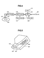
- Fig. 4 shows basic components required for writing/reading data on/from the magnetic disk device.
- the data is sent from a host computer 401 to a hard disk controller (HDC) 402.
- the HDC 402 determines an address or the head, track and sector number to which the data is written and issues a command to a servo controller 404 to move a write head 407 to a specified sector position.
- the servo controller 404 moves the write head to the track in which the desired sector resides.
- the HDC 402 outputs the write data to the R/W channel 405 in synchronization with the sector specified on the track of the rotating magnetic disk 409.
- the write data is encoded into a format suitable for writing in the R/W channel 405 and the R/W amplifier 406 and, then, the encoded write date is written on the magnetic disk 409 by a write head 407.
- the data from the host computer is typically stored in a data buffer 403 once and, then, sent from the data buffer 403 to the R/W channel when the writing is ready.
- the head is positioned on the track where the desired sector resides in a manner similar to the one when the data is written.
- the data is read from the magnetic disk 409 by a read head 408 in synchronization with the specified sector, the read waveform is decoded into the original data by the R/W amplifier 406 and the R/W channel 405 and, then, the decoded data is sent to the HDC 402. Finally, the HDC 402 outputs the data to the host computer.
- the data is written or read in the procedure described above.
- the addresses specified by the host computer when it accesses the magnetic disk device are called logical addresses, which are not always the same as physical addresses or actual addresses on the disk.
- a MPU 410 calculates the corresponding physical addresses from the logical addresses specified by the host computer 401 and the actual write/read operation is performed on the addresses.
- the data is written or read in the order of logical addresses.
- a recording density such as by increasing a track recording density of the disk, which is a density in the circumferential direction, or by reducing the track width as well as the track pitch to increase the track density.
- Fig. 5 shows a structural schematic view of the write head.
- a coil 503 When a coil 503 is energized, a magnetic field is generated between a floating upper surface portion 504 of a head of an upper pole piece 502 and a lower pole piece 501 and, then, as this magnetic field magnetizes the magnetic disk surface, the data is written.
- the tip portion of the write head becomes narrower, the tip portion may be saturated by the magnetic field.
- the magnetic field may not only be generated at the floating upper surface portion 504 as it should be, but also be leaked from side surfaces 505. Further, when the track pitch is narrow, this leakage magnetic field from the side surfaces may be spread to adjacent tracks.
- the leakage magnetic field is weaker than the main write magnetic field to write the data, even if the leakage magnetic field is spread to the adjacent tracks, the data on the adjacent tracks may not be affected immediately. However, as the adjacent tracks are exposed to the leakage magnetic field multiple times, the data on the adjacent tracks may be deleted little by little and, eventually, the data may become unreadable.
- examples of the measures include: (1) to increase a coercive force of the magnetic disk so that the data may be not liable to be deleted even if there is the leakage magnetic field from the adjacent tracks; and (2) to configure the write head such that the leakage magnetic field may not be liable to be generated.
- other examples of the measures include: (3) to reduce the amount of the leakage magnetic field to which the adjacent tracks are exposed by increasing the track pitch; and (4) to reduce the amount of the leakage magnetic field itself by adjusting the magnitude of the current applied to the write head when the data is written or an amount of overshoot of the write current waveform.
- the track recording density in order to ensure the storage capacity per disk, the track recording density must be increased in proportion to the track pitch, but the higher track recording density may allow resolution and S/N ratio of the readout waveform to be reduced and, therefore, the error rate may be degraded. Still further, with regard to the setting of the write current value and the adjustment of the overshoot of the write current as discussed in item (4), if such measures are taken so that the leakage magnetic field will not occur or, more specifically, if the write current value is set to a smaller value or the amount of overshoot is reduced, the data itself may be written insufficiently and, consequently, the error rate may be degraded just as in the case described with regard to item (1).
- a magnetic disk device comprising: a magnetic disk for recording data; a magnetic head for writing or reading the data on or from the magnetic disk; and a write and read circuit, connected to the magnetic head, for writing or reading the data; wherein the data is written or read to or from a plurality of tracks in the form of concentric circles disposed on the magnetic disk; and wherein the number of write of data on a given track is acquired and it is detected that the number of write reaches a predetermined number, and based on the detection, data on tracks adjacent to the given track is read out once and, then, the read-out data is rewritten to the adjacent tracks.
- a magnetic disk device comprising: a magnetic disk for recording data; a magnetic head for writing or reading the data on or from the magnetic disk; and a write and read circuit, connected to the magnetic head, for writing or reading the data; wherein the data is written or read to or from a plurality of tracks in the form of concentric circles disposed on the magnetic disk; and wherein all tracks on the magnetic disk are divided into a plurality of areas, the number of write of data on even-numbered physical tracks in the divided areas is acquired and it is detected that the number of write reaches a predetermined number, and based on the detection, data on odd-numbered physical tracks in the divided areas is read out once and, then, the read-out data is rewritten on the odd-numbered tracks.
- a magnetic disk device comprising: a magnetic disk for recording data; a magnetic head for writing or reading the data on or from the magnetic disk; and a write and read circuit, connected to the magnetic head, for writing or reading the data; wherein the data is written or read to or from a plurality of tracks in the form of concentric circles disposed on the magnetic disk; and wherein all tracks on the magnetic disk are divided into a plurality of areas, the number of write of data on odd-numbered physical tracks in the divided areas is acquired and it is detected that the number of write reaches a predetermined number, and based on the detection, data on even-numbered physical tracks in the divided areas is read out once and, then, the read-out data is rewritten on the even-numbered tracks.
- the magnetic disk device may be configured such that, when the data is written on the tracks, the data is written on alternate physical tracks and every other track is skipped and, after the data is written on half of all the tracks, the data is written on the skipped tracks.
- the number of data write on a magnetic disk surface reaches the predetermined number, on the assumption that it may be possible that data on a track adjacent to the track in question is about to be deleted, the data is refreshed or, more specifically, the data written on the magnetic disk surface is read out once and, then, rewritten on the same track.
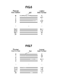
- Fig. 6 is a diagram showing an example of a correspondence between physical track numbers and logical track numbers on a magnetic disk.
- Fig. 7 is a diagram showing another example of a correspondence between physical track numbers and logical track numbers on a magnetic disk.
- the physical track numbers are associated with the logical track numbers as shown in Fig. 6, wherein the logical track numbers indicate order when the magnetic disk device is actually used.
- the data is written on the magnetic disk surface in the order of 0, 2, 4, ... of the physical track numbers.
- the data is not written on adjacent tracks and, therefore, even when the data is written repeatedly, there is no possibility that the adjacent tracks are deleted by the leakage magnetic field and it is not necessary to refresh the data.
- the method shown in Fig. 7 can also be adopted as an embodiment of the present invention.
- the number of write on each magnetic disk may be recorded for both even- and odd-numbered physical tracks separately. In this case, for example, when the number of write on the even-numbered physical tracks reaches the predetermined number, it is needed only to refresh the data on the odd-numbered physical tracks and, conversely, when the number of write on the odd-numbered physical tracks reaches a predetermined number, it is needed only to refresh the data on the even-numbered physical tracks and, consequently, the time required to refresh the data can be reduced.
- each disk surface is divided into several areas as shown in Fig. 8 and the number of write of the data for each area is recorded and, then, it is determined whether or not a refreshing operation is needed for each area.
- the number of write for each track is monitored so as to refresh the data on the tracks adjacent to the monitored tracks and, further, the data is recorded on alternate physical tracks and, after half of all the tracks have been occupied, the data is written on the tracks that have been skipped.
- the magnetic disk surfaces are divided into areas and the number of write and the refresh of the data is managed for each area. In this case, it is needed only to refresh the data on the restricted number of tracks and, therefore, it can be avoided that the areas that are still not needed to be refreshed may be refreshed uselessly and, consequently, the time required for refreshment can be reduced.
- Fig. 9 is a diagram showing a state in which the number of write on both even- or odd-numbered physical tracks is recorded on a memory for each area on a given magnetic disk surface according to this embodiment.
- the tracks are designated by the physical track numbers, even unless explicitly stated.
- even [1] refers to a variation indicating the number of write on even-numbered physical tracks residing in the area number 1 and this value is recorded on the memory as, for example, even [1] 900.
- the number of write is not always equal among all even-numbered tracks in the area number 1, it may be reasonable to record the maximum value of the number of write on any one track in the area number 1.
- the magnetic disk device having a plurality of magnetic disk surfaces is provided with the tables as shown in Fig. 9 as many as the magnetic disk surfaces.
- the number of write on the even-numbered tracks in the area y is stored in even [y] and the number of write on the odd-numbered tracks in the area y is stored in odd [y]. When the magnetic disk device is shipped, all these values are 0.
- the magnetic disk device when the magnetic disk device is activated, the values of the number of write up to the previous time that have been recorded in the non-volatile memory are read and, then, the values are put on the RAM and, then, while the magnetic disk device is in operation, the values on the RAM are read or updated. Then, before the magnetic disk device is de-energized, the values on the RAM are rewritten in the non-volatile memory. Since there is a possibility that the magnetic disk device is de-energized suddenly, it is preferable to save the values on the RAM to the non-volatile memory not only at the moment when the magnetic disk device is turned off but also from time to time.
- Fig. 1 shows a procedure for determining whether a data refresh process is needed or not when data is written on a track x and a procedure after the refresh process is performed.
- the track x belongs to an area y in the following description.
- step 101 it is determined whether even-numbered or odd-numbered the track x is. The following description will be given on the assumption that the track x is even-numbered.
- step 104 If odd [y] is not 0, or if the data has already been written on the odd-numbered tracks, the process proceeds to step 104 and the value of even [y] is incremented by 1 (the number of write on the even-numbered tracks in the area y is incremented by 1).
- the number of write on the even-numbered tracks is determined in step 105 in this embodiment. More specifically, in this case, it is determined whether the number of write on the even-numbered tracks reaches a threshold value p at which the refresh is needed. If the value of even [y] is less than the threshold value p, it is determined that the refresh is not needed and the process in ended (106). However, if the value of even [y] is not less than the threshold value p, it is determined that there is a possibility that the refresh is needed and the process continues.
- the refresh process may be performed at once but, alternatively, another procedure shown in step 107 (see steps in a dotted box in Fig. 1) may be taken wherein the data on the odd-numbered tracks in the area y, which has been written temporarily to refresh the data, is read out once (108) and, then, if the number of retry attempts exceeds a predetermined value, it is determined that the data is about to be deleted actually (109) and the data is rewritten.
- the retry attempts are performed to read the data in the same portion repeatedly up to a few tens or a hundred times until the data is read properly and, then, if the data has not been failed completely, the data may often be read by the retry attempts.
- Fig. 1 when the data on the odd-numbered tracks in the area y in question is read, if the number of retry attempts reaches a predetermined value q, it is determined that the data in the area becomes less readable in actuality in step 109. Then, if it is determined that the data must be rewritten, the data is rewritten in step 110 (the data on all the odd-numbered tracks in the area y is rewritten). If the number of retry attempts is small and it is determined that the refresh is not needed yet, the data is not rewritten.
- the data that has been read once is stored on a high-speed memory such as RAM temporarily until it is determined whether the data must be rewritten so that it would not be necessary to read the data in the area in question that has been read once again (so that it would not be necessary to repeat step 108) when it would be determined that the data must be rewritten actually (for example, when the threshold value p is reached in step 105).
- a high-speed memory such as RAM temporarily until it is determined whether the data must be rewritten so that it would not be necessary to read the data in the area in question that has been read once again (so that it would not be necessary to repeat step 108) when it would be determined that the data must be rewritten actually (for example, when the threshold value p is reached in step 105).
- step 107 When the process shown in step 107 is not performed, it will be more cost effective if the refresh is performed, not by the procedure in which all the data in the area to be refreshed is read out once and then rewritten, but by the procedure in which the data is read and then written at once by small blocks (for example, by 100 tracks/block instead of 4000 - 5000 tracks/area) repeatedly, because it is not necessary to prepare the large-capacity memory to store the read data until it is rewritten in the latter case.
- small blocks for example, by 100 tracks/block instead of 4000 - 5000 tracks/area
- the number of write on the even-numbered tracks can be reset to 1 (111).
- the checking procedure by reading the data before rewriting as shown in step 107 may be performed. More specifically, the procedure in which the refresh process is not performed soon after the number of write reaches the threshold value p but it is determined whether the refresh is needed or not after the data is read out once may be adopted.
- step 112 by subtracting r from the value of even [y] in advance, the condition even [y] ⁇ p is not satisfied in step 105 until the data is written on the even-numbered tracks in the area y over r times. Therefore, the read checking procedure to determine whether the refresh is needed or not is not performed meanwhile. This inhibits that the read checking procedure (108) to determine whether the refresh is needed or not is performed too frequently.
- p, q and r may vary depending on the combination of the magnetic disks and heads used actually or the write current value, it is preferable that the values of p, q and r may be variable parameters defined separately for each disk surface or each area.
- Fig. 1 if the track x is an odd-numbered track, the process goes from step 101 to step 113 but, after that, the process is similar to the one described with reference to the left side of Fig. 1, although the even-numbered tracks are substituted by the odd-numbered tracks.
- the present invention principally provides the configuration and functions or operations as follows: That is, the number of write is counted and, if the number of write exceeds a predetermined number, the refresh operation to read once and then write the data is performed.
- logical track numbers are assigned to alternate physical tracks and the number of write is counted separately for even-numbered and odd-numbered physical tracks.
- the data subject to the refresh operation can be restricted and the time required for the refresh operation can be saved.
- the phenomenon in which the data is deleted by the leakage magnetic field from the side surfaces of the write head can be prevented until half of the entire capacity of the magnetic disk is used.
- the data can be recovered for a shorter time and more effectively.
Applications Claiming Priority (2)
| Application Number | Priority Date | Filing Date | Title |
|---|---|---|---|
| JP2003064974 | 2003-03-11 | ||
| JP2003064974A JP4063694B2 (ja) | 2003-03-11 | 2003-03-11 | 磁気ディスク装置 |
Publications (3)
| Publication Number | Publication Date |
|---|---|
| EP1457981A2 true EP1457981A2 (fr) | 2004-09-15 |
| EP1457981A3 EP1457981A3 (fr) | 2005-10-05 |
| EP1457981B1 EP1457981B1 (fr) | 2007-01-03 |
Family
ID=32767907
Family Applications (1)
| Application Number | Title | Priority Date | Filing Date |
|---|---|---|---|
| EP03025047A Expired - Fee Related EP1457981B1 (fr) | 2003-03-11 | 2003-10-30 | Dispositif à disque magnétique |
Country Status (8)
| Country | Link |
|---|---|
| US (1) | US7177979B2 (fr) |
| EP (1) | EP1457981B1 (fr) |
| JP (1) | JP4063694B2 (fr) |
| KR (1) | KR100584065B1 (fr) |
| CN (1) | CN1275226C (fr) |
| DE (1) | DE60310873T2 (fr) |
| SG (1) | SG118215A1 (fr) |
| TW (1) | TWI254917B (fr) |
Cited By (5)
| Publication number | Priority date | Publication date | Assignee | Title |
|---|---|---|---|---|
| EP1564736A2 (fr) * | 2004-02-16 | 2005-08-17 | Samsung Electronics Co., Ltd. | Méthode d' enregistrement de données avec protection contre l'effacement de pistes adjacents et support d'enrigistrement avec cette méthode. |
| EP1569220A2 (fr) * | 2004-01-30 | 2005-08-31 | Samsung Electronics Co., Ltd. | méthode automatique de re-enregistrement des données pour système d'emmagasinage de données et tourne-disque utilisant ceci |
| EP1715478A2 (fr) | 2005-04-12 | 2006-10-25 | Samsung Electronics Co., Ltd. | Méthode de protection des données sur le support d'enregistrement et programme de stockage du support d'enregistrement pour exécuter la méthode |
| EP1975935A3 (fr) * | 2007-03-26 | 2008-10-29 | Hitachi Global Storage Technologies Netherlands B.V. | Dispositif de lecteur de disque et son procédé de réécriture de données |
| GB2525081A (en) * | 2014-03-04 | 2015-10-14 | Inodyn Newmedia Gmbh | Method for efficient write operations on a data carrier with overlapping data tracks and device thereof |
Families Citing this family (54)
| Publication number | Priority date | Publication date | Assignee | Title |
|---|---|---|---|---|
| JP3778171B2 (ja) * | 2003-02-20 | 2006-05-24 | 日本電気株式会社 | ディスクアレイ装置 |
| US7606969B2 (en) * | 2003-12-05 | 2009-10-20 | Davinder Aggarwal | Programmable logic devices |
| US7174414B2 (en) * | 2003-12-23 | 2007-02-06 | Samsung Electronics Co., Ltd. | Method and apparatus mapping logical tracks in a disk drive for optimizing track seek time |
| US7475276B2 (en) * | 2004-05-07 | 2009-01-06 | Equallogic, Inc. | Method for maintaining track data integrity in magnetic disk storage devices |
| US20060066971A1 (en) * | 2004-09-30 | 2006-03-30 | Hitachi Global Storage Technologies Netherlands B.V. | System and method for ameliorating the effects of adjacent track erasure in magnetic data storage device |
| US7227708B2 (en) * | 2004-11-10 | 2007-06-05 | Hitachi Global Storage Technologies Netherlands B.V. | System and method for determining long-range erasure of adjacent tracks in hard disk drive |
| TWI257044B (en) * | 2004-11-26 | 2006-06-21 | Hon Hai Prec Ind Co Ltd | Apparatus and method for prolonging useful life of non-volatile memory |
| US7345837B1 (en) * | 2004-12-02 | 2008-03-18 | Maxtor Corporation | Disk drive that refreshes data on portions of a disk based on a number of write operations thereto |
| JP2006179102A (ja) | 2004-12-22 | 2006-07-06 | Hitachi Global Storage Technologies Netherlands Bv | 磁気ディスク装置及データの記録方法 |
| US7772477B2 (en) * | 2005-03-17 | 2010-08-10 | Yamaha Corporation | Electronic music apparatus with data loading assist |
| US7567400B2 (en) * | 2005-04-27 | 2009-07-28 | Hitachi Global Storage Technologies Netherlands B.V. | Method and apparatus for improving the error rate of track information on a magnetic storage device |
| US7721029B2 (en) * | 2005-11-02 | 2010-05-18 | Spectra Logic Corporation | Data restoration in archivable mobile random access storage devices |
| JP2007164887A (ja) * | 2005-12-13 | 2007-06-28 | Fujitsu Ltd | 磁気ディスク装置の試験方法 |
| JP2007242207A (ja) | 2006-03-13 | 2007-09-20 | Fujitsu Ltd | ディスク装置の媒体スキャン方法 |
| JP2007250054A (ja) * | 2006-03-15 | 2007-09-27 | Fujitsu Ltd | 情報記録方法、書込制御回路及び情報記憶装置 |
| JP2008010113A (ja) * | 2006-06-30 | 2008-01-17 | Fujitsu Ltd | 磁気ディスク制御装置、磁気ディスク装置および読取り障害修復方法 |
| US7729077B2 (en) * | 2006-08-30 | 2010-06-01 | Stmicroelectronics, Inc. | Disk drive write driver and associated control logic circuitry |
| US7774539B2 (en) | 2007-02-07 | 2010-08-10 | Lenovo (Singapore) Pte. Ltd | Preservation of hard drive data via dynamic band boundary definition |
| JP2008217077A (ja) * | 2007-02-28 | 2008-09-18 | Nec Corp | ディスクアレイ装置、ディスクアレイコントローラ及びプログラム |
| JP2008217076A (ja) * | 2007-02-28 | 2008-09-18 | Nec Corp | ディスクアレイ装置、ディスクアレイコントローラ及びプログラム |
| US7817370B2 (en) * | 2007-03-28 | 2010-10-19 | Lenovo (Singapore) Pte. Ltd. | System and method to avoid disk lube pooling |
| JP5002306B2 (ja) * | 2007-04-03 | 2012-08-15 | 株式会社日立製作所 | ハードディスク装置 |
| US7872822B1 (en) | 2007-06-26 | 2011-01-18 | Western Digital Technologies, Inc. | Disk drive refreshing zones based on serpentine access of disk surfaces |
| US8174780B1 (en) | 2007-06-27 | 2012-05-08 | Western Digital Technologies, Inc. | Disk drive biasing a refresh monitor with write parameter of a write operation |
| US7945727B2 (en) * | 2007-07-27 | 2011-05-17 | Western Digital Technologies, Inc. | Disk drive refreshing zones in segments to sustain target throughput of host commands |
| KR20100051665A (ko) * | 2007-08-22 | 2010-05-17 | 톰슨 라이센싱 | 투명한 웨어 레벨링을 위한 하드디스크 섹터/트랙 리매핑 |
| JPWO2009040929A1 (ja) * | 2007-09-28 | 2011-01-13 | 東芝ストレージデバイス株式会社 | 記憶装置、制御方法及び制御装置 |
| JP4282733B1 (ja) * | 2007-12-13 | 2009-06-24 | 株式会社東芝 | ディスク記憶装置及びデータ書き込み方法 |
| JP4991599B2 (ja) * | 2008-02-28 | 2012-08-01 | 株式会社東芝 | 磁気ディスク装置及びデータ記憶方法 |
| US7864476B2 (en) * | 2008-03-20 | 2011-01-04 | Kabushiki Kaisha Toshiba | Low track-per-inch (TPI) zone with reduced need for adjacent-track-erasure (ATE) refresh |
| US20090244775A1 (en) * | 2008-03-31 | 2009-10-01 | Kabushiki Kaisha Toshiba 1-1 | Adjacent-track-erasure (ate) refresh with increased track resolution for often-written areas |
| US8190810B2 (en) * | 2008-04-18 | 2012-05-29 | Silicon Motion, Inc. | Non-volatile memory apparatus and method for accessing a non-volatile memory apparatus |
| JP4469906B2 (ja) | 2008-07-17 | 2010-06-02 | 株式会社東芝 | 磁気ディスク装置及び同装置におけるデータリフレッシュ方法 |
| JP4504450B1 (ja) * | 2008-12-26 | 2010-07-14 | 株式会社東芝 | 磁気ディスク装置及び同装置におけるデータリフレッシュ方法 |
| JP2010157278A (ja) * | 2008-12-26 | 2010-07-15 | Toshiba Corp | ディスク記憶装置及び欠陥処理方法 |
| JP5264630B2 (ja) * | 2009-06-23 | 2013-08-14 | エイチジーエスティーネザーランドビーブイ | 磁気ディスク・ドライブ及びそのデータの書き直し方法 |
| JP4660613B2 (ja) * | 2009-07-24 | 2011-03-30 | 株式会社東芝 | 磁気ディスクドライブにおけるデータリフレッシュ方法 |
| US7974029B2 (en) * | 2009-07-31 | 2011-07-05 | Western Digital Technologies, Inc. | Disk drive biasing refresh zone counters based on write commands |
| CN102023938B (zh) * | 2009-09-18 | 2013-04-24 | 鸿富锦精密工业(深圳)有限公司 | 电子装置及断电保护方法 |
| US8331053B2 (en) * | 2009-09-25 | 2012-12-11 | Lenovo (Singapore) Pte. Ltd. | Systems and methods for adjacent track interference (ATI) risk management |
| JP4869416B2 (ja) * | 2010-02-25 | 2012-02-08 | 株式会社東芝 | 磁気ディスク装置及び同装置におけるデータリフレッシュ方法 |
| US8320067B1 (en) * | 2010-05-18 | 2012-11-27 | Western Digital Technologies, Inc. | Refresh operations using write/read commands |
| JP4865062B2 (ja) * | 2010-06-30 | 2012-02-01 | 株式会社東芝 | 磁気ディスク装置及び同装置におけるリフレッシュ方法 |
| US8531793B2 (en) * | 2010-07-19 | 2013-09-10 | HGST Netherlands B.V. | Disk drive with variable incremented counting of writes to the data tracks for minimizing the effect of far track erasure |
| US8599510B1 (en) | 2011-05-04 | 2013-12-03 | Western Digital Technologies, Inc. | Disk drive adjusting data track density based on write condition when writing to contiguous data tracks |
| US8590050B2 (en) | 2011-05-11 | 2013-11-19 | International Business Machines Corporation | Security compliant data storage management |
| US8531791B1 (en) | 2012-02-01 | 2013-09-10 | Western Digital Technologies, Inc. | Methods for adaptive throttling of data refresh operations and disk drives implementing the same |
| JP6155768B2 (ja) * | 2013-03-29 | 2017-07-05 | 富士通株式会社 | ストレージ制御装置、ストレージ制御プログラム及びストレージ制御方法 |
| CN104900240B (zh) | 2014-03-04 | 2018-03-23 | 株式会社东芝 | 硬盘装置及数据刷新方法 |
| US9082458B1 (en) | 2014-03-10 | 2015-07-14 | Western Digital Technologies, Inc. | Data storage device balancing and maximizing quality metric when configuring arial density of each disk surface |
| US9129658B1 (en) | 2014-05-07 | 2015-09-08 | Kabushiki Kaisha Toshiba | Magnetic disk drive and method for controlling data rewrite |
| US9530442B1 (en) | 2015-09-23 | 2016-12-27 | Western Digital Technologies, Inc. | Enhanced low overhead data protection in data storage drives |
| US10228870B2 (en) | 2016-02-04 | 2019-03-12 | Seagate Technology Llc | Redundant write transfer detection |
| JP2020047345A (ja) * | 2018-09-19 | 2020-03-26 | 株式会社東芝 | 磁気ディスク装置および記録電流適正化方法 |
Citations (6)
| Publication number | Priority date | Publication date | Assignee | Title |
|---|---|---|---|---|
| US4516165A (en) * | 1982-12-27 | 1985-05-07 | International Business Machines Corporation | Error recovery procedure using selective erasure |
| EP0581362A1 (fr) * | 1992-07-30 | 1994-02-02 | International Business Machines Corporation | Système et méthode pour la prévention de pertes de données d'un système de stockage de données à accès direct, dû à un choc mécanique pendant une opération d'écriture |
| JP2001338468A (ja) * | 2000-05-26 | 2001-12-07 | Hitachi Ltd | 記憶装置の制御方法および記憶装置 |
| JP2001350596A (ja) * | 2000-06-06 | 2001-12-21 | Sony Corp | 記憶装置 |
| US20020030915A1 (en) * | 1998-01-12 | 2002-03-14 | Hitachi, Ltd. | Method of controlling read write operation of a magnetic disk apparatus |
| WO2002027723A1 (fr) * | 2000-09-27 | 2002-04-04 | Seagate Technology Llc | Procede permettant d'obtenir une densite superieure de piste avec une tolerance d'un seul empietement sur piste une face |
Family Cites Families (6)
| Publication number | Priority date | Publication date | Assignee | Title |
|---|---|---|---|---|
| JPH05250105A (ja) * | 1992-03-06 | 1993-09-28 | Nec Field Service Ltd | 情報処理装置 |
| JPH05334015A (ja) * | 1992-06-03 | 1993-12-17 | Hokkaido Nippon Denki Software Kk | 磁気ディスク装置障害通報方式 |
| JPH06236504A (ja) | 1993-02-08 | 1994-08-23 | Hitachi Ltd | 磁気記録再生装置 |
| JP2001014606A (ja) * | 1999-06-25 | 2001-01-19 | Hitachi Ltd | 磁気ディスク装置 |
| US6462896B1 (en) * | 2000-11-30 | 2002-10-08 | Western Digital Technologies, Inc. | Method for minimizing adjacent track data loss during a write operation in a disk drive |
| US6785752B2 (en) * | 2001-03-23 | 2004-08-31 | International Business Machines Corporation | Method for dynamically adjusting buffer utilization ratios in a hard disk drive system |
-
2003
- 2003-03-11 JP JP2003064974A patent/JP4063694B2/ja not_active Expired - Fee Related
- 2003-09-29 US US10/674,763 patent/US7177979B2/en active Active
- 2003-10-30 DE DE60310873T patent/DE60310873T2/de not_active Expired - Lifetime
- 2003-10-30 EP EP03025047A patent/EP1457981B1/fr not_active Expired - Fee Related
- 2003-11-12 TW TW092131695A patent/TWI254917B/zh not_active IP Right Cessation
- 2003-11-28 CN CNB2003101157416A patent/CN1275226C/zh not_active Expired - Fee Related
- 2003-11-28 SG SG200307007A patent/SG118215A1/en unknown
- 2003-11-29 KR KR1020030085900A patent/KR100584065B1/ko not_active IP Right Cessation
Patent Citations (6)
| Publication number | Priority date | Publication date | Assignee | Title |
|---|---|---|---|---|
| US4516165A (en) * | 1982-12-27 | 1985-05-07 | International Business Machines Corporation | Error recovery procedure using selective erasure |
| EP0581362A1 (fr) * | 1992-07-30 | 1994-02-02 | International Business Machines Corporation | Système et méthode pour la prévention de pertes de données d'un système de stockage de données à accès direct, dû à un choc mécanique pendant une opération d'écriture |
| US20020030915A1 (en) * | 1998-01-12 | 2002-03-14 | Hitachi, Ltd. | Method of controlling read write operation of a magnetic disk apparatus |
| JP2001338468A (ja) * | 2000-05-26 | 2001-12-07 | Hitachi Ltd | 記憶装置の制御方法および記憶装置 |
| JP2001350596A (ja) * | 2000-06-06 | 2001-12-21 | Sony Corp | 記憶装置 |
| WO2002027723A1 (fr) * | 2000-09-27 | 2002-04-04 | Seagate Technology Llc | Procede permettant d'obtenir une densite superieure de piste avec une tolerance d'un seul empietement sur piste une face |
Non-Patent Citations (2)
| Title |
|---|
| PATENT ABSTRACTS OF JAPAN vol. 2002, no. 04, 4 August 2002 (2002-08-04) & JP 2001 338468 A (HITACHI LTD), 7 December 2001 (2001-12-07) * |
| PATENT ABSTRACTS OF JAPAN vol. 2002, no. 04, 4 August 2002 (2002-08-04) & JP 2001 350596 A (SONY CORP), 21 December 2001 (2001-12-21) * |
Cited By (10)
| Publication number | Priority date | Publication date | Assignee | Title |
|---|---|---|---|---|
| EP1569220A2 (fr) * | 2004-01-30 | 2005-08-31 | Samsung Electronics Co., Ltd. | méthode automatique de re-enregistrement des données pour système d'emmagasinage de données et tourne-disque utilisant ceci |
| EP1569220A3 (fr) * | 2004-01-30 | 2006-12-20 | Samsung Electronics Co., Ltd. | méthode automatique de re-enregistrement des données pour système d'emmagasinage de données et tourne-disque utilisant ceci |
| US7463441B2 (en) | 2004-01-30 | 2008-12-09 | Samsung Electronics Co., Ltd. | Automatic data update method of data storage system and disk drive using the same |
| EP1564736A2 (fr) * | 2004-02-16 | 2005-08-17 | Samsung Electronics Co., Ltd. | Méthode d' enregistrement de données avec protection contre l'effacement de pistes adjacents et support d'enrigistrement avec cette méthode. |
| EP1564736A3 (fr) * | 2004-02-16 | 2006-12-20 | Samsung Electronics Co., Ltd. | Méthode d' enregistrement de données avec protection contre l'effacement de pistes adjacents et support d'enrigistrement avec cette méthode. |
| EP1715478A2 (fr) | 2005-04-12 | 2006-10-25 | Samsung Electronics Co., Ltd. | Méthode de protection des données sur le support d'enregistrement et programme de stockage du support d'enregistrement pour exécuter la méthode |
| EP1715478A3 (fr) * | 2005-04-12 | 2007-11-07 | Samsung Electronics Co., Ltd. | Méthode de protection des données sur le support d'enregistrement et programme de stockage du support d'enregistrement pour exécuter la méthode |
| EP1975935A3 (fr) * | 2007-03-26 | 2008-10-29 | Hitachi Global Storage Technologies Netherlands B.V. | Dispositif de lecteur de disque et son procédé de réécriture de données |
| GB2525081A (en) * | 2014-03-04 | 2015-10-14 | Inodyn Newmedia Gmbh | Method for efficient write operations on a data carrier with overlapping data tracks and device thereof |
| GB2525081B (en) * | 2014-03-04 | 2017-03-22 | Inodyn Newmedia Gmbh | Method for efficient write operations on a data carrier with overlapping data tracks and device thereof |
Also Published As
| Publication number | Publication date |
|---|---|
| JP4063694B2 (ja) | 2008-03-19 |
| JP2004273060A (ja) | 2004-09-30 |
| US20040193798A1 (en) | 2004-09-30 |
| SG118215A1 (en) | 2006-01-27 |
| EP1457981A3 (fr) | 2005-10-05 |
| EP1457981B1 (fr) | 2007-01-03 |
| US7177979B2 (en) | 2007-02-13 |
| KR20040080909A (ko) | 2004-09-20 |
| DE60310873D1 (de) | 2007-02-15 |
| CN1530930A (zh) | 2004-09-22 |
| DE60310873T2 (de) | 2007-09-06 |
| TWI254917B (en) | 2006-05-11 |
| KR100584065B1 (ko) | 2006-05-29 |
| TW200417993A (en) | 2004-09-16 |
| CN1275226C (zh) | 2006-09-13 |
Similar Documents
| Publication | Publication Date | Title |
|---|---|---|
| EP1457981B1 (fr) | Dispositif à disque magnétique | |
| US6462896B1 (en) | Method for minimizing adjacent track data loss during a write operation in a disk drive | |
| US6809893B2 (en) | Information refresh method, storage system and storage medium thereof | |
| EP0447246B1 (fr) | Méthode de récupération de données pour un dispositif de stockage de données à disque magnétique | |
| EP1715478B1 (fr) | Méthode de protection des données sur le support d'enregistrement et programme de stockage du support d'enregistrement pour exécuter la méthode | |
| US6084729A (en) | Storage device for reliably maintaining data in a reproducible state for a long period of time | |
| CA1147054A (fr) | Appareil d'enregistrement a memoire tampon | |
| US8724248B2 (en) | Method and apparatus for compensating vibration by adjusting track pitch | |
| US6516426B1 (en) | Disc storage system having non-volatile write cache | |
| US7119974B2 (en) | Storing data to magnetic tape both to one set of tracks and in the same operation rewritten to another set of tracks | |
| EP0639825B1 (fr) | Procédure de récupération de données utilisateur | |
| US20080174905A1 (en) | Method and apparatus for recording data on a magnetic recording medium | |
| KR100468767B1 (ko) | 하드디스크드라이브에서 인접트랙에 대한 오버라이트를방지하기 위한 방법 및 그 장치 | |
| US7483230B2 (en) | Write-current control chip and magnetic disk drive using the same | |
| KR100532411B1 (ko) | 온도에 따른 데이터 저장 시스템 제어 방법 및 장치 | |
| US7487388B2 (en) | Method of recovering reallocation sectors in data storage system and disc drive using the same | |
| EP1396846B1 (fr) | Procédé et dispositif de commande pour unité de disque dur | |
| US10424334B1 (en) | Data storage device formatting a disk surface with a write format and a read format | |
| JPH0652508A (ja) | テープ駆動装置におけるテープ上のエラーを検出して補正する方法と装置 | |
| JP4544412B2 (ja) | データ保存システムにおけるリトライ改善方法,ディスクドライブ及びコンピュータ読み取り可能な記憶媒体 | |
| US10607643B2 (en) | Magnetic disk device and recording method | |
| JP3792404B2 (ja) | 磁気記憶装置 | |
| US20050154950A1 (en) | Method for saving self-test output to both flash and media | |
| CN115116479A (zh) | 磁盘装置 | |
| US20050154951A1 (en) | Saving self-test output to both flash and media |
Legal Events
| Date | Code | Title | Description |
|---|---|---|---|
| PUAI | Public reference made under article 153(3) epc to a published international application that has entered the european phase |
Free format text: ORIGINAL CODE: 0009012 |
|
| AK | Designated contracting states |
Kind code of ref document: A2 Designated state(s): AT BE BG CH CY CZ DE DK EE ES FI FR GB GR HU IE IT LI LU MC NL PT RO SE SI SK TR |
|
| AX | Request for extension of the european patent |
Extension state: AL LT LV MK |
|
| PUAL | Search report despatched |
Free format text: ORIGINAL CODE: 0009013 |
|
| AK | Designated contracting states |
Kind code of ref document: A3 Designated state(s): AT BE BG CH CY CZ DE DK EE ES FI FR GB GR HU IE IT LI LU MC NL PT RO SE SI SK TR |
|
| AX | Request for extension of the european patent |
Extension state: AL LT LV MK |
|
| RIC1 | Information provided on ipc code assigned before grant |
Ipc: 7G 11B 19/04 A Ipc: 7G 11B 15/04 B Ipc: 7G 11B 5/596 B Ipc: 7G 11B 5/012 B |
|
| 17P | Request for examination filed |
Effective date: 20060331 |
|
| AKX | Designation fees paid |
Designated state(s): DE FR GB |
|
| GRAP | Despatch of communication of intention to grant a patent |
Free format text: ORIGINAL CODE: EPIDOSNIGR1 |
|
| GRAS | Grant fee paid |
Free format text: ORIGINAL CODE: EPIDOSNIGR3 |
|
| GRAA | (expected) grant |
Free format text: ORIGINAL CODE: 0009210 |
|
| AK | Designated contracting states |
Kind code of ref document: B1 Designated state(s): DE FR GB |
|
| REG | Reference to a national code |
Ref country code: GB Ref legal event code: FG4D |
|
| REF | Corresponds to: |
Ref document number: 60310873 Country of ref document: DE Date of ref document: 20070215 Kind code of ref document: P |
|
| ET | Fr: translation filed | ||
| PLBE | No opposition filed within time limit |
Free format text: ORIGINAL CODE: 0009261 |
|
| STAA | Information on the status of an ep patent application or granted ep patent |
Free format text: STATUS: NO OPPOSITION FILED WITHIN TIME LIMIT |
|
| 26N | No opposition filed |
Effective date: 20071005 |
|
| PGFP | Annual fee paid to national office [announced via postgrant information from national office to epo] |
Ref country code: GB Payment date: 20141029 Year of fee payment: 12 Ref country code: DE Payment date: 20141023 Year of fee payment: 12 Ref country code: FR Payment date: 20141008 Year of fee payment: 12 |
|
| REG | Reference to a national code |
Ref country code: DE Ref legal event code: R119 Ref document number: 60310873 Country of ref document: DE |
|
| GBPC | Gb: european patent ceased through non-payment of renewal fee |
Effective date: 20151030 |
|
| PG25 | Lapsed in a contracting state [announced via postgrant information from national office to epo] |
Ref country code: GB Free format text: LAPSE BECAUSE OF NON-PAYMENT OF DUE FEES Effective date: 20151030 Ref country code: DE Free format text: LAPSE BECAUSE OF NON-PAYMENT OF DUE FEES Effective date: 20160503 |
|
| REG | Reference to a national code |
Ref country code: FR Ref legal event code: ST Effective date: 20160630 |
|
| PG25 | Lapsed in a contracting state [announced via postgrant information from national office to epo] |
Ref country code: FR Free format text: LAPSE BECAUSE OF NON-PAYMENT OF DUE FEES Effective date: 20151102 |