EP1457712A1 - Mécanisme de blocage pour le différentiel d'un arbre d'essieux - Google Patents
Mécanisme de blocage pour le différentiel d'un arbre d'essieux Download PDFInfo
- Publication number
- EP1457712A1 EP1457712A1 EP04075336A EP04075336A EP1457712A1 EP 1457712 A1 EP1457712 A1 EP 1457712A1 EP 04075336 A EP04075336 A EP 04075336A EP 04075336 A EP04075336 A EP 04075336A EP 1457712 A1 EP1457712 A1 EP 1457712A1
- Authority
- EP
- European Patent Office
- Prior art keywords
- set forth
- drive axle
- assembly
- axle assembly
- differential case
- Prior art date
- Legal status (The legal status is an assumption and is not a legal conclusion. Google has not performed a legal analysis and makes no representation as to the accuracy of the status listed.)
- Withdrawn
Links
- 239000012530 fluid Substances 0.000 claims description 17
- 241000239290 Araneae Species 0.000 claims description 6
- 230000003321 amplification Effects 0.000 claims description 2
- 238000003199 nucleic acid amplification method Methods 0.000 claims description 2
- 230000005540 biological transmission Effects 0.000 description 2
- 238000007789 sealing Methods 0.000 description 2
- 239000000969 carrier Substances 0.000 description 1
- 230000007812 deficiency Effects 0.000 description 1
- 239000000463 material Substances 0.000 description 1
- 238000012986 modification Methods 0.000 description 1
- 230000004048 modification Effects 0.000 description 1
- 238000004806 packaging method and process Methods 0.000 description 1
- 238000003825 pressing Methods 0.000 description 1
Images


Classifications
-
- F—MECHANICAL ENGINEERING; LIGHTING; HEATING; WEAPONS; BLASTING
- F16—ENGINEERING ELEMENTS AND UNITS; GENERAL MEASURES FOR PRODUCING AND MAINTAINING EFFECTIVE FUNCTIONING OF MACHINES OR INSTALLATIONS; THERMAL INSULATION IN GENERAL
- F16H—GEARING
- F16H48/00—Differential gearings
- F16H48/20—Arrangements for suppressing or influencing the differential action, e.g. locking devices
- F16H48/22—Arrangements for suppressing or influencing the differential action, e.g. locking devices using friction clutches or brakes
-
- B—PERFORMING OPERATIONS; TRANSPORTING
- B60—VEHICLES IN GENERAL
- B60K—ARRANGEMENT OR MOUNTING OF PROPULSION UNITS OR OF TRANSMISSIONS IN VEHICLES; ARRANGEMENT OR MOUNTING OF PLURAL DIVERSE PRIME-MOVERS IN VEHICLES; AUXILIARY DRIVES FOR VEHICLES; INSTRUMENTATION OR DASHBOARDS FOR VEHICLES; ARRANGEMENTS IN CONNECTION WITH COOLING, AIR INTAKE, GAS EXHAUST OR FUEL SUPPLY OF PROPULSION UNITS IN VEHICLES
- B60K17/00—Arrangement or mounting of transmissions in vehicles
- B60K17/04—Arrangement or mounting of transmissions in vehicles characterised by arrangement, location, or kind of gearing
- B60K17/16—Arrangement or mounting of transmissions in vehicles characterised by arrangement, location, or kind of gearing of differential gearing
-
- F—MECHANICAL ENGINEERING; LIGHTING; HEATING; WEAPONS; BLASTING
- F16—ENGINEERING ELEMENTS AND UNITS; GENERAL MEASURES FOR PRODUCING AND MAINTAINING EFFECTIVE FUNCTIONING OF MACHINES OR INSTALLATIONS; THERMAL INSULATION IN GENERAL
- F16D—COUPLINGS FOR TRANSMITTING ROTATION; CLUTCHES; BRAKES
- F16D25/00—Fluid-actuated clutches
- F16D25/08—Fluid-actuated clutches with fluid-actuated member not rotating with a clutching member
- F16D25/082—Fluid-actuated clutches with fluid-actuated member not rotating with a clutching member the line of action of the fluid-actuated members co-inciding with the axis of rotation
- F16D25/087—Fluid-actuated clutches with fluid-actuated member not rotating with a clutching member the line of action of the fluid-actuated members co-inciding with the axis of rotation the clutch being actuated by the fluid-actuated member via a diaphragm spring or an equivalent array of levers
-
- F—MECHANICAL ENGINEERING; LIGHTING; HEATING; WEAPONS; BLASTING
- F16—ENGINEERING ELEMENTS AND UNITS; GENERAL MEASURES FOR PRODUCING AND MAINTAINING EFFECTIVE FUNCTIONING OF MACHINES OR INSTALLATIONS; THERMAL INSULATION IN GENERAL
- F16H—GEARING
- F16H48/00—Differential gearings
- F16H48/06—Differential gearings with gears having orbital motion
- F16H48/08—Differential gearings with gears having orbital motion comprising bevel gears
-
- F—MECHANICAL ENGINEERING; LIGHTING; HEATING; WEAPONS; BLASTING
- F16—ENGINEERING ELEMENTS AND UNITS; GENERAL MEASURES FOR PRODUCING AND MAINTAINING EFFECTIVE FUNCTIONING OF MACHINES OR INSTALLATIONS; THERMAL INSULATION IN GENERAL
- F16H—GEARING
- F16H48/00—Differential gearings
- F16H48/20—Arrangements for suppressing or influencing the differential action, e.g. locking devices
- F16H48/30—Arrangements for suppressing or influencing the differential action, e.g. locking devices using externally-actuatable means
- F16H48/34—Arrangements for suppressing or influencing the differential action, e.g. locking devices using externally-actuatable means using electromagnetic or electric actuators
-
- F—MECHANICAL ENGINEERING; LIGHTING; HEATING; WEAPONS; BLASTING
- F16—ENGINEERING ELEMENTS AND UNITS; GENERAL MEASURES FOR PRODUCING AND MAINTAINING EFFECTIVE FUNCTIONING OF MACHINES OR INSTALLATIONS; THERMAL INSULATION IN GENERAL
- F16H—GEARING
- F16H48/00—Differential gearings
- F16H48/20—Arrangements for suppressing or influencing the differential action, e.g. locking devices
- F16H2048/204—Control of arrangements for suppressing differential actions
-
- F—MECHANICAL ENGINEERING; LIGHTING; HEATING; WEAPONS; BLASTING
- F16—ENGINEERING ELEMENTS AND UNITS; GENERAL MEASURES FOR PRODUCING AND MAINTAINING EFFECTIVE FUNCTIONING OF MACHINES OR INSTALLATIONS; THERMAL INSULATION IN GENERAL
- F16H—GEARING
- F16H2200/00—Transmissions for multiple ratios
- F16H2200/20—Transmissions using gears with orbital motion
- F16H2200/203—Transmissions using gears with orbital motion characterised by the engaging friction means not of the freewheel type, e.g. friction clutches or brakes
- F16H2200/2071—Transmissions using gears with orbital motion characterised by the engaging friction means not of the freewheel type, e.g. friction clutches or brakes using three freewheel mechanism
-
- F—MECHANICAL ENGINEERING; LIGHTING; HEATING; WEAPONS; BLASTING
- F16—ENGINEERING ELEMENTS AND UNITS; GENERAL MEASURES FOR PRODUCING AND MAINTAINING EFFECTIVE FUNCTIONING OF MACHINES OR INSTALLATIONS; THERMAL INSULATION IN GENERAL
- F16H—GEARING
- F16H48/00—Differential gearings
- F16H48/20—Arrangements for suppressing or influencing the differential action, e.g. locking devices
- F16H48/30—Arrangements for suppressing or influencing the differential action, e.g. locking devices using externally-actuatable means
- F16H48/32—Arrangements for suppressing or influencing the differential action, e.g. locking devices using externally-actuatable means using fluid pressure actuators
-
- F—MECHANICAL ENGINEERING; LIGHTING; HEATING; WEAPONS; BLASTING
- F16—ENGINEERING ELEMENTS AND UNITS; GENERAL MEASURES FOR PRODUCING AND MAINTAINING EFFECTIVE FUNCTIONING OF MACHINES OR INSTALLATIONS; THERMAL INSULATION IN GENERAL
- F16H—GEARING
- F16H48/00—Differential gearings
- F16H48/38—Constructional details
- F16H48/40—Constructional details characterised by features of the rotating cases
Definitions
- This invention relates generally to a differential assembly for a drive axle assembly, and more particularly to a locking mechanism for the differential assembly.
- Vehicle drive axles typically include a pair of axle shafts for driving vehicle wheels.
- the drive axle uses a differential assembly to control input speed and torque to the axle shafts.
- the wheels will be turning at approximately the same speed and the torque will be equally split between both wheels.
- the outer wheel must travel over a greater distance than the inner wheel.
- the differential assembly allows the inner wheel to turn at a slower speed than the outer wheel as the vehicle turns.
- Power is transmitted from a vehicle drive shaft to a drive pinion that is in constant mesh with a ring gear.
- the ring gear is bolted to a differential case that turns with the ring gear.
- a differential spider having four (4) support shafts orientated in the shape of a cross, has four (4) differential pinions.
- One differential pinion is supported for rotation on each support shaft.
- Power is transferred from the differential case to side gears that are splined to the axle shafts.
- the side gears are in constant mesh with the differential pinions.
- the outer ends of the axle shafts are bolted to the wheel hubs to which the wheels are mounted.
- the ring gear, differential case, spider, differential pinions, and side gears all rotate as one unit to transfer power to the axle shafts. There is no relative movement between the differential pinions and the side gears.
- the differential pinion gears rotate on their respective shafts to speed up the rotation of one axle shaft while slowing the rotation of the other axle shaft.
- the differential assembly includes a differential locking or biasing mechanism.
- the locking mechanism allows maximum wheel traction for improved control. If the differential assembly does not have the locking mechanism and one tire is on ice, the available traction torque on the opposite wheel is same as on the wheel on ice. Thus, the tire just spins on the ice and the vehicle is prohibited from traveling forward.
- the locking mechanism allows the axle shafts to rotate at the same speed while transferring most of the available torque to the tire not on the ice. If the tractive effort at this tire is sufficient, the vehicle can be moved off of the ice.
- the mechanism is activated, power is transmitted through the differential gearing, and locking mechanism rather than through the differential gearing only.
- One type of the locking mechanism includes a wet disc clutch that locks the differential case to the axle shafts, until a predetermined torque level is exceeded.
- the wet disc clutch includes a plurality of stationary discs interspersed with rotating discs in a fluid chamber.
- a piston applies a force to the wet disc clutch to compress the rotating and stationary discs of the wet disc clutch together to apply torque between the differential case to be locked to the axle shafts.
- the terms stationary and rotating applied to the disc are relative to the differential case.
- a drive axle assembly includes a carrier and a differential case rotatably disposed in the carrier.
- a pair of axle shafts, disposed within the differential case, are rotatable relative to each other and about an axis.
- a drive hub is disposed about the axle shaft.
- a plurality of friction discs are disposed within the differential case and are alternatively connected to the differential case and the drive hub. The friction discs are adjacent one another in an alternating relationship to define a running clearance therebetween.
- a plurality of levers extends radially relative to the axis between a radially inward end to a radially outward end to engage the friction discs.
- An actuator assembly is disposed about one of the axle shafts for engaging the levers and to force the levers into engagement with the friction discs for forcing the friction discs into engagement with one another for transmitting torque between one of the axle shafts and the differential case.
- Each lever is characterized by the radially inward end engaging the actuator assembly and the radially outward end engaging the differential case having a disc engaging portion between the radial inward and outward ends for engaging the friction discs between the radially inward and outward ends of each lever.
- the disc engaging portion amplifies a thrust force applied by the actuator assembly by pivoting about the engagement of the radially outward end with the differential case in response to axial movement of the radially inward end by the actuator assembly.
- the present invention therefore provides a locking mechanism where an amplified thrust force is transferred from a non-rotatable piston to a plurality of friction discs.
- a unique lever mechanism is provided which amplifies the thrust force on the friction discs. This in turn lowers the actuation force on the differential case bearings.
- Figure 1 is a perspective view of a drive axle assembly
- Figure 2 is a perspective view of a differential assembly
- Figure 3 is another perspective view of the differential assembly
- Figure 4 is a fragmented cross-sectional view of the differential assembly
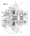
- Figure 5 is another fragmented cross-sectional view of the differential assembly
- Figure 6 is an exploded fragmentary cross-sectional view of the differential assembly of Figure 5 shown in an deactivated mode
- Figure 7 is an exploded fragmentary cross-sectional view of the differential assembly of Figure 5 shown in activated mode
- Figure 8 is a plan view of a plurality of levers interconnected with one another to form a plate.
- Figure 9 is a cross-sectional view taken elongated line 9-9 of Figure 8.
- a drive axle assembly for a vehicle is generally shown at 10 in Figure 1.
- the drive axle assembly 10 transmits torque from an engine (not shown) and a transmission (not shown) to drive a pair of wheels (not shown).
- the drive axle assembly 10 changes direction of a power flow, multiplies torque, and allows different speeds between the wheels.
- the drive axle assembly 10 includes an axle housing 12, and first 14 and second 16 axle shafts, shown in Figures 2 and 3, for driving the wheels, extending through the axle housing 12.
- the drive axle assembly 10 uses a carrier 24, disposed within and supported by the axle housing 12 to transfer input speed and torque to the first 14 and second 16 axle shafts.
- the carrier 24 is a geared mechanism that is mounted to the axle housing 12.
- a differential assembly 18 is mounted to the carrier 24 and is protected by the axle housing 12.
- the differential assembly 18 is operably connected to the first 14 and second 16 axle shafts extending therethrough.
- the carrier 24 has first 36 and second 38 ends and a cavity 40 defined therebetween.
- An annular flange 42 is integral with and extends around the first end 36.
- the annular flange 42 includes a plurality of holes 44 defined therein for facilitating mounting of the carrier 24 to the axle housing 12.
- a pair of stationary towers 48 are spaced diametrically one from another and are connected to and extend from the annular flange 42. Each stationary tower 48, includes a hole 52 defined therein to receive one of the axle shaft 14, 16 extending therethrough.
- Each stationary tower 48 houses side bearings 32, 34, respectively, as best shown in Figures 4 and 5, for facilitating rotational movement of a differential case 22 relative to the carrier 24.
- the differential case 22 includes a fluid chamber 50 defined therein.
- the differential case 22 includes a first half 53 and a second half 54 interconnected to each other with the fluid chamber 50 formed therebetween.
- the differential case 22 rotates with the second axle shaft 16.
- the differential case 22 is partially disposed within the cavity 40 of the carrier 24, as shown in Figure 4, and rotates relative to the carrier 24.
- a ring gear 20 is mounted to the first half 53 of the differential case 22.
- power is transmitted from the engine and the transmission to the drive axle assembly 10 via a longitudinally extending driveshaft (not shown) operably coupled to a pinion gear extending through and supported in the cavity 40 of the carrier 24.
- the pinion gear meshes with the ring gear 20 and to transfers power to the differential case 22.
- the differential assembly 18 includes a differential spider 26, as best shown in Figures 4 and 5, disposed in and is supported by the differential case 22.
- the differential spider 26 has four support shafts 62, 64.
- the support shafts 62, 64 are orientated in the shape of a cross.
- Pinion gears 66 are each supported for rotation on each of the support shafts 62, 64.
- Side gear 28, 30 are splined to each of the respective first 14 and second 16 axle shafts.
- the side gears 28, 30 are in constant mesh with the pinion gears 66.
- This type of differential assembly 18 is well known in the art and will not be discussed in a greater detail.
- the differential case 22 When the vehicle is driven in a straight path the differential case 22, the differential spider 26, and the pinion gears 66 all rotate as one unit to transfer power to the first 14 and second 16 axle shafts. There is no relative movement between the pinion gears 66, and the side gears 28, 30.
- the differential assembly 18 rotates the first 14 and second 16 axle shafts at different speeds when the vehicle turns a comer and allows both axle shafts 14, 16 to turn at the same speed when the vehicle moves in the straight path.
- the differential assembly 18 serves to establish a state of balance between forces between the wheels and allow the wheels to turn at different speeds when the vehicle changes direction.
- the differential assembly 18 includes a locking mechanism comprising a wet disc clutch pack, generally indicated at 72, that locks the differential case 22 to the first axle shaft 14 for transmitting equal torque to the first 14 and second 16 axle shafts and the differential case 22.
- the wet disc clutch pack 72 is mounted within the fluid chamber 50.
- the wet disc clutch pack 72 has a first 74 and second 76 set of friction discs.
- the first 74 and second 76 sets of friction discs are adjacent one another in an alternating relationship and define a running clearance therebetween, wherein, for example, a friction disc from the first set 74 is oriented next to a friction disc from the second set 76.
- the first set of friction discs 74 is mounted to the differential case 22, in particular to the first half 53 of the differential case 22.
- the second set of friction discs 76 is mounted to the first axle shaft 14.
- the second set of the friction discs 76 is operably connected to the first axle shaft 14 via a drive hub 78 disposed annularly about and splined to the first axle shaft 14.
- a pressure plate 80 which is also disposed in the fluid chamber 50 of the differential case 22, abuts the first set of friction discs 74.
- the pressure plate 80 distributes a thrust force uniformly.
- the first set of friction discs 74 compresses with the second set of the friction discs 76 to reduce a rotational speed and to allow the differential case 22 to be locked to the first axle shaft 14.
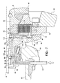
- the locking mechanism includes a stationary section generally indicated at 82 and an actuator assembly, generally indicated at 84.
- the actuator assembly 84 rotates relative to the stationary section 82.
- the stationary section 82 is operably connected and supported by one of the stationary towers 48, extending from and bolted to the annular flange 42 of the carrier 24.
- the stationary section 82 of the locking mechanism includes an adjusting ring 86 operably connected to the stationary tower 48 surrounding the first axle shaft 14 extending therethrough.
- a piston housing 88 is positioned stationary within the adjusting ring 86.
- a piston 90 is positioned stationary within the piston housing 88.
- the piston housing 88 and the piston 90 define a cavity 92 therebetween.
- the cavity 92 is a hydraulic cavity.
- a fluid input or hydraulic inlet 94 is connected to the piston housing 88 for introducing a fluid into the hydraulic cavity 92 for pressurizing the hydraulic cavity 92 thereby pushing the piston 90 away from the piston housing 88.
- the piston 90 applies a force to the wet disc clutch pack 72 to compress the friction discs of the first 74 and second 76 sets together to reduce rotational speed and allow the differential case 22 to be locked to the first axle shaft 14.
- a sealing assembly of the piston 90 includes a top seal 96 and a bottom seal 98.
- the sealing assembly 96, 98 is used to provide a sealed environment as fluid flows from the hydraulic inlet 94 filling the hydraulic cavity 92 between the piston housing 88 and the piston 90.
- the subject invention eliminates fluid leakage by utilizing a new inventive concept of the aforementioned stationary section 82 of the locking mechanism that works in conjunction with the actuator assembly 84.
- the actuator assembly 84 includes a sleeve 100 that moves axially with respect to the axis A and has first 106 and second 108 ends with the first end 106 defining a lip 110.
- a thrust bearing 112 is positioned between the lip 110 and the piston 90 to provide a soft contact between the stationary section 82 and the actuator assembly 84. The thrust bearing 112 rotates about the axis A.
- a plurality of levers 104 extend radially relative to the axis A between a radially inward end 114 to a radially outward end 116 and engage the friction discs of the first 74 and second 76 sets.
- the radially inward end 114 which engages the sleeve 100
- the radially outward end 116 which engages the differential case 22
- This mechanical engagement operates as a second-class lever to amplify the thrust force applied by the sleeve 100.
- the lever 104 pivots about an engagement of the radially outward end 116 with the differential case 22 in response to axial movement of the radially inward end 114 by the actuator assembly.
- the radially outward end 116 operates as a fulcrum of the second-class lever.
- Each of the levers 104 includes an elongated portion 120 extending from the radially inward end 114 to the disc engaging portion 118.
- a length of the elongated portion 120 defines a degree of amplification of the thrust force. It is preferred that the disc engaging portion 118, or fulcrum, remain closer to the radially outward end 116 as opposed to the radially inward end 114.
- the disc engaging portion 118 is generally V-shaped.
- the radially outward end 116 slopes downwardly to the disc engaging portion 118 and then upwardly through a peak 124 to the elongated portion 120.
- the levers 104 may have slightly different configurations, as seen in the differences between the levers 104 shown in Figures 6 and 7 and the levers 104 shown in Figures 8 and 9.
Landscapes
- Engineering & Computer Science (AREA)
- General Engineering & Computer Science (AREA)
- Mechanical Engineering (AREA)
- Chemical & Material Sciences (AREA)
- Combustion & Propulsion (AREA)
- Transportation (AREA)
- Physics & Mathematics (AREA)
- Electromagnetism (AREA)
- Retarders (AREA)
Applications Claiming Priority (2)
| Application Number | Priority Date | Filing Date | Title |
|---|---|---|---|
| US44517103P | 2003-02-04 | 2003-02-04 | |
| US445171P | 2003-02-04 |
Publications (1)
| Publication Number | Publication Date |
|---|---|
| EP1457712A1 true EP1457712A1 (fr) | 2004-09-15 |
Family
ID=32772069
Family Applications (1)
| Application Number | Title | Priority Date | Filing Date |
|---|---|---|---|
| EP04075336A Withdrawn EP1457712A1 (fr) | 2003-02-04 | 2004-02-04 | Mécanisme de blocage pour le différentiel d'un arbre d'essieux |
Country Status (2)
| Country | Link |
|---|---|
| US (1) | US6991572B2 (fr) |
| EP (1) | EP1457712A1 (fr) |
Families Citing this family (7)
| Publication number | Priority date | Publication date | Assignee | Title |
|---|---|---|---|---|
| US8454471B2 (en) | 2010-07-21 | 2013-06-04 | Ford Global Technologies, Llc | Electronic locking differential |
| CN204420041U (zh) * | 2013-08-07 | 2015-06-24 | 伊顿公司 | 差速齿轮组件 |
| JP6187407B2 (ja) * | 2014-07-26 | 2017-08-30 | 株式会社オーエス技研 | 差動制限機構付き差動装置 |
| US11236804B2 (en) | 2020-02-19 | 2022-02-01 | Dana Automotive Systems Group, Llc | Electric drive axle system with removable planetary gear assembly |
| US11518225B2 (en) | 2020-02-19 | 2022-12-06 | Dana Automotive Systems Group, Llc | Electric drive axle with lubrication system |
| US11235660B2 (en) * | 2020-02-19 | 2022-02-01 | Dana Automotive Systems Group, Llc | Electric drive axle system with multi-speed gear train |
| KR20230131944A (ko) * | 2021-04-05 | 2023-09-14 | 히다치 겡키 가부시키 가이샤 | 차량용 액슬 장치 |
Citations (7)
| Publication number | Priority date | Publication date | Assignee | Title |
|---|---|---|---|---|
| US3107766A (en) * | 1961-05-03 | 1963-10-22 | Gen Motors Corp | Friction engaging devices having a lever spring |
| US4644823A (en) * | 1982-04-03 | 1987-02-24 | Dr. Ing. H.C.F. Porsche Aktiengesellschaft | Differential gear |
| US4712659A (en) * | 1986-12-11 | 1987-12-15 | Dana Corporation | Adjustable clutch brake apparatus |
| DE3839787A1 (de) * | 1987-12-03 | 1989-06-15 | Zahnradfabrik Friedrichshafen | Sperrdifferential mit stellkraftverstaerkungshebeln |
| EP0321335A1 (fr) * | 1987-12-17 | 1989-06-21 | Automobiles Peugeot | Système différentiel à glissement variable contrôlé |
| US4848549A (en) * | 1988-04-08 | 1989-07-18 | Chipper Industries, Inc. | Coaxial adjustable hydraulic clutch actuator |
| DE19848582A1 (de) * | 1998-10-21 | 2000-04-27 | Mannesmann Sachs Ag | Selbstverstärkende Reibungskupplung |
-
2004
- 2004-02-04 US US10/771,977 patent/US6991572B2/en not_active Expired - Lifetime
- 2004-02-04 EP EP04075336A patent/EP1457712A1/fr not_active Withdrawn
Patent Citations (7)
| Publication number | Priority date | Publication date | Assignee | Title |
|---|---|---|---|---|
| US3107766A (en) * | 1961-05-03 | 1963-10-22 | Gen Motors Corp | Friction engaging devices having a lever spring |
| US4644823A (en) * | 1982-04-03 | 1987-02-24 | Dr. Ing. H.C.F. Porsche Aktiengesellschaft | Differential gear |
| US4712659A (en) * | 1986-12-11 | 1987-12-15 | Dana Corporation | Adjustable clutch brake apparatus |
| DE3839787A1 (de) * | 1987-12-03 | 1989-06-15 | Zahnradfabrik Friedrichshafen | Sperrdifferential mit stellkraftverstaerkungshebeln |
| EP0321335A1 (fr) * | 1987-12-17 | 1989-06-21 | Automobiles Peugeot | Système différentiel à glissement variable contrôlé |
| US4848549A (en) * | 1988-04-08 | 1989-07-18 | Chipper Industries, Inc. | Coaxial adjustable hydraulic clutch actuator |
| DE19848582A1 (de) * | 1998-10-21 | 2000-04-27 | Mannesmann Sachs Ag | Selbstverstärkende Reibungskupplung |
Also Published As
| Publication number | Publication date |
|---|---|
| US20040185983A1 (en) | 2004-09-23 |
| US6991572B2 (en) | 2006-01-31 |
Similar Documents
| Publication | Publication Date | Title |
|---|---|---|
| US3974717A (en) | Four pinion differential | |
| KR100498819B1 (ko) | 차량용 유성 트랜스미션 | |
| US6398686B1 (en) | Electronically controlled limited slip differential assembly | |
| US5350340A (en) | Lockable differential gear | |
| US7390278B2 (en) | Torque-coupling device for front-wheel-drive transaxle unit | |
| JP2000351336A (ja) | 車輌用の車台 | |
| US6508734B2 (en) | Differential lock actuator | |
| JP2000283183A (ja) | 反作用力回路を持つクラッチ組立体 | |
| JP2003207025A (ja) | 2段階の傾斜角を備えた係合機構 | |
| WO1982002077A1 (fr) | Dispositif d'actionnement de frein a disque de stationnement | |
| KR100562767B1 (ko) | 자성 유체 클러치를 포함한 트랜스퍼 케이스 조립체 및 차동장치 조립체 | |
| EP2006120A2 (fr) | Roue double pour véhicule | |
| KR20000005657A (ko) | 속도비례클러치를구비하는변속기케이스 | |
| US20040254044A1 (en) | Driveline for mobile vehicles | |
| US9005070B2 (en) | Clutch arrangement for a vehicle drive train | |
| US5906249A (en) | Drive system of a drive wheel | |
| US6991572B2 (en) | Differential locking mechanism for a drive axle assembly | |
| JP2007505276A (ja) | 伝動装置アッセンブリ | |
| US6354979B1 (en) | Limited-slip differential | |
| US20030224896A1 (en) | Hydraulic differential lock | |
| US4452100A (en) | Differential speed limiting device | |
| US6536560B1 (en) | Single braking assembly for a drive axle | |
| CN106945459B (zh) | 用于双轮的轮毂结构 | |
| US6554732B1 (en) | Differential assembly with modified limited slip clutch arrangement | |
| EP1132270B1 (fr) | Moyeu de roue pour véhicule automobile |
Legal Events
| Date | Code | Title | Description |
|---|---|---|---|
| PUAI | Public reference made under article 153(3) epc to a published international application that has entered the european phase |
Free format text: ORIGINAL CODE: 0009012 |
|
| AK | Designated contracting states |
Kind code of ref document: A1 Designated state(s): AT BE BG CH CY CZ DE DK EE ES FI FR GB GR HU IE IT LI LU MC NL PT RO SE SI SK TR |
|
| AX | Request for extension of the european patent |
Extension state: AL LT LV MK |
|
| 17P | Request for examination filed |
Effective date: 20050315 |
|
| AKX | Designation fees paid |
Designated state(s): AT BE BG CH CY CZ DE DK EE ES FI FR GB GR HU IE IT LI LU MC NL PT RO SE SI SK TR |
|
| 17Q | First examination report despatched |
Effective date: 20070115 |
|
| STAA | Information on the status of an ep patent application or granted ep patent |
Free format text: STATUS: THE APPLICATION IS DEEMED TO BE WITHDRAWN |
|
| 18D | Application deemed to be withdrawn |
Effective date: 20070526 |