EP1457680A1 - Schleifgerät angetrieben mittels eines Druckluftflügelmotors - Google Patents
Schleifgerät angetrieben mittels eines Druckluftflügelmotors Download PDFInfo
- Publication number
- EP1457680A1 EP1457680A1 EP04005496A EP04005496A EP1457680A1 EP 1457680 A1 EP1457680 A1 EP 1457680A1 EP 04005496 A EP04005496 A EP 04005496A EP 04005496 A EP04005496 A EP 04005496A EP 1457680 A1 EP1457680 A1 EP 1457680A1
- Authority
- EP
- European Patent Office
- Prior art keywords
- sleeve
- rotor
- grinding device
- air
- slides
- Prior art date
- Legal status (The legal status is an assumption and is not a legal conclusion. Google has not performed a legal analysis and makes no representation as to the accuracy of the status listed.)
- Withdrawn
Links
- 238000000227 grinding Methods 0.000 title claims description 14
- 239000000463 material Substances 0.000 claims abstract description 8
- 229920000742 Cotton Polymers 0.000 claims abstract description 4
- 239000004744 fabric Substances 0.000 claims abstract description 4
- 239000005011 phenolic resin Substances 0.000 claims abstract description 4
- CWQXQMHSOZUFJS-UHFFFAOYSA-N molybdenum disulfide Chemical compound S=[Mo]=S CWQXQMHSOZUFJS-UHFFFAOYSA-N 0.000 claims abstract description 3
- KXGFMDJXCMQABM-UHFFFAOYSA-N 2-methoxy-6-methylphenol Chemical compound [CH]OC1=CC=CC([CH])=C1O KXGFMDJXCMQABM-UHFFFAOYSA-N 0.000 claims description 3
- 229920001568 phenolic resin Polymers 0.000 claims description 3
- 239000000470 constituent Substances 0.000 abstract 1
- 229910052982 molybdenum disulfide Inorganic materials 0.000 abstract 1
- 241000209035 Ilex Species 0.000 description 1
- 238000005299 abrasion Methods 0.000 description 1
- 239000000654 additive Substances 0.000 description 1
- 230000000996 additive effect Effects 0.000 description 1
- 238000013016 damping Methods 0.000 description 1
- 230000003247 decreasing effect Effects 0.000 description 1
- 238000011161 development Methods 0.000 description 1
- 230000018109 developmental process Effects 0.000 description 1
- 229920001971 elastomer Polymers 0.000 description 1
- 239000011810 insulating material Substances 0.000 description 1
- 238000004519 manufacturing process Methods 0.000 description 1
- 238000003801 milling Methods 0.000 description 1
- 238000005496 tempering Methods 0.000 description 1
Images

Classifications
-
- B—PERFORMING OPERATIONS; TRANSPORTING
- B24—GRINDING; POLISHING
- B24B—MACHINES, DEVICES, OR PROCESSES FOR GRINDING OR POLISHING; DRESSING OR CONDITIONING OF ABRADING SURFACES; FEEDING OF GRINDING, POLISHING, OR LAPPING AGENTS
- B24B23/00—Portable grinding machines, e.g. hand-guided; Accessories therefor
- B24B23/02—Portable grinding machines, e.g. hand-guided; Accessories therefor with rotating grinding tools; Accessories therefor
- B24B23/026—Fluid driven
-
- F—MECHANICAL ENGINEERING; LIGHTING; HEATING; WEAPONS; BLASTING
- F01—MACHINES OR ENGINES IN GENERAL; ENGINE PLANTS IN GENERAL; STEAM ENGINES
- F01C—ROTARY-PISTON OR OSCILLATING-PISTON MACHINES OR ENGINES
- F01C13/00—Adaptations of machines or engines for special use; Combinations of engines with devices driven thereby
- F01C13/02—Adaptations of machines or engines for special use; Combinations of engines with devices driven thereby for driving hand-held tools or the like
-
- F—MECHANICAL ENGINEERING; LIGHTING; HEATING; WEAPONS; BLASTING
- F01—MACHINES OR ENGINES IN GENERAL; ENGINE PLANTS IN GENERAL; STEAM ENGINES
- F01C—ROTARY-PISTON OR OSCILLATING-PISTON MACHINES OR ENGINES
- F01C21/00—Component parts, details or accessories not provided for in groups F01C1/00 - F01C20/00
- F01C21/08—Rotary pistons
- F01C21/0809—Construction of vanes or vane holders
-
- F—MECHANICAL ENGINEERING; LIGHTING; HEATING; WEAPONS; BLASTING
- F01—MACHINES OR ENGINES IN GENERAL; ENGINE PLANTS IN GENERAL; STEAM ENGINES
- F01C—ROTARY-PISTON OR OSCILLATING-PISTON MACHINES OR ENGINES
- F01C21/00—Component parts, details or accessories not provided for in groups F01C1/00 - F01C20/00
- F01C21/10—Outer members for co-operation with rotary pistons; Casings
- F01C21/104—Stators; Members defining the outer boundaries of the working chamber
- F01C21/106—Stators; Members defining the outer boundaries of the working chamber with a radial surface, e.g. cam rings
-
- F—MECHANICAL ENGINEERING; LIGHTING; HEATING; WEAPONS; BLASTING
- F04—POSITIVE - DISPLACEMENT MACHINES FOR LIQUIDS; PUMPS FOR LIQUIDS OR ELASTIC FLUIDS
- F04C—ROTARY-PISTON, OR OSCILLATING-PISTON, POSITIVE-DISPLACEMENT MACHINES FOR LIQUIDS; ROTARY-PISTON, OR OSCILLATING-PISTON, POSITIVE-DISPLACEMENT PUMPS
- F04C18/00—Rotary-piston pumps specially adapted for elastic fluids
- F04C18/30—Rotary-piston pumps specially adapted for elastic fluids having the characteristics covered by two or more of groups F04C18/02, F04C18/08, F04C18/22, F04C18/24, F04C18/48, or having the characteristics covered by one of these groups together with some other type of movement between co-operating members
- F04C18/34—Rotary-piston pumps specially adapted for elastic fluids having the characteristics covered by two or more of groups F04C18/02, F04C18/08, F04C18/22, F04C18/24, F04C18/48, or having the characteristics covered by one of these groups together with some other type of movement between co-operating members having the movement defined in group F04C18/08 or F04C18/22 and relative reciprocation between the co-operating members
- F04C18/344—Rotary-piston pumps specially adapted for elastic fluids having the characteristics covered by two or more of groups F04C18/02, F04C18/08, F04C18/22, F04C18/24, F04C18/48, or having the characteristics covered by one of these groups together with some other type of movement between co-operating members having the movement defined in group F04C18/08 or F04C18/22 and relative reciprocation between the co-operating members with vanes reciprocating with respect to the inner member
- F04C18/348—Rotary-piston pumps specially adapted for elastic fluids having the characteristics covered by two or more of groups F04C18/02, F04C18/08, F04C18/22, F04C18/24, F04C18/48, or having the characteristics covered by one of these groups together with some other type of movement between co-operating members having the movement defined in group F04C18/08 or F04C18/22 and relative reciprocation between the co-operating members with vanes reciprocating with respect to the inner member the vanes positively engaging, with circumferential play, an outer rotatable member
-
- F—MECHANICAL ENGINEERING; LIGHTING; HEATING; WEAPONS; BLASTING
- F05—INDEXING SCHEMES RELATING TO ENGINES OR PUMPS IN VARIOUS SUBCLASSES OF CLASSES F01-F04
- F05C—INDEXING SCHEME RELATING TO MATERIALS, MATERIAL PROPERTIES OR MATERIAL CHARACTERISTICS FOR MACHINES, ENGINES OR PUMPS OTHER THAN NON-POSITIVE-DISPLACEMENT MACHINES OR ENGINES
- F05C2251/00—Material properties
- F05C2251/14—Self lubricating materials; Solid lubricants
-
- F—MECHANICAL ENGINEERING; LIGHTING; HEATING; WEAPONS; BLASTING
- F05—INDEXING SCHEMES RELATING TO ENGINES OR PUMPS IN VARIOUS SUBCLASSES OF CLASSES F01-F04
- F05C—INDEXING SCHEME RELATING TO MATERIALS, MATERIAL PROPERTIES OR MATERIAL CHARACTERISTICS FOR MACHINES, ENGINES OR PUMPS OTHER THAN NON-POSITIVE-DISPLACEMENT MACHINES OR ENGINES
- F05C2253/00—Other material characteristics; Treatment of material
- F05C2253/04—Composite, e.g. fibre-reinforced
-
- F—MECHANICAL ENGINEERING; LIGHTING; HEATING; WEAPONS; BLASTING
- F05—INDEXING SCHEMES RELATING TO ENGINES OR PUMPS IN VARIOUS SUBCLASSES OF CLASSES F01-F04
- F05C—INDEXING SCHEME RELATING TO MATERIALS, MATERIAL PROPERTIES OR MATERIAL CHARACTERISTICS FOR MACHINES, ENGINES OR PUMPS OTHER THAN NON-POSITIVE-DISPLACEMENT MACHINES OR ENGINES
- F05C2253/00—Other material characteristics; Treatment of material
- F05C2253/16—Fibres
-
- F—MECHANICAL ENGINEERING; LIGHTING; HEATING; WEAPONS; BLASTING
- F05—INDEXING SCHEMES RELATING TO ENGINES OR PUMPS IN VARIOUS SUBCLASSES OF CLASSES F01-F04
- F05C—INDEXING SCHEME RELATING TO MATERIALS, MATERIAL PROPERTIES OR MATERIAL CHARACTERISTICS FOR MACHINES, ENGINES OR PUMPS OTHER THAN NON-POSITIVE-DISPLACEMENT MACHINES OR ENGINES
- F05C2253/00—Other material characteristics; Treatment of material
- F05C2253/20—Resin
Definitions
- the invention relates to a grinder in the preamble of claim 1 Art.
- the object of the invention is to provide a grinder of this type to develop in such a way that less friction arises. Consequently higher speeds should be achieved and wear be less.
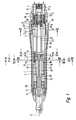
- FIG. 9 shows an external perspective view of the grinding device according to the invention. It is about 15 cm long.
- this grinding device has a housing 1, which is covered with a rubber hose 2.
- a connection body 3 on the right by means of thread 4 screwed.
- a pressure ring 5 by means of Thread 6 screwed in.
- the remaining parts are arranged and against each other tense, unless otherwise stated below is described.
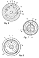
- the connector body 3 is a Air supply duct 7 and air discharge ducts 8, 8 '(cf. also Figure 6).
- the pipe body 13 is screwed into the connector body 3, which has the shoulder 9 mentioned.
- a switching ring 14 On the connector body 3 is a switching ring 14, the outside is provided with a corrugation 15, limited rotation arranged.
- the limited rotatability results in that a pin 16 is arranged in the connector body 3 is, which protrudes into a cutout 17 in the switching ring 14 (see Figure 6).
- This cutout 17 in the switching ring 14 is limited over an angular range of approximately 90 ° and thus also limits the rotation of the switching ring 14 opposite the pin arranged on the connector body 3 16th
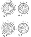
- the air duct section 22 is in one Air guide ring 23. This presses, as a result of the already mentioned screwing, on the bearing ring 24 ( Figure 3), an air distribution disk 50 ( Figure 8), the stator 25 and another bearing ring 26 is located in the stator 25 rotatable a sleeve 30.
- a ball bearing 27 is located in the bearing ring 24 are located between bearing ring 26 and pressure ring 5 Ball bearing 28, which is supported radially on the outside of the housing 1 are.
- a slide bearing is also located in the bearing ring 26 29th
- the means of the ball bearings 27, 28 and slide bearing 26 in Housing 40 is rotatably mounted rotor, as from FIG. 7 can be seen, provided with radially extending slots 41, in which rotor slide 42 is arranged to be radially displaceable are. Their radially outer end lies on the Inner surface of the sleeve 30. When rotor 40 rotates by centrifugal force they are in contact with the Sleeve 30 pressed outwards.
- the sleeve 30 eccentric with respect to the axis of rotation A (see FIG. 1) of the rotor 40 arranged in the stator 25, so that when rotating of the rotor 40, the rotor slide 42 once per revolution and be pushed here.
- the crescent-shaped pressure chamber 45 Between rotor 40 and the sleeve 30 is the crescent-shaped pressure chamber 45. In this If the compressed air enters, it hits the rotor slide 42 and thus rotates the rotor 40.
- the supply of compressed air from the air duct section 22 to the Pressure space 45 takes place, as can be seen from FIG. 2, via a annular recess 46 in the air guide ring 23 and one radially from this outgoing air duct 47, which, as can be seen from FIG. 3, into an inlet air duct 48 opens in the bearing ring 24.
- This supply air duct 48 in the bearing ring 24 extends to the left end of the bearing ring 24 ( Figure 1).
- the supply air duct 48 then opens out as if 5 can be seen in a kidney-shaped recess 49 in the air distribution disk 50, from which the transfer of the Compressed air takes place in the pressure chamber 45.
- the Air distribution disk 50, the sleeve 30 and the bearing ring 24 are secured against rotation by means of a pin 51.
- FIG. 7 and FIG. 8 the compressed air comes out of the recess 49 in the air distribution disk 50 from the top right (in FIG. 7) in the pressure chamber 45. From this point it expands the pressure space 45 in the circumferential direction. This will affect the Rotor slide 42 exerted a force in the direction of rotation, the the rotor 40 in a clockwise rotation ( Figure 7).
- the air outlet from the pressure chamber 45 takes place - see figure 5 and FIG. 7 - through the kidney-shaped recess 52 in the air distribution disk 50, which is slightly less than the left half of the pressure space 45 extends. From there the compressed air - now as exhaust air - enters the recess 53 in the bearing ring 24 (see FIG. 4) and from there into the Recess 54 in the air guide ring 23 (see FIG. 2). From there it enters room 55 on the outside of the Lucasleitrings 23 ( Figure 1) and from there into the Air discharge channels 8, in which insulating materials 60 for Noise and vibration damping are provided.
- the sleeve is made 30 made of a material that is essentially phenolic resin, Has cotton fabric and an additive molybdenum sulfide. Such a material is, for example, under the brand DURATEX commercially available.
- the rotor slides are off a material that is also made of cotton fabric and Phenolic resin is made, for example, under the brand Ferrozell HGW FF5964 is commercially available.
- FIGS. 10 to 12 show a further embodiment the air-bearing sleeve.
- the sleeve 80 shown there can advantageously in place of the sleeve 30 use Find. It has a groove 81 on the inside, for example 1 - 2.0 mm wide and 0.05 - 0.15 mm deep.
- the Side surfaces 82 are flattened and have opposite Groove base 83 an angle of 20 - 30 °. You can also get one Groove with circular segment-shaped cross-section with a similar one Provide width and depth.
- This training has the following advantage: Grinder, the rotor slide 42 through the Centrifugal forces pushed radially outwards.
- the one Rotor slide 42 which just runs past the groove 80, is pressed into the groove and then meets the in Direction of rotation lying in front of him side surface 82 this rotor slide 42 in addition to the frictional force a driving force in the direction of rotation via this side surface the sleeve 80, so that the sleeve 80 runs up to faster operating speed.
- the flattening of the side surfaces 82 allows at the beginning also when a rotor slide hits the Side surface 82 that the rotor slide when the sleeve not running at full speed yet, too emerge from the groove and overflow it, so can overtake as it were. That way Damage to the rotor slide and / or the groove avoided. After some such temporary contacts that but at least exert a force on the sleeve, it happens then to ensure that the sleeve runs fully with it. It depends on indicates that the rotor slide 42 in the direction of rotation at least one edge (formed by one of the Side surfaces 82 of the groove 81) can strike. if the Difference in the speeds of the sleeve and rotor slide is still too big, overflow or run over the Rotor slide this side surface. this will possible without damage because of the side surfaces are flattened.
- the accelerated start of the sleeve 80 also causes that it reaches the state of being on the Air film between the stator 25 and sleeve 30 is air-borne. Therefore, there is less friction overall. Therefore it is possible to do without oil tempering and the sleeve to temper only with air. This is procedurally one Simplification and leads to a reduction in Pollution from abrasion.
Landscapes
- Engineering & Computer Science (AREA)
- Mechanical Engineering (AREA)
- General Engineering & Computer Science (AREA)
- Dental Tools And Instruments Or Auxiliary Dental Instruments (AREA)
- Sliding-Contact Bearings (AREA)
Abstract
Description
- Figur 1
- einen Querschnitt durch ein Ausführungsbeispiel;
- Figur 2
- einen Schnitt in Richtung der Pfeile II-II in Figur 1;
- Figur 3
- einen Schnitt in Richtung der Pfeile III-III in Figur 1;
- Figur 4
- einen Schnitt entlang der Pfeile IV-IV in Figur 1;
- Figur 5
- einen Schnitt entlang der Pfeile V-V in Figur 1;
- Figur 6
- einen Schnitt entlang der Pfeile VI-VI in Figur 1;
- Figur 7
- einen Schnitt entlang der Pfeile VII-VII in Figur 1;
- Figur 8
- einen Schnitt entlang der Pfeile VIII-VIII in Figur 1;
- Figur 9
- eine perspektivische Außenansicht des Handschleifgerätes;
- Figur 10
- eine Vorderansicht einer modifizierten Form der luftgelagerten Hülse;
- Figur 11
- das bei XI in Figur 10 angegebene Detail;
- Figur 12
- einen Schnitt entlang der Pfeile XII-XII in Figur 10.
Claims (8)
- Mit Druckluft betriebenes Schleifgerät mit einem Rotor (40), der Schlitze (41) aufweist, in denen Rotorschieber (42) radial verschiebbar sind, wobei der Rotor (40) mit den Rotorschiebern (42) in einer gegenüber der Drehachse (A) des Rotors (40) exzentrisch angeordneten Hülse (30) drehbar sind, und die Hülse (30) in einem Stator (25) mittels eines Luftspalts (70) luftgelagert ist und durch Reibung der äußeren Endflächen der Rotorschieber (42) an der Innenwandung der Hülse (30, 80) in Drehrichtung von den Rotorschiebern (42) mitgenommen wird, dadurch gekennzeichnet, dass die Innenwandung der Hülse (30, 80) und die radial äußeren Flächen der Rotorschieber (42) aufgeraut sind, und außerdem die Rotorschieber (42) und die Hülse (30) aus einem Material bestehen, das als wesentliche Bestandteile Phenolharz und Baumwollgewebe, insbesondere mit einem Zusatz Molybdänsulfid, enthält.
- Schleifgerät nach Anspruch 1 oder 2, dadurch gekennzeichnet, dass die Oberflächengüte der Hülse (30, 80) innen Ra = 5 bis 10, vorzugsweise 5,5 bis 7,0 und die Oberflächengüte der radial äußeren Flächen der Rotorschieber Ra = 2 bis 5, vorzugsweise 3 bis 4 beträgt.
- Schleifgerät nach einem der Ansprüche 1 - 3, dadurch gekennzeichnet, dass die Oberflächengüte der Hülse (30, 80) außen Ra = 0,5 bis 1,0 beträgt.
- Schleifgerät nach einem der Ansprüche 1 - 3, dadurch gekennzeichnet, dass Hülse (30) und Rotorschieber (42) cirka 1 h in Öl getaucht und anschließend nach ca. 30 min Abtropfen bei einer Temperatur von 70 ° bis 100 °, vorzugsweise 80 °, für die Dauer von 4 bis 6 h, vorzugsweise ca. 5 h getempert werden.
- Schleifgerät nach einem der Ansprüche 1 - 3, dadurch gekennzeichnet, dass die Hülse (80) innen mindestens eine Kante (82) aufweist, auf die die Rotorschieber (42) beim Anlaufen des Schleifgerätes auftreffen.
- Schleifgerät nach Anspruch 5, dadurch gekennzeichnet, dass die Innenfläche der Hülse (80) eine Nut (81) aufweist, deren Seitenflächen je eine Kante (82) bilden.
- Schleifgerät nach Anspruch 6, dadurch gekennzeichnet, dass die Kante (82) abgeflacht ist.
- Schleifgerät nach Anspruch 5 - 7, dadurch gekennzeichnet, dass Hülse (80) und Rotorschieber (42) bei einer Temperatur von 70° bis 100°, vorzugsweise 80°, für die Dauer von 4 bis 6 h, vorzugsweise ca. 5 h, in Luft getempert sind.
Applications Claiming Priority (2)
| Application Number | Priority Date | Filing Date | Title |
|---|---|---|---|
| DE10310863A DE10310863B3 (de) | 2003-03-11 | 2003-03-11 | Schleifgerät |
| DE10310863 | 2003-03-11 |
Publications (1)
| Publication Number | Publication Date |
|---|---|
| EP1457680A1 true EP1457680A1 (de) | 2004-09-15 |
Family
ID=32748211
Family Applications (1)
| Application Number | Title | Priority Date | Filing Date |
|---|---|---|---|
| EP04005496A Withdrawn EP1457680A1 (de) | 2003-03-11 | 2004-03-08 | Schleifgerät angetrieben mittels eines Druckluftflügelmotors |
Country Status (2)
| Country | Link |
|---|---|
| EP (1) | EP1457680A1 (de) |
| DE (1) | DE10310863B3 (de) |
Cited By (1)
| Publication number | Priority date | Publication date | Assignee | Title |
|---|---|---|---|---|
| WO2007010375A1 (de) * | 2005-07-22 | 2007-01-25 | Rotomed Ag | Mikro-druckluftmotor |
Citations (6)
| Publication number | Priority date | Publication date | Assignee | Title |
|---|---|---|---|---|
| EP0022103A1 (de) * | 1979-06-15 | 1981-01-07 | Institut Cerac S.A. | Flügeldrehkolbenmaschine |
| JPS59213987A (ja) * | 1983-05-20 | 1984-12-03 | Nippon Piston Ring Co Ltd | 回転圧縮機 |
| JPS59215991A (ja) * | 1983-05-21 | 1984-12-05 | Nippon Piston Ring Co Ltd | 回転圧縮機 |
| JPS61178591A (ja) * | 1985-01-31 | 1986-08-11 | Aisin Seiki Co Ltd | ベ−ンポンプの回転スリ−ブ |
| DE4331964A1 (de) * | 1993-09-21 | 1994-04-07 | Katharina Koterewa | Trockenlaufende Gleitschiebervakuumpumpe |
| WO2003067032A1 (de) * | 2002-02-05 | 2003-08-14 | Kmb Feinmechanik Ag | Druckluftmotor |
Family Cites Families (2)
| Publication number | Priority date | Publication date | Assignee | Title |
|---|---|---|---|---|
| US3753469A (en) * | 1969-07-15 | 1973-08-21 | H Tuttle | Air tool |
| DE3913908A1 (de) * | 1989-04-27 | 1990-10-31 | Schmid & Wezel | Druckluftlamellenmotor |
-
2003
- 2003-03-11 DE DE10310863A patent/DE10310863B3/de not_active Expired - Fee Related
-
2004
- 2004-03-08 EP EP04005496A patent/EP1457680A1/de not_active Withdrawn
Patent Citations (6)
| Publication number | Priority date | Publication date | Assignee | Title |
|---|---|---|---|---|
| EP0022103A1 (de) * | 1979-06-15 | 1981-01-07 | Institut Cerac S.A. | Flügeldrehkolbenmaschine |
| JPS59213987A (ja) * | 1983-05-20 | 1984-12-03 | Nippon Piston Ring Co Ltd | 回転圧縮機 |
| JPS59215991A (ja) * | 1983-05-21 | 1984-12-05 | Nippon Piston Ring Co Ltd | 回転圧縮機 |
| JPS61178591A (ja) * | 1985-01-31 | 1986-08-11 | Aisin Seiki Co Ltd | ベ−ンポンプの回転スリ−ブ |
| DE4331964A1 (de) * | 1993-09-21 | 1994-04-07 | Katharina Koterewa | Trockenlaufende Gleitschiebervakuumpumpe |
| WO2003067032A1 (de) * | 2002-02-05 | 2003-08-14 | Kmb Feinmechanik Ag | Druckluftmotor |
Non-Patent Citations (3)
| Title |
|---|
| PATENT ABSTRACTS OF JAPAN vol. 0090, no. 87 (M - 372) 17 April 1985 (1985-04-17) * |
| PATENT ABSTRACTS OF JAPAN vol. 0090, no. 92 (M - 373) 20 April 1985 (1985-04-20) * |
| PATENT ABSTRACTS OF JAPAN vol. 0103, no. 88 (M - 549) 25 December 1986 (1986-12-25) * |
Cited By (1)
| Publication number | Priority date | Publication date | Assignee | Title |
|---|---|---|---|---|
| WO2007010375A1 (de) * | 2005-07-22 | 2007-01-25 | Rotomed Ag | Mikro-druckluftmotor |
Also Published As
| Publication number | Publication date |
|---|---|
| DE10310863B3 (de) | 2004-10-28 |
Similar Documents
| Publication | Publication Date | Title |
|---|---|---|
| DE2621485A1 (de) | Pneumatischer lamellenmotor | |
| DE3014519A1 (de) | Drehkolbenmaschine, insbesondere zellenpumpe | |
| DE3800324A1 (de) | Fluegelzellenverdichter | |
| DE102010012024B4 (de) | Handwerkzeugmaschine mit einem Zwangsrotation-Exzentergetriebe | |
| CH618235A5 (de) | ||
| DE2246901A1 (de) | Von fluid durchstroemte fluegelzellenmaschine | |
| DE3913908A1 (de) | Druckluftlamellenmotor | |
| DE102011011384B4 (de) | Hand-Werkzeugmaschine mit einem Lamellenmotor aus einem Nicht-Metall | |
| DE102004034921B9 (de) | Einflügelvakuumpumpe | |
| DE2710734B2 (de) | Verdichteraggregat, bestehend aus einem Antriebsmotor und einem Verdichter mit exzentrisch geführten, frei beweglichen Kolben | |
| DE19834033A1 (de) | Vakuumpumpe | |
| EP1457680A1 (de) | Schleifgerät angetrieben mittels eines Druckluftflügelmotors | |
| DE102010012023A1 (de) | Hand-Werkzeugmaschine mit einem Teller-Werkzeug | |
| DE7534297U (de) | Druckmittelgeraet | |
| EP0081659A1 (de) | Elektromotorisch angetriebenes Pumpaggregat | |
| DE2654991C3 (de) | Drehschieberkompressor | |
| DE2852349C2 (de) | Strömungsvibrator | |
| EP1129819A1 (de) | Lagerung eines Getriebeelements in einem Gehäuse | |
| DE3343520A1 (de) | Fluegelzellenverdichter mit variabler foerdermenge | |
| DE2313059C3 (de) | ||
| EP1272737B1 (de) | Luftmotor | |
| EP1118773A2 (de) | Flügelzellenpumpe oder Flügelzellenmotor | |
| DE1116975B (de) | Drehkolbenpumpe | |
| DE3144572A1 (de) | Drehkolbenverdichter mit verzahntem innen- und aussenlaeufer | |
| DE2940397A1 (de) | Fluegelzellenmaschine, insbesondere druckluftmotor |
Legal Events
| Date | Code | Title | Description |
|---|---|---|---|
| PUAI | Public reference made under article 153(3) epc to a published international application that has entered the european phase |
Free format text: ORIGINAL CODE: 0009012 |
|
| AK | Designated contracting states |
Kind code of ref document: A1 Designated state(s): AT BE BG CH CY CZ DE DK EE ES FI FR GB GR HU IE IT LI LU MC NL PL PT RO SE SI SK TR |
|
| AX | Request for extension of the european patent |
Extension state: AL LT LV MK |
|
| 17P | Request for examination filed |
Effective date: 20040928 |
|
| AKX | Designation fees paid |
Designated state(s): AT BE BG CH CY CZ DE DK EE ES FI FR GB GR HU IE IT LI LU MC NL PL PT RO SE SI SK TR |
|
| GRAP | Despatch of communication of intention to grant a patent |
Free format text: ORIGINAL CODE: EPIDOSNIGR1 |
|
| STAA | Information on the status of an ep patent application or granted ep patent |
Free format text: STATUS: THE APPLICATION IS DEEMED TO BE WITHDRAWN |
|
| 18D | Application deemed to be withdrawn |
Effective date: 20070908 |