EP1457617A1 - Eine Verbindungsanordnung für eine Gitterstruktur - Google Patents
Eine Verbindungsanordnung für eine Gitterstruktur Download PDFInfo
- Publication number
- EP1457617A1 EP1457617A1 EP03005725A EP03005725A EP1457617A1 EP 1457617 A1 EP1457617 A1 EP 1457617A1 EP 03005725 A EP03005725 A EP 03005725A EP 03005725 A EP03005725 A EP 03005725A EP 1457617 A1 EP1457617 A1 EP 1457617A1
- Authority
- EP
- European Patent Office
- Prior art keywords
- assembly
- elements
- elongate
- another
- diameter
- Prior art date
- Legal status (The legal status is an assumption and is not a legal conclusion. Google has not performed a legal analysis and makes no representation as to the accuracy of the status listed.)
- Granted
Links
Images


Classifications
-
- E—FIXED CONSTRUCTIONS
- E04—BUILDING
- E04C—STRUCTURAL ELEMENTS; BUILDING MATERIALS
- E04C2/00—Building elements of relatively thin form for the construction of parts of buildings, e.g. sheet materials, slabs, or panels
- E04C2/30—Building elements of relatively thin form for the construction of parts of buildings, e.g. sheet materials, slabs, or panels characterised by the shape or structure
- E04C2/42—Gratings; Grid-like panels
- E04C2/421—Gratings; Grid-like panels made of bar-like elements, e.g. bars discontinuous in one direction
- E04C2/422—Gratings; Grid-like panels made of bar-like elements, e.g. bars discontinuous in one direction with continuous bars connecting at crossing points of the grid pattern
- E04C2/425—Gratings; Grid-like panels made of bar-like elements, e.g. bars discontinuous in one direction with continuous bars connecting at crossing points of the grid pattern made of perforated bars
-
- B—PERFORMING OPERATIONS; TRANSPORTING
- B21—MECHANICAL METAL-WORKING WITHOUT ESSENTIALLY REMOVING MATERIAL; PUNCHING METAL
- B21D—WORKING OR PROCESSING OF SHEET METAL OR METAL TUBES, RODS OR PROFILES WITHOUT ESSENTIALLY REMOVING MATERIAL; PUNCHING METAL
- B21D47/00—Making rigid structural elements or units, e.g. honeycomb structures
- B21D47/005—Making gratings
Definitions
- connection assembly for a grid structure in which two elongate elements are connected at an intersection and also to a grid structure formed from such connection assemblies.
- Such structures can be used in various commercial applications but have particular relevance to pallet containers wherein an inner plastic container suitable for transporting liquid substances is enclosed by an outer supporting container comprising such a grid structures.
- pallet containers When used industrially, such pallet containers have to pass governmental approval inspections and fulfill certain criteria. For example, the filled pallet containers have to undergo interior pressure tests and drop tests from specific heights, which are also conducted at extremely low temperatures. The worst case drop is a diagonal drop onto the lower front wall of the pallet container where the bottom valve from the inner plastic receptacle is located.
- vibration test Another important criterion for governmental approval is the so-called vibration test. To simulate transport vibrations by road or rail the filled pallet containers have to undergo low frequency vibrations for a certain amount of time.
- European patent EP-A-0 916 777 discloses a connection assembly wherein first and second elongated elements are connected by providing a receiving opening in the first element through which the second element is passed, the two elements then being connected to one another at one or more positions in the region of their intersection.
- the inner plastic receptacle tends to become displaced relative to the bottom pallet and as a result of the kinetic energy generated in impact, especially at the front impact wall and the adjacent lateral surrounding areas, the hollow bars of the grid structure tend to be severely deformed. This is especially true at the cross connections of the grid structure, as the elongate element with the receiving opening is more vulnerable.
- the thin-walled plastic receptacle can be damaged by the deformed and buckled receiving opening.
- connection assembly for a grid structure which overcomes or substantially mitigates the aforementioned problems when applied to used in a grid structure for a pallet container of the type described.
- connection assembly comprising first and second elongate elements connected to one another at an intersection, the first element comprising a tube and defining at least one receiving opening through which the second element is passed, and characterised in that the portion of the first element defining the periphery of the receiving opening protrudes inwards into the tube to define a collar surrounding the second element.
- the first element defines two aligned receiving openings through which the second element is passed, the portions of the first element defining the peripheries of both of the receiving openings protruding inwards into the tube to define two collars surrounding the second element.
- an inner dimension of the or of each collar is dimensioned with respect to an outer dimension of the second element so as to provide a frictional fit of the two elements.
- the first element is drilled to define the receiving opening, the diameter of the drilled aperture being less than the diameter of the second elongate element. Thereafter, the drilled aperture is preferably punched to deform the periphery of the aperture so that it is folded inwards into the tube to form the collar and to increase the diameter of the aperture to that of the receiving opening.
- the inner surface of the first element is provided with at least one ridge, the apex of which lies close to or contacts the outer surface of the second element, at which position or positions the first and second elongate elements may be connected to one another.
- first and second elongate elements are made of metal they may be connected to one another at said one or more positions by welding.
- the first and second elongate elements are made of a plastics material, they may be connected to one another by ultrasonic welding, induction welding or melt bonding.
- the first elongate element is tubular with a substantially circular, elliptical or ovoid cross-section.
- the second elongate element may also be tubular with a substantially circular or oval cross-section.
- the diameter of the second element is smaller by between 20% to 30% than the diameter of the first element.
- a grid structure comprising a plurality of first elongate, tubular elements arranged in parallel and in a spaced relationship with respect to one another, a plurality of second elongate elements arranged in parallel and in a spaced relationship with respect to one another, the first and second elements intersecting and being connected to one another by means of at least one connection assembly in accordance with the first aspect of the present invention.
- a grid structure 1 comprises a plurality of first elongate, tubular elements 2 arranged in parallel in a spaced relationship with respect to one another and a plurality of second elongate elements 3, which are also arranged in parallel in a spaced relationship with respect to one another.
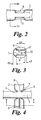
- the first and second elements 2 and 3 are connected together at each intersection 4 of the structure 1 via a connection assembly 5 as will now be described with reference to Figs. 2 to 5.
- the first tubular element 2 defines two aligned receiving openings 6 through which the second element 3 is passed.
- the portion of the first element 2 defining the periphery of each opening 6 protrudes inwards into the interior of the tube to define a collar 7 that surrounds the second element 3.
- the diameter d2 of the second element 3 is smaller than the diameter d1 of the first element 2, preferably by between 20% to 30%.
- the diameter d1 of the first element 2 could be 22 mm and the diameter d2 of the second element 3 could be 16 mm.
- first and second elements, 2 and 3 may both have a circular cross-section
- other constructions are possible wherein the cross-sectional shape of one or both of the elements 2 and 3 is not circular but elliptical or ovoid.
- the second element 3 has a circular cross-section but the first element 2 has a cross sectional shape that is elliptical, d1 being the length of the major axis.
- the first element 2 is always tubular
- the second element 3 can be either of tubular or of solid construction.
- intersections 4 shown in Fig. 1 and in Figs. 2 to 5 the first and second elements 2 and 3 cross so that two openings 6 are required in the tubular structure of the first element 2 to permit the second element 3 to pass completely therethrough.
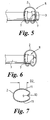
- T-shaped intersections 8 can be formed wherein the first element 2 is only provided with one receiving opening 6 and the second element 3 terminates within the tubular structure of the first element 2 after passing through the single opening 6. Such an arrangement is shown in Fig. 6.
- the inner dimension of the receiving opening 6 formed in the first element 2 is sized with respect to the outer dimension of the second element 2 such that there is no play between the collar 7 and the second element 2.
- the second element 2 is then inserted through the opening 6 under the application of force to overcome friction between the outer surface of the second element 2 and the inner face of the collar 7. In this manner a non-positive frictional fit is established between the first and second elements 2 and 3 which adds to the mechanical strength of the connection assembly, particularly against bending moments which may arise under load in the plane of the two elements 2 and 3.
- the first element 2 may comprise an inner ridge 9, the apex of which is arranged to lie close to or to contact the outer surface of the second element 2 at a position P1.
- a second, identical ridge could also be provided on the opposite side of the first element 2.
- the ridge 9 can be formed when making the element 2 by externally applying pressure to form a longitudinal crease or indentation 10.
- the indentation 10 could be formed only in the regions of the intersections 4 of the two elements 2 and 3.
- An internal ridge 9 could also be formed within the tubular structure of the first element during its production process whereby the outer diameter of the element 2 tube would remain substantially circular or elliptical, without any significant external indentation 10 being visible.
- the two elements 2 and 3 may be connected to one another at this point.
- Such a connection may be performed by resistance welding for metallic elements 2 and 3 or alternatively by ultrasonic welding, induction welding or melt bonding if the elements 2 and 3 are made of a plastics material.
- the openings 6 in the first element 2 can be made by drilling and punching operations as will now be described.
- an aperture 11 is drilled into the tubular structure of the first element 2, as shown in Fig. 7, for example using flow drill technology.
- the diameter D2 of the aperture 11 is made less than the diameter D3 of the required receiving opening 6 and is typically less than the diameter d2 of the second element 3.
- a punch is then used to deform the periphery of the aperture 11 so that it is folded inwards into the tubular structure of the first element 2 to form the inwardly protruding collar 7 and to increase the diameter of the aperture 11 to a required diameter D3.
- the high speed drill heats the metal around the hole so that it can be readily deformed inwardly by a subsequent punching operation to form the collar 7.
- the shape of the aperture 11 and the cross-sectional shape of the punch should be similar to that of the second element 3, and typically are either circular or elliptical.
- the collar 7 of the present invention reduces the likelihood of breakage of both the first and second elements 2 at the intersections 4 for two reasons. First, if the second element 3 is pushed out of an alignment perpendicular to the first element 2, as shown in Fig. 8, then the collar 7 supports the second element 3 and provides a smooth pivot surface about which the second element 3 can bend rather than the sharp 'knife edge' pivot points provided by the rim of the aperture 13 of the element 12 of the prior art arrangement, as shown in Fig. 10.
- each collar 7 spreads the dynamic forces which occur between the first and second elongate elements 2 and 3 over its surface area so that there are no "knife edge" contacts between the elements 2 and 3.
- the inwardly protruding collars 7 strengthen the grid structure, reduce bulging and make it more rigid so that it provides a stronger support casing for the thin-walled inner container.
- the first and second elongate elements bend inwards and outwards owing to the vibrations applied thereto and the present invention again reduces the likelihood of stress cracking and stress fractures occurring for the same reasons as indicated above.
- the present invention provides a connection assembly and therefore a grid structure which is more able to withstand the strains and stresses imposed on it during testing and use than prior arrangements.
- the present invention therefore provides a greater security to the carried load.
Landscapes
- Engineering & Computer Science (AREA)
- Architecture (AREA)
- Civil Engineering (AREA)
- Structural Engineering (AREA)
- Mechanical Engineering (AREA)
- Pallets (AREA)
- Mutual Connection Of Rods And Tubes (AREA)
- Road Paving Structures (AREA)
- Orthopedics, Nursing, And Contraception (AREA)
- Finger-Pressure Massage (AREA)
Priority Applications (5)
| Application Number | Priority Date | Filing Date | Title |
|---|---|---|---|
| ES03005725T ES2307844T3 (es) | 2003-03-13 | 2003-03-13 | Estructura de enrejado. |
| EP03005725A EP1457617B1 (de) | 2003-03-13 | 2003-03-13 | Eine Gitterstruktur |
| AT03005725T ATE395478T1 (de) | 2003-03-13 | 2003-03-13 | Eine gitterstruktur |
| DE60320929T DE60320929D1 (de) | 2003-03-13 | 2003-03-13 | Eine Gitterstruktur |
| US10/800,391 US20050001129A1 (en) | 2003-03-13 | 2004-03-12 | Connection assembly for a grid structure |
Applications Claiming Priority (1)
| Application Number | Priority Date | Filing Date | Title |
|---|---|---|---|
| EP03005725A EP1457617B1 (de) | 2003-03-13 | 2003-03-13 | Eine Gitterstruktur |
Publications (2)
| Publication Number | Publication Date |
|---|---|
| EP1457617A1 true EP1457617A1 (de) | 2004-09-15 |
| EP1457617B1 EP1457617B1 (de) | 2008-05-14 |
Family
ID=32748882
Family Applications (1)
| Application Number | Title | Priority Date | Filing Date |
|---|---|---|---|
| EP03005725A Expired - Lifetime EP1457617B1 (de) | 2003-03-13 | 2003-03-13 | Eine Gitterstruktur |
Country Status (5)
| Country | Link |
|---|---|
| US (1) | US20050001129A1 (de) |
| EP (1) | EP1457617B1 (de) |
| AT (1) | ATE395478T1 (de) |
| DE (1) | DE60320929D1 (de) |
| ES (1) | ES2307844T3 (de) |
Cited By (1)
| Publication number | Priority date | Publication date | Assignee | Title |
|---|---|---|---|---|
| EP1779940A1 (de) * | 2005-10-27 | 2007-05-02 | Etablissements Primet | Verfahren zum Hertsellen von metallischen geflechteten Strukturen sowie durch das Verfahren hergestellte Strukture |
Families Citing this family (2)
| Publication number | Priority date | Publication date | Assignee | Title |
|---|---|---|---|---|
| US8403284B2 (en) * | 2008-06-27 | 2013-03-26 | Jon Korbonski | Pallet assembly |
| US20170321964A1 (en) * | 2016-05-03 | 2017-11-09 | Saint-Gobain Ceramics & Plastics, Inc. | High temperature ceramic support rack |
Citations (4)
| Publication number | Priority date | Publication date | Assignee | Title |
|---|---|---|---|---|
| US2067945A (en) * | 1935-06-10 | 1937-01-19 | Herman J Peters | Method of forming tube connections |
| US3068029A (en) * | 1959-12-21 | 1962-12-11 | Schwartz Metal Company Inc | Structural assembly |
| FR2472072A1 (fr) * | 1979-12-21 | 1981-06-26 | Gubri Sa Ets L | Perfectionnements apportes aux articles ou produits du genre des echelles et a leurs procedes de fabrication |
| EP0916777A1 (de) | 1997-11-04 | 1999-05-19 | Royal Packaging Industries Van Leer N.V. | Verbindungszusammenbau |
Family Cites Families (11)
| Publication number | Priority date | Publication date | Assignee | Title |
|---|---|---|---|---|
| US548998A (en) * | 1895-10-29 | Tubular-rail joint | ||
| US3068026A (en) * | 1958-06-13 | 1962-12-11 | Gen Motors Corp | Cryogenic fluid transfer line coupling |
| US3429033A (en) * | 1965-02-19 | 1969-02-25 | Rca Corp | Method of securing a rod to a supporting structure |
| US3344370A (en) * | 1965-06-03 | 1967-09-26 | Dielectric Products Engineerin | Coaxial transmission lines |
| US4202484A (en) * | 1978-11-20 | 1980-05-13 | Conoco, Inc. | Compression prestressed weld joints |
| CA1146092A (en) * | 1979-10-11 | 1983-05-10 | Terence B.F. Cottrell | Non-welded discharge electrode |
| US4776719A (en) * | 1987-11-09 | 1988-10-11 | Kreider Jeff A | Tubular structural system |
| US5517744A (en) * | 1994-11-04 | 1996-05-21 | Cosco, Inc. | Press-fit tube-connection system |
| FR2757788B1 (fr) * | 1996-12-31 | 1999-03-12 | Vallourec Vitry | Procede pour l'emmanchement en croix d'une piece cylindrique dans une piece tubulaire, outillage propre a sa mise en oeuvre, et ensemble de deux pieces correspondant |
| US6688803B2 (en) * | 1999-12-23 | 2004-02-10 | Royal Packaging Industries Van Leer N.V. | Connection assembly |
| US6758360B2 (en) * | 1999-12-23 | 2004-07-06 | Royal Packaging Industry Leer N.V. | Pallet container with grid support structure |
-
2003
- 2003-03-13 ES ES03005725T patent/ES2307844T3/es not_active Expired - Lifetime
- 2003-03-13 AT AT03005725T patent/ATE395478T1/de not_active IP Right Cessation
- 2003-03-13 EP EP03005725A patent/EP1457617B1/de not_active Expired - Lifetime
- 2003-03-13 DE DE60320929T patent/DE60320929D1/de not_active Expired - Lifetime
-
2004
- 2004-03-12 US US10/800,391 patent/US20050001129A1/en not_active Abandoned
Patent Citations (4)
| Publication number | Priority date | Publication date | Assignee | Title |
|---|---|---|---|---|
| US2067945A (en) * | 1935-06-10 | 1937-01-19 | Herman J Peters | Method of forming tube connections |
| US3068029A (en) * | 1959-12-21 | 1962-12-11 | Schwartz Metal Company Inc | Structural assembly |
| FR2472072A1 (fr) * | 1979-12-21 | 1981-06-26 | Gubri Sa Ets L | Perfectionnements apportes aux articles ou produits du genre des echelles et a leurs procedes de fabrication |
| EP0916777A1 (de) | 1997-11-04 | 1999-05-19 | Royal Packaging Industries Van Leer N.V. | Verbindungszusammenbau |
Cited By (2)
| Publication number | Priority date | Publication date | Assignee | Title |
|---|---|---|---|---|
| EP1779940A1 (de) * | 2005-10-27 | 2007-05-02 | Etablissements Primet | Verfahren zum Hertsellen von metallischen geflechteten Strukturen sowie durch das Verfahren hergestellte Strukture |
| FR2892649A1 (fr) * | 2005-10-27 | 2007-05-04 | Primet Sarl Ets | Procede de fabrication de structures en metal tresse et les produits obtenus selon le procede |
Also Published As
| Publication number | Publication date |
|---|---|
| ATE395478T1 (de) | 2008-05-15 |
| EP1457617B1 (de) | 2008-05-14 |
| US20050001129A1 (en) | 2005-01-06 |
| ES2307844T3 (es) | 2008-12-01 |
| DE60320929D1 (de) | 2008-06-26 |
Similar Documents
| Publication | Publication Date | Title |
|---|---|---|
| JP5496211B2 (ja) | パレットコンテナ | |
| JP4562677B2 (ja) | 溶接構造閉断面フレーム | |
| US7140490B2 (en) | Pallet container | |
| US20020008108A1 (en) | Pallet container with grid support structure | |
| EP1457617B1 (de) | Eine Gitterstruktur | |
| EP0916592B1 (de) | Palettenbehälter mit Gittertragstruktur | |
| US6688803B2 (en) | Connection assembly | |
| CA2409852C (en) | Pallet container | |
| KR100776772B1 (ko) | 팔레트 컨테이너 | |
| EP0040277B1 (de) | Leicht zu öffnender Dosendeckel mit einem Zugring | |
| US11235417B2 (en) | Structural member | |
| US7231745B1 (en) | Truss structure, structural members thereof, and a method of manufacture therefor | |
| JP5031643B2 (ja) | クロスメンバ及びクロスメンバユニット製造方法 | |
| JP4006848B2 (ja) | サスペンション用リンク | |
| JP2006524611A (ja) | パレットコンテナ | |
| JP6211010B2 (ja) | パレットコンテナ | |
| JP2001010421A (ja) | 車両用バンパ装置 | |
| JP4993520B2 (ja) | 溶接構造閉断面フレーム | |
| JP4825037B2 (ja) | フレーム構造 | |
| IL153019A (en) | Contents board for pipes | |
| JP2004034815A (ja) | サスペンションメンバー | |
| CN110076221A (zh) | 一种u型板成型方法及u型板安装方法 |
Legal Events
| Date | Code | Title | Description |
|---|---|---|---|
| PUAI | Public reference made under article 153(3) epc to a published international application that has entered the european phase |
Free format text: ORIGINAL CODE: 0009012 |
|
| AK | Designated contracting states |
Kind code of ref document: A1 Designated state(s): AT BE BG CH CY CZ DE DK EE ES FI FR GB GR HU IE IT LI LU MC NL PT SE SI SK TR |
|
| AX | Request for extension of the european patent |
Extension state: AL LT LV MK RO |
|
| 17P | Request for examination filed |
Effective date: 20050315 |
|
| AKX | Designation fees paid |
Designated state(s): AT BE BG CH CY CZ DE DK EE ES FI FR GB GR HU IE IT LI LU MC NL PT SE SI SK TR |
|
| 17Q | First examination report despatched |
Effective date: 20070316 |
|
| GRAP | Despatch of communication of intention to grant a patent |
Free format text: ORIGINAL CODE: EPIDOSNIGR1 |
|
| RTI1 | Title (correction) |
Free format text: A GRID STRUCTURE |
|
| GRAS | Grant fee paid |
Free format text: ORIGINAL CODE: EPIDOSNIGR3 |
|
| GRAA | (expected) grant |
Free format text: ORIGINAL CODE: 0009210 |
|
| AK | Designated contracting states |
Kind code of ref document: B1 Designated state(s): AT BE BG CH CY CZ DE DK EE ES FI FR GB GR HU IE IT LI LU MC NL PT SE SI SK TR |
|
| REG | Reference to a national code |
Ref country code: GB Ref legal event code: FG4D |
|
| REG | Reference to a national code |
Ref country code: CH Ref legal event code: EP |
|
| REG | Reference to a national code |
Ref country code: IE Ref legal event code: FG4D Free format text: LANGUAGE OF EP DOCUMENT: FRENCH |
|
| REF | Corresponds to: |
Ref document number: 60320929 Country of ref document: DE Date of ref document: 20080626 Kind code of ref document: P |
|
| PG25 | Lapsed in a contracting state [announced via postgrant information from national office to epo] |
Ref country code: SI Free format text: LAPSE BECAUSE OF FAILURE TO SUBMIT A TRANSLATION OF THE DESCRIPTION OR TO PAY THE FEE WITHIN THE PRESCRIBED TIME-LIMIT Effective date: 20080514 |
|
| PG25 | Lapsed in a contracting state [announced via postgrant information from national office to epo] |
Ref country code: FI Free format text: LAPSE BECAUSE OF FAILURE TO SUBMIT A TRANSLATION OF THE DESCRIPTION OR TO PAY THE FEE WITHIN THE PRESCRIBED TIME-LIMIT Effective date: 20080514 |
|
| PG25 | Lapsed in a contracting state [announced via postgrant information from national office to epo] |
Ref country code: AT Free format text: LAPSE BECAUSE OF FAILURE TO SUBMIT A TRANSLATION OF THE DESCRIPTION OR TO PAY THE FEE WITHIN THE PRESCRIBED TIME-LIMIT Effective date: 20080514 |
|
| REG | Reference to a national code |
Ref country code: ES Ref legal event code: FG2A Ref document number: 2307844 Country of ref document: ES Kind code of ref document: T3 |
|
| RAP2 | Party data changed (patent owner data changed or rights of a patent transferred) |
Owner name: GREIF INTERNATIONAL HOLDING BV. |
|
| PG25 | Lapsed in a contracting state [announced via postgrant information from national office to epo] |
Ref country code: DK Free format text: LAPSE BECAUSE OF FAILURE TO SUBMIT A TRANSLATION OF THE DESCRIPTION OR TO PAY THE FEE WITHIN THE PRESCRIBED TIME-LIMIT Effective date: 20080514 Ref country code: PT Free format text: LAPSE BECAUSE OF FAILURE TO SUBMIT A TRANSLATION OF THE DESCRIPTION OR TO PAY THE FEE WITHIN THE PRESCRIBED TIME-LIMIT Effective date: 20081014 Ref country code: SE Free format text: LAPSE BECAUSE OF FAILURE TO SUBMIT A TRANSLATION OF THE DESCRIPTION OR TO PAY THE FEE WITHIN THE PRESCRIBED TIME-LIMIT Effective date: 20080814 Ref country code: CZ Free format text: LAPSE BECAUSE OF FAILURE TO SUBMIT A TRANSLATION OF THE DESCRIPTION OR TO PAY THE FEE WITHIN THE PRESCRIBED TIME-LIMIT Effective date: 20080514 |
|
| PG25 | Lapsed in a contracting state [announced via postgrant information from national office to epo] |
Ref country code: SK Free format text: LAPSE BECAUSE OF FAILURE TO SUBMIT A TRANSLATION OF THE DESCRIPTION OR TO PAY THE FEE WITHIN THE PRESCRIBED TIME-LIMIT Effective date: 20080514 |
|
| PLBE | No opposition filed within time limit |
Free format text: ORIGINAL CODE: 0009261 |
|
| STAA | Information on the status of an ep patent application or granted ep patent |
Free format text: STATUS: NO OPPOSITION FILED WITHIN TIME LIMIT |
|
| 26N | No opposition filed |
Effective date: 20090217 |
|
| PG25 | Lapsed in a contracting state [announced via postgrant information from national office to epo] |
Ref country code: BG Free format text: LAPSE BECAUSE OF FAILURE TO SUBMIT A TRANSLATION OF THE DESCRIPTION OR TO PAY THE FEE WITHIN THE PRESCRIBED TIME-LIMIT Effective date: 20080814 Ref country code: EE Free format text: LAPSE BECAUSE OF FAILURE TO SUBMIT A TRANSLATION OF THE DESCRIPTION OR TO PAY THE FEE WITHIN THE PRESCRIBED TIME-LIMIT Effective date: 20080514 |
|
| PG25 | Lapsed in a contracting state [announced via postgrant information from national office to epo] |
Ref country code: MC Free format text: LAPSE BECAUSE OF NON-PAYMENT OF DUE FEES Effective date: 20090331 |
|
| REG | Reference to a national code |
Ref country code: CH Ref legal event code: PL |
|
| REG | Reference to a national code |
Ref country code: IE Ref legal event code: MM4A |
|
| PG25 | Lapsed in a contracting state [announced via postgrant information from national office to epo] |
Ref country code: LI Free format text: LAPSE BECAUSE OF NON-PAYMENT OF DUE FEES Effective date: 20090331 Ref country code: IE Free format text: LAPSE BECAUSE OF NON-PAYMENT OF DUE FEES Effective date: 20090313 Ref country code: CH Free format text: LAPSE BECAUSE OF NON-PAYMENT OF DUE FEES Effective date: 20090331 |
|
| PG25 | Lapsed in a contracting state [announced via postgrant information from national office to epo] |
Ref country code: GR Free format text: LAPSE BECAUSE OF FAILURE TO SUBMIT A TRANSLATION OF THE DESCRIPTION OR TO PAY THE FEE WITHIN THE PRESCRIBED TIME-LIMIT Effective date: 20080815 |
|
| PG25 | Lapsed in a contracting state [announced via postgrant information from national office to epo] |
Ref country code: LU Free format text: LAPSE BECAUSE OF NON-PAYMENT OF DUE FEES Effective date: 20090313 |
|
| PG25 | Lapsed in a contracting state [announced via postgrant information from national office to epo] |
Ref country code: HU Free format text: LAPSE BECAUSE OF FAILURE TO SUBMIT A TRANSLATION OF THE DESCRIPTION OR TO PAY THE FEE WITHIN THE PRESCRIBED TIME-LIMIT Effective date: 20081115 |
|
| PG25 | Lapsed in a contracting state [announced via postgrant information from national office to epo] |
Ref country code: CY Free format text: LAPSE BECAUSE OF FAILURE TO SUBMIT A TRANSLATION OF THE DESCRIPTION OR TO PAY THE FEE WITHIN THE PRESCRIBED TIME-LIMIT Effective date: 20080514 |
|
| PGFP | Annual fee paid to national office [announced via postgrant information from national office to epo] |
Ref country code: IT Payment date: 20120322 Year of fee payment: 10 |
|
| PGFP | Annual fee paid to national office [announced via postgrant information from national office to epo] |
Ref country code: ES Payment date: 20120426 Year of fee payment: 10 |
|
| PGFP | Annual fee paid to national office [announced via postgrant information from national office to epo] |
Ref country code: GB Payment date: 20130328 Year of fee payment: 11 |
|
| PGFP | Annual fee paid to national office [announced via postgrant information from national office to epo] |
Ref country code: DE Payment date: 20130529 Year of fee payment: 11 Ref country code: BE Payment date: 20130430 Year of fee payment: 11 |
|
| PGFP | Annual fee paid to national office [announced via postgrant information from national office to epo] |
Ref country code: NL Payment date: 20130322 Year of fee payment: 11 Ref country code: FR Payment date: 20130422 Year of fee payment: 11 |
|
| PG25 | Lapsed in a contracting state [announced via postgrant information from national office to epo] |
Ref country code: TR Free format text: LAPSE BECAUSE OF FAILURE TO SUBMIT A TRANSLATION OF THE DESCRIPTION OR TO PAY THE FEE WITHIN THE PRESCRIBED TIME-LIMIT Effective date: 20080514 |
|
| REG | Reference to a national code |
Ref country code: DE Ref legal event code: R119 Ref document number: 60320929 Country of ref document: DE |
|
| REG | Reference to a national code |
Ref country code: NL Ref legal event code: V1 Effective date: 20141001 |
|
| GBPC | Gb: european patent ceased through non-payment of renewal fee |
Effective date: 20140313 |
|
| REG | Reference to a national code |
Ref country code: FR Ref legal event code: ST Effective date: 20141128 |
|
| REG | Reference to a national code |
Ref country code: DE Ref legal event code: R119 Ref document number: 60320929 Country of ref document: DE Effective date: 20141001 |
|
| PG25 | Lapsed in a contracting state [announced via postgrant information from national office to epo] |
Ref country code: DE Free format text: LAPSE BECAUSE OF NON-PAYMENT OF DUE FEES Effective date: 20141001 Ref country code: FR Free format text: LAPSE BECAUSE OF NON-PAYMENT OF DUE FEES Effective date: 20140331 Ref country code: GB Free format text: LAPSE BECAUSE OF NON-PAYMENT OF DUE FEES Effective date: 20140313 |
|
| PG25 | Lapsed in a contracting state [announced via postgrant information from national office to epo] |
Ref country code: NL Free format text: LAPSE BECAUSE OF NON-PAYMENT OF DUE FEES Effective date: 20141001 |
|
| PG25 | Lapsed in a contracting state [announced via postgrant information from national office to epo] |
Ref country code: IT Free format text: LAPSE BECAUSE OF NON-PAYMENT OF DUE FEES Effective date: 20140313 |
|
| REG | Reference to a national code |
Ref country code: ES Ref legal event code: FD2A Effective date: 20150504 |
|
| PG25 | Lapsed in a contracting state [announced via postgrant information from national office to epo] |
Ref country code: ES Free format text: LAPSE BECAUSE OF NON-PAYMENT OF DUE FEES Effective date: 20140314 |
|
| PG25 | Lapsed in a contracting state [announced via postgrant information from national office to epo] |
Ref country code: BE Free format text: LAPSE BECAUSE OF NON-PAYMENT OF DUE FEES Effective date: 20140331 |