EP1455207A1 - Lichtleitkupplung - Google Patents
Lichtleitkupplung Download PDFInfo
- Publication number
- EP1455207A1 EP1455207A1 EP03010282A EP03010282A EP1455207A1 EP 1455207 A1 EP1455207 A1 EP 1455207A1 EP 03010282 A EP03010282 A EP 03010282A EP 03010282 A EP03010282 A EP 03010282A EP 1455207 A1 EP1455207 A1 EP 1455207A1
- Authority
- EP
- European Patent Office
- Prior art keywords
- light
- optical fiber
- coupling part
- signals
- coupling
- Prior art date
- Legal status (The legal status is an assumption and is not a legal conclusion. Google has not performed a legal analysis and makes no representation as to the accuracy of the status listed.)
- Granted
Links
Images


Classifications
-
- B—PERFORMING OPERATIONS; TRANSPORTING
- B60—VEHICLES IN GENERAL
- B60D—VEHICLE CONNECTIONS
- B60D1/00—Traction couplings; Hitches; Draw-gear; Towing devices
- B60D1/58—Auxiliary devices
- B60D1/62—Auxiliary devices involving supply lines, electric circuits or the like
- B60D1/64—Couplings or joints therefor
-
- B—PERFORMING OPERATIONS; TRANSPORTING
- B61—RAILWAYS
- B61G—COUPLINGS; DRAUGHT AND BUFFING APPLIANCES
- B61G5/00—Couplings for special purposes not otherwise provided for
- B61G5/06—Couplings for special purposes not otherwise provided for for, or combined with, couplings or connectors for fluid conduits or electric cables
- B61G5/10—Couplings for special purposes not otherwise provided for for, or combined with, couplings or connectors for fluid conduits or electric cables for electric cables
-
- G—PHYSICS
- G02—OPTICS
- G02B—OPTICAL ELEMENTS, SYSTEMS OR APPARATUS
- G02B6/00—Light guides; Structural details of arrangements comprising light guides and other optical elements, e.g. couplings
- G02B6/24—Coupling light guides
- G02B6/42—Coupling light guides with opto-electronic elements
- G02B6/4201—Packages, e.g. shape, construction, internal or external details
- G02B6/4204—Packages, e.g. shape, construction, internal or external details the coupling comprising intermediate optical elements, e.g. lenses, holograms
- G02B6/4206—Optical features
-
- G—PHYSICS
- G02—OPTICS
- G02B—OPTICAL ELEMENTS, SYSTEMS OR APPARATUS
- G02B6/00—Light guides; Structural details of arrangements comprising light guides and other optical elements, e.g. couplings
- G02B6/24—Coupling light guides
- G02B6/42—Coupling light guides with opto-electronic elements
- G02B6/4292—Coupling light guides with opto-electronic elements the light guide being disconnectable from the opto-electronic element, e.g. mutually self aligning arrangements
Definitions
- the present invention relates to an optical fiber coupling, in particular for Transmission of optical signals between mutually coupled vehicle parts, with a first and a second coupling part, which together can be coupled and in each of which a light-guiding element is held by which is at least one elastically biased so that the light-guiding Elements are pressed together with their end faces when the coupling parts are coupled together to transmit light from one allow light-guiding element to the other.
- the middle buffer coupling includes a cable coupling, which among other things serves, impulses for the control of the braking and driving current in a train set transfer from one car to another.
- the cable coupling consists of two contact carriers, one of which is attached to each carriage is and in which in addition to a variety of electrical contacts an optical fiber is arranged.
- One of the optical fibers is such elastically biased that the two optical fibers with their end faces pressed together when the contact carriers when coupling the car to be moved towards each other. About these pressed optical fibers optical signals can be transmitted from one car to another.
- DE 100 52 020 A1 proposed to use a conventional one in harsh conditions to completely dispense with optical coupling of optical fibers and instead the optical signals conducted in a first optical waveguide first convert it into electrical signals, using a conventional one Electric coupling to transmit, the transmitted electrical signals in turn convert into optical signals and feed into a second optical fiber.
- one foregoes the advantages of one Optical fiber coupling namely that of a higher transmission bandwidth and a lower susceptibility to electrical interference fields, the in particular always occur when in the immediate vicinity too high currents are transmitted, as is the case with cable couplings, for example is often the case for rail vehicles.
- the invention is based on the object of specifying an optical fiber coupling, which is simple in structure and interference-insensitive signal transmission allowed.
- This task is carried out in an optical fiber coupling of the type mentioned solved in that the end face of a light-guiding element is spherical concave and the end face of the other light-guiding element with the same Radius of curvature is spherically convex.
- the convex end face of one coupling part lies a perfect fit in the concave face of the other coupling part without an air gap between the end faces, which attenuates the optical Signals would result.
- the spherical end faces allow the optical to be tilted Axes of the light guiding elements against each other without the End faces are lifted from each other.
- the spherically convex face slides on the spherically concave Face along like a joint head in an acetabular cup without itself there is an air gap between the end faces.
- the possibility of low damping when the coupling parts are tilted against each other is particularly important when the optical fiber coupling for the transmission of optical signals between coupled ones Vehicle parts, for example rail vehicles.
- Vehicle parts for example rail vehicles
- the coupling parts of signal clutches and electric clutches linear i.e. prevent tilting of the coupling parts against each other.
- a linear guide can be completely dispensed with, because even relative large tilting of the coupling parts against each other to a tolerable Attenuation of the signal.
- the optical fiber coupling according to the invention is to a certain extent "kinkable".
- the light-conducting elements preferably each consist of an opaque one Sleeve and a transparent core accommodated therein. When the coupling parts are coupled, the opaque sleeves form a light tunnel shielded from daylight.
- the spherical end face of the transparent core is in each case in the sleeve end continuously continued. So even when the light-guiding elements are tilted no daylight can enter the transparent core relative to each other, the wall thickness of the sleeve in the area of the end faces must not be too small. It is advantageously at least 1/10, preferably at least 1/5 the radius of curvature of the face.
- optical fiber coupling described so far can in a conventional manner and with the described advantages as a passive coupling element between two Optical fibers are used. For example, an optical signal via a first optical fiber over a certain distance to the first coupling part are passed and fed there in its light-guiding element become. The optical signal is then through the end faces of the two light-guiding Elements on the light-guiding element of the second coupling part transmitted, fed from this into the second optical fiber and therein passed over a further distance.
- optical fiber coupling described is also suitable for one wider and more versatile use. Great versatility is achieved if the optical fiber coupling with active elements for signal processing or is equipped to generate new signals.
- the first coupling part therefore contains a transmitting device that generates optical signals from electrical signals and feeds it into the light-conducting element of the first coupling part.
- the second coupling part contains a receiving device, on the light-guiding element of the second coupling part transmitted optical signals generated electrical signals.
- the first coupling part can contain a microprocessor, which provides the electrical signals for the transmitter.
- That too second coupling part can include a microprocessor, which in the Received device processed electrical signal processed. With this processing can be checked in the microprocessor of the second coupling part, for example whether the signals have been completely transmitted. If not Should this be the case, the microprocessor of the first coupling part can be commissioned to send these signals again.
- the microprocessor of the first coupling part can, for example, the strength of the transmission device in it generating optical signals prescribe a possible attenuation the optical signal transmission due to contamination or condensation of the End faces of the light-guiding elements compensated.
- the first and / or the second coupling part preferably has a housing one axial end of which a sleeve-like section is formed, in which the light-guiding element is mounted axially displaceable and in the direction of this one axial end is resiliently biased, and at the other end Connection bolt is formed, which is intended for insertion into a contact carrier is.
- the connecting bolt preferably consists of two against each other isolated sections, one of which has a ground potential and the another is connected to an electrical signal line when the connector bolt is inserted in the contact carrier.
- Figure 1 is a longitudinal sectional view of the first coupling part 10 one Optical fiber coupling according to a development of the present invention in an exploded view (above) and in the assembled state (below).
- Figure 2 is a longitudinal sectional view of the second coupling part 12 of the same optical fiber coupling in exploded view (above) and in the assembled Condition shown (below). Because the first and the second coupling part 10 or 12 are identical in many characteristics, they are described below jointly described, the same parts by the same reference numerals be marked.
- the coupling parts 10 and 12 each have a metal housing 14 with a sleeve-like section 16, in which a light-guiding element 18 is axially displaceable is stored.
- the light-conducting elements 18 can against the biasing force a spring 20 in the sleeve-like section 16 of the respective housing 14 are pressed.
- the light-guiding Element 18 also by gas trapped in the sleeve-like section be pneumatically preloaded.
- the light-guiding elements 18 exist each made of an opaque sleeve 22 and one received therein transparent core 24.
- the light-guiding element 18 of the first coupling part has a sleeve-like Spherical concave end surface 26 facing away from housing section 16 (FIG 1) and the light-guiding element 18 of the second coupling part 12 a spherically convex end face 26 '( Figure 2), the radius of curvature of which the spherically concave end face 26 matches.
- the spherical concave end face 26 and the spherically convex end face 26 ' are not only formed in the transparent core 24, but are in the axial end of the respective sleeve 22 of the light-guiding element 18 continued continuously.
- Guide grooves 27 are formed in the sleeves 22 and guide pins 28 intervention.
- the displacement movement of the light-guiding elements 18 becomes limited in that one of the ends of the guide groove 27 on the guide pin 28 triggers.
- the interior of the sleeve-like housing section 16 consists of two cylindrical Sections, an inner section 30 and another outer section 32, the diameter of which is larger than that of the inside lying section 30. Between the cylindrical interior sections 30 and 32, a shoulder 34 is formed in the housing inner wall. Outside Interior section 32 are the light-guiding element 18 and the spring 20, which is at one end on the light-guiding element 18, with the the other end is supported on a metal ring 36, which in turn on the paragraph 34th rests.
- the inner clutch section 30 is located at the first coupling part 10 a transmitting device 38 (FIG. 1) and a receiving device in the second coupling part 40 ( Figure 2). Both the transmitter 38 and the Receiving device 40 have a ground connection 42, which with the sleeve-like Section 16 of the housing 14 is soldered, and a signal connection 44th
- the housing 14 has at its 18 facing away from the light-guiding element End a hollow connector bolt 46 with a ground connection portion 48, a signal connection section 50 and an interposed insulation piece 52 that electrically isolates sections 48 and 50 from one another.
- the Signal connection 44 is guided through the cavity in the connection bolt 46 and soldered to the signal connector 50.
- the inner interior portion 30 and the cavity of the connecting bolt 46 are filled with potting compound, which is shown by hatching in Figures 1 and 2.
- FIG. 6 is an enlarged sectional view of the housing 14 of the first Coupling part 10 shown.
- an external thread 54 is formed, with which the first coupling part 10 in a version located at ground potential can be screwed into a contact carrier.
- FIG. 6 also shows a bore 57 in which the ground connection 40 of the Transmitting device 38 is soldered.
- Figure 8 shows a cross section through the housing 14 of the first coupling part 10 along the line A-A of Figure 6.
- the sleeve-like Section 16 of the housing 14 has a hexagonal outer cross section, to which a tool can be attached to the coupling part 10 with its Screw thread 54 into a socket.
- the sleeve-like section 16 the housing 14 has two receptacles 58 for the guide bolts 28, which already have been described in Figures 1 and 2.
- three receptacles 60 can also be provided, as shown in Figure 7. In that case, the opaque sleeve 22 three correspondingly arranged guide grooves 27.
- the first coupling part 10 and the second coupling part 12 are in coupled state shown.
- the end faces 26 and 26 'of the respective light-guiding element 18 pressed against each other, so that optical Signals that in the transparent core 24 of the light-guiding element 18 of the first coupling part 10 are fed through the end faces 26 and 26 ' in the transparent core 22 of the light-guiding element 18 of the second Coupling part 12 are transmitted.
- the opaque form Sleeves 22 of the light-guiding elements 18 are shielded from daylight Light tunnel.
- the coupling parts 10 and 12 of Figure 3 moved slightly towards each other without that the position of the light-guiding elements 18 relative to one another would have changed, so that the light transmission remains unaffected.
- the optical fiber coupling shown thus allows a certain tolerance in the relative arrangement of the two coupling parts 10 and 12 in the coupling direction, i.e. along the optical Axes of the light-guiding elements 18 through the central axis thereof is formed.
- the end faces 26 loaded with spring pressure also act and 26 'an offset of the optical axes of the light-guiding elements 18 opposite, i.e. they help align the two coupling parts with each other and maintain the aligned situation.
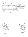
- the two coupling parts 10 and 12 are also coupled Condition shown. Unlike in Figures 3 and 4, here are the coupling parts 10 and 12, however, not arranged on a line, but tilted against each other. This means that the optical axes of the light-guiding elements 18, which each coincide with the axis of symmetry of the transparent core 24, stand at an angle to each other. Because of their spherical shape the end faces 26 and 26 'nevertheless lie against one another without gaps, so that the attenuation of the light as it passes through the end faces 26 and 26 ' keeps within limits. The optical fiber coupling can therefore be bent to a certain degree, without affecting their function. This is a huge advantage compared to the flat end faces usually used, which in such a Tilt would be lifted from each other, so that the light transmission would be strongly damped from one coupling part to the other.
- FIG. 5 shows the light guide coupling in its maximally bent position, in which the coupling parts are tilted against each other by 11 °. Another When tilted, daylight would enter the light tunnel and the optical one Falsify signal.
- the critical angle at which daylight enters the light tunnel would depend on the ratio of the wall thickness of the opaque Sleeves in the area of the end faces 26 and 26 'to the radius of curvature End faces 26, 26 '.
- the wall thickness is opaque sleeve 22 of the first coupling part in the region of the end face 26 less than that of the opaque sleeve 22 of the second coupling part 12, and thus decisive for the determination of the critical angle. It is approximately 1/5 of the radius of curvature of the spherical end faces 26 and 26 '.
- optical fiber coupling shown in Figures 1 to 5 includes a transmitter 38 and a receiver 40 that Features described so far, in particular the spherical design the end faces 26 and 26 'also for optical fiber couplings in the conventional Senses are intended in which no such active elements are provided are. In this case, light would go from an optical fiber into the light-guiding Element 18 of the first coupling part 10 fed through the end face 26 and the end face 26 'of the light-guiding element 18 of the second Coupling part 12 transmitted and in one with the light-guiding element 18th of the second coupling part connected optical fiber passed on.
- the Transmitting and receiving devices 38 and 40 are only advantageous Further development of the invention, which is described below.
- FIG. 9 shows a functional sketch of the transmission device 38.
- an input voltage V in present between the ground connection 42 and the signal connection 44 is scaled via a resistor 61 and is applied via a high pass consisting of a capacitor 62 and a resistor 64 to a light-emitting diode 66 which emits light corresponding to the applied voltage
- the relationship between the applied voltage V in and the radiation power S of the light-emitting diode 66 is shown schematically in a diagram in the right part of FIG. 9, the abscissa of which indicates the time and the ordinate of which indicates the input voltage V in and the radiation power S in undetermined units.
- FIG. 10 shows a functional sketch of the receiving device 40.
- the receiving device 40 contains a photodiode 68 which generates a voltage as a function of the intensity of the incident light. This is suitably amplified in a first circuit section with the aid of an operational amplifier 70, a resistor 72 and a capacitor 74 and inverted to an output voltage V out with the aid of a further operational amplifier 76.
- the relationship between the received radiation power S '(which corresponds to a damping factor corresponding to the radiation power emitted by the LED 66) and the output signal V out of the receiving device 40 is shown schematically in a diagram in the right part of FIG Ordinate shows the received radiation power S 'and the output voltage V out in indefinite units.
- the transmitting device 38 and the receiving device 40 are designed such that the output signal V out of the receiving device 40 corresponds to the input voltage V in despite possible attenuation of the transmitted optical signal. Thus, even if the optical signal transmitted between the coupling parts 10 and 12 is subjected to a certain attenuation, the effectively transmitted electrical signal V out is not attenuated compared to the original signal V in .
- the electrical input signal V in can be, for example, an electrical high-frequency signal that is conducted within two vehicle parts via a coaxial cable and is only converted into an optical signal with the aid of the transmitting device 38 to pass the optical fiber coupling.
- the further developed optical fiber coupling with the active elements 38 and 40 is also used when optical signals are already being transmitted in the vehicle parts by optical fibers. These are then first converted into an electrical signal in the first coupling part, which is then applied to the transmission device 38.
- the output signal V out of the receiving device 40 is then again converted into an optical signal in the second coupling part and fed into a further optical waveguide.
- FIG. 11 shows a section of a line coupling for use in combination with an automatic rail vehicle coupling in sectional view shown.
- An automatic clutch is used when the train parts must be coupled and uncoupled more frequently. Then the corresponding one Cable coupling designed so that its electrical and optical contacts also automatically coupled when the train parts are coupled become.
- the cable coupling includes two contact carriers 78 and 80, in which in addition a series of electrical contacts (not shown) also those described above Coupling parts 10 and 12 of the optical fiber coupling are used.
- the coupling parts 10 and 12 are on the end face with the thread 54 of the connecting bolt screwed into the contact carrier 78 or 80, whereby the thread 54 Is ground potential.
- the signal contact section 50 comes of the first coupling part 10 with a schematically illustrated first signal processing unit 82 and the signal connection section 50 of the second Coupling part 12 with a schematically illustrated second signal processing unit 84 electrically in contact.
- the first signal processing unit 82 via a coaxial cable 86 electrical signals and an optical fiber 88 optical signals supplied.
- the optical signals 88 are in a converter unit 90 converted into electrical signals and together with the electrical Signals from the electrical line 86 of a control unit 92 fed.
- the control unit 92 the two incoming electrical Signals processed into a multiplex signal that is sent to the signal connector 50 of the first coupling part is transmitted.
- the control unit 92 a microprocessor (not shown), which is a Industrial PC or a so-called Field Programmable Gate Array (FPGA) is.
- the control unit 92 also has a data input 94, via which you can access further data Signal processing information is supplied.
- the data line 94 signals that signals that have already been transmitted have arrived incomplete and have to be sent again.
- the conversion of the electrical multiplex signals into optical signals by the Transmitter 38 and its transmission from the first coupling part 10 the second coupling part 12 take place as described above. From the signal connection 50 of the second coupling part 12 arrive in the receiving device 40 generated electrical signals in a control unit 96 of the second signal processing unit 84. The Multiplex signals broken down into individual signals. The originally about the electrical Line 86 received signals are through an electrical line 98 forwarded. Those originally received via the optical fiber 88 Signals are converted into optical signals in a converter unit 100 and fed into an optical waveguide 102.
- Signals from the control unit can be transmitted via a further data line 104 96 are forwarded, for example error signals if signals are faulty were received.
- the control unit 96 also contains an industrial PC or an FPGA (not shown).
- the signal processing units 82 and 84 can also in the housing 14 of the Clutch boy parts can be accommodated. Furthermore, the signal processing units 82 and 84 each with a transmitting coupling part (similar to that first coupling part 10) and a receivable coupling part (similar the second coupling part 12). Then signals from both Sides of the clutch are transferred to the other side and the signal processing units 82 and 84 can be in both directions with each other communicate.
- the coupling parts 10 and 12 can, however, not only as shown in Fig. 11 in special contact carriers, but also directly in the coupling heads of one mechanical rail vehicle coupling, for example an automatic one Middle buffer coupling can be arranged (not shown).
- an automatic one Middle buffer coupling can be arranged (not shown).
Landscapes
- Engineering & Computer Science (AREA)
- Mechanical Engineering (AREA)
- Transportation (AREA)
- Optical Couplings Of Light Guides (AREA)
- Led Device Packages (AREA)
- Mechanical Coupling Of Light Guides (AREA)
- Mutual Connection Of Rods And Tubes (AREA)
- Pivots And Pivotal Connections (AREA)
- Light Receiving Elements (AREA)
- Photo Coupler, Interrupter, Optical-To-Optical Conversion Devices (AREA)
- Optical Integrated Circuits (AREA)
- Optical Communication System (AREA)
Abstract
Description
- Fig.1
- eine Schnittdarstellung eines ersten Kupplungsteiles einer Lichtleiterkupplung in Explosionsdarstellung (oben) und im zusammengesetzten Zustand (unten),
- Fig.2
- eine Schnittdarstellung eines zweiten Kupplungsteiles einer Lichtleiterkupplung in Explosionsdarstellung (oben) und im zusammengesetzten Zustand (unten),
- Fig.3
- eine Schnittdarstellung der Kupplungsteile von Figuren 1 und 2 im gekuppelten Zustand,
- Fig.4
- die gekuppelten Kupplungsteile von Figur 3, deren Abstand in Richtung der optischen Achse verkürzt ist,
- Fig.5
- die gekuppelten Kupplungsteile von Figur 3, deren optische Achsen gegeneinander verkippt sind,
- Fig.6
- einen Längsschnitt durch das Gehäuse des ersten Kupplungsteiles,
- Fig.7
- eine Querschnittsansicht des Gehäuses des ersten Kupplungsteiles,
- Fig.8
- eine Querschnittsansicht einer alternativen Ausführungsform des Gehäuses des ersten Kupplungsteiles,
- Fig.9
- eine Funktionsskizze einer Sendeeinrichtung des ersten Kupplungsteiles,
- Fig.10
- eine Funktionsskizze einer Empfangseinrichtung des zweiten Kupplungsteiles und
- Fig.11
- eine Schnittansicht eines Abschnitts einer Leitungskupplung für Schienenfahrzeuge mit zwei Kontaktträgern, in die jeweils ein Kupplungsteil der Lichtleiterkupplung eingesetzt ist.
- 10
- erstes Kupplungsteil
- 12
- zweites Kupplungsteil
- 14
- Gehäuse
- 16
- hülsenartiger Gehäuseabschnitt
- 18
- lichtleitendes Element
- 20
- Feder
- 22
- lichtundurchlässige Hülse
- 24
- transparenter Kern
- 26, 26'
- sphärische Stirnfläche
- 27
- Führungsnut
- 28
- Führungsbolzen
- 30
- innerer Innenraumabschnitt
- 32
- äußerer Innenraumabschnitt
- 34
- Absatz
- 36
- Metallring
- 38
- Sendeeinheit
- 40
- Empfangseinheit
- 42
- Masseanschluss
- 44
- Signalanschluss
- 46
- Anschlussbolzen
- 48
- Masseanschlussabschnitt .
- 50
- Signalanschlussabschnitt
- 52
- Isolierungsstück
- 54
- Außengewinde
- 56
- Innengewinde
- 57
- Bohrung
- 58
- Führungsbolzenaufnahme
- 60
- Führungsbolzenaufnahme
- 62
- Kondensator
- 64
- Widerstand
- 66
- LED
- 68
- Photodiode
- 70
- Operationsverstärker
- 72
- Widerstand
- 74
- Kondensator
- 76
- Operationsverstärker
- 78
- Kontaktträger
- 80
- Kontaktträger
- 82
- Signalverarbeitungseinheit
- 84
- Signalverarbeitungseinheit
- 86
- elektrische Signalleitung
- 88
- Lichtwellenleiter
- 90
- Signalwandler
- 92
- Steuerungseinheit
- 94
- Datenleitung
- 96
- Steuerungseinheit
- 98
- elektrische Signalleitung
- 100
- Signalwandler
- 102
- Lichtwellenleiter
- 104
- Datenleitung
Claims (12)
- Lichtleiterkupplung, insbesondere zum Übertragen von optischen Signalen zwischen miteinander gekuppelten Fahrzeugteilen, mit einem ersten und einem zweiten Kupplungsteil (10, 12), die miteinander kuppelbar sind und in denen jeweils ein lichtleitendes Element (18) gehalten ist, von denen mindestens eines derart elastisch vorgespannt ist, dass die lichtleitenden Elemente (18) mit ihren Stirnflächen (26, 26') aneinander gedrückt werden, wenn die Kupplungsteile (10, 12) miteinander gekuppelt sind, um eine Lichtübertragung von einem lichtleitenden Element (18) auf das andere zu gestatten, dadurch gekennzeichnet, dass die Stirnfläche (26) des einen lichtleitenden Elementes (18) sphärisch konkav und die Stirnfläche (26') des anderen lichtleitenden Elementes (18) mit gleichem Krümmungsradius sphärisch konvex ausgebildet ist.
- Lichtleiterkupplung nach Anspruch 1, dadurch gekennzeichnet, dass die lichtleitenden Elemente (18) jeweils aus einer lichtundurchlässigen Hülse (22) und einem darin aufgenommenen transparenten Kern (24) bestehen.
- Lichtleiterkupplung nach Anspruch 2, dadurch gekennzeichnet, dass die Wanddicke der Hülse (22) im Bereich der Stirnfläche (26, 26') mindestens 1/10, vorzugsweise mindestens 1/5 des Krümmungsradius der Stirnflächen (26, 26') beträgt.
- Lichtleiterkupplung nach einem der vorhergehenden Ansprüche, dadurch gekennzeichnet, dass das erste Kupplungsteil (10) eine Sendeeinrichtung (38) beinhaltet, die aus elektrischen Signalen optische Signale erzeugt und diese in das lichtleitende Element (18) des ersten Kupplungsteiles (10) einspeist.
- Lichtleiterkupplung nach Anspruch 4, dadurch gekennzeichnet, dass die Sendeeinrichtung (38) mindestens eine LED (66) zur Erzeugung der optischen Signale hat.
- Lichtleiterkupplung nach Anspruch 4 oder 5, dadurch gekennzeichnet, dass das erste Kupplungsteil (10) einen Mikroprozessor beinhaltet, der die elektrischen Signale für die Sendeeinrichtung (38) bereitstellt.
- Lichtleiterkupplung nach einem der vorhergehenden Ansprüche, dadurch gekennzeichnet, dass das zweite Kupplungsteil (12) eine Empfangseinrichtung (40) beinhaltet, die aus auf das lichtleitende Element (18) des zweiten Kupplungsteiles (12) übertragenen optischen Signalen elektrische Signale erzeugt.
- Lichtleiterkupplung nach Anspruch 7, dadurch gekennzeichnet, dass die Empfangseinrichtung (40) eine Photodiode (68) zum Detektieren der optischen Signale hat.
- Lichtleiterkupplung nach Anspruch 7 oder 8, dadurch gekennzeichnet, dass das zweite Kupplungsteil (12) einen Mikroprozessor beinhaltet, der das in der Empfangsvorrichtung (40) erzeugte elektrische Signal verarbeitet.
- Lichtleiterkupplung nach Anspruch 6 und 9, dadurch gekennzeichnet, dass der Mikroprozessor des ersten Kupplungsteiles programmiert ist, um mehrere individuelle Signale in elektrischen Multiplexsignalen zu vereinen, und der Mikroprozessor des zweiten Kupplungsteiles programmiert ist, um elektrische Multiplexsignale in individuelle Signale zu zerlegen.
- Lichtleiterkupplung nach einem der Ansprüche 4 bis 6 und/oder einem der Ansprüche 7 bis 9, dadurch gekennzeichnet, dass das erste und/oder zweite Kupplungsteil (10, 12) ein Gehäuse (14) hat, an dessen einem axialen Ende ein hülsenartiger Abschnitt (16) ausgebildet ist, in dem das lichtleitende Element (18) axial verschiebbar gelagert und in Richtung auf dieses eine axiale Ende elastisch vorgespannt ist, und an dessen anderem Ende ein Anschlussbolzen (46) ausgebildet ist, der zum Einsetzen in einen Kontaktträger (78, 80) bestimmt ist.
- Lichtleiterkupplung nach Anspruch 11, dadurch gekennzeichnet, dass der Anschlussbolzen (46) aus zwei gegeneinander isolierten Abschnitten (48, 50) besteht, von denen der eine mit dem Massepotential und der andere mit einer elektrischen Signalleitung verbunden ist, wenn der Anschlussbolzen (46) in den Kontaktträger (78, 80) eingesetzt ist.
Applications Claiming Priority (2)
| Application Number | Priority Date | Filing Date | Title |
|---|---|---|---|
| DE10310148A DE10310148B4 (de) | 2003-03-07 | 2003-03-07 | Lichtleiterkupplung |
| DE10310148 | 2003-03-07 |
Publications (3)
| Publication Number | Publication Date |
|---|---|
| EP1455207A1 true EP1455207A1 (de) | 2004-09-08 |
| EP1455207A8 EP1455207A8 (de) | 2004-12-08 |
| EP1455207B1 EP1455207B1 (de) | 2005-11-23 |
Family
ID=32797884
Family Applications (1)
| Application Number | Title | Priority Date | Filing Date |
|---|---|---|---|
| EP03010282A Expired - Lifetime EP1455207B1 (de) | 2003-03-07 | 2003-05-07 | Lichtleiterkupplung |
Country Status (8)
| Country | Link |
|---|---|
| US (1) | US6883973B2 (de) |
| EP (1) | EP1455207B1 (de) |
| JP (1) | JP4022515B2 (de) |
| CN (1) | CN1527079B (de) |
| AT (1) | ATE310968T1 (de) |
| AU (1) | AU2003255193B2 (de) |
| CA (1) | CA2447177C (de) |
| DE (2) | DE10310148B4 (de) |
Cited By (1)
| Publication number | Priority date | Publication date | Assignee | Title |
|---|---|---|---|---|
| WO2017182200A1 (de) * | 2016-04-19 | 2017-10-26 | Voith Patent Gmbh | Vorrichtung zur daten- und/oder signalübertragung |
Families Citing this family (15)
| Publication number | Priority date | Publication date | Assignee | Title |
|---|---|---|---|---|
| DE10310134B3 (de) * | 2003-03-07 | 2004-09-30 | Era-Contact Gmbh | Optische Signalkupplung |
| US7527437B2 (en) * | 2005-09-30 | 2009-05-05 | Rockwell Automation Technologies, Inc. | Sensor mounting structure with light pipe |
| KR101461249B1 (ko) * | 2007-02-15 | 2014-11-12 | 델러 커플러스 아베 | 철도 차량들의 연결을 위해 배치된 열차 커플러 내의 커넥터 및 연결 블록 |
| EP2469156A4 (de) * | 2010-07-16 | 2014-09-10 | Toshiba Lighting & Technology | Lampenvorrichtung und beleuchtungsvorrichtung |
| CN103837955B (zh) * | 2012-11-26 | 2016-08-31 | 福州高意通讯有限公司 | 一种光学器件的装配结构及方法 |
| DE102015105514A1 (de) * | 2015-04-10 | 2016-10-13 | Voith Patent Gmbh | Vorrichtung zum Übertragen von Daten und/oder Signalen |
| DE102015107230A1 (de) | 2015-05-08 | 2016-11-10 | Voith Patent Gmbh | Schnittstellenanordnung für eine Daten-, Signal- und/oder Sprachübertragung |
| CN106394595B (zh) * | 2015-07-31 | 2018-03-30 | 瑞安市建鑫机械制造有限公司 | 车厢铰连接器及其加工工艺 |
| EP3379222B1 (de) | 2017-03-22 | 2020-12-30 | Methode Electronics Malta Ltd. | Auf magnetoelastik basierte sensoranordnung |
| US11135882B2 (en) | 2018-02-27 | 2021-10-05 | Methode Electronics, Inc. | Towing systems and methods using magnetic field sensing |
| EP3758959B1 (de) | 2018-02-27 | 2025-11-05 | Methode Electronics, Inc. | Schleppsysteme und -verfahren mit verwendung von magnetfeldmessung |
| US11491832B2 (en) | 2018-02-27 | 2022-11-08 | Methode Electronics, Inc. | Towing systems and methods using magnetic field sensing |
| US11221262B2 (en) | 2018-02-27 | 2022-01-11 | Methode Electronics, Inc. | Towing systems and methods using magnetic field sensing |
| US11084342B2 (en) | 2018-02-27 | 2021-08-10 | Methode Electronics, Inc. | Towing systems and methods using magnetic field sensing |
| CN110426787B (zh) * | 2019-07-04 | 2020-12-22 | 苏州安捷讯光电科技股份有限公司 | 一种带衰减非接触式光纤回路器及其制作方法 |
Citations (5)
| Publication number | Priority date | Publication date | Assignee | Title |
|---|---|---|---|---|
| GB381354A (en) * | 1931-10-26 | 1932-10-06 | Macintosh Cable Company Ltd | An improved electrical joint, coupling or connection |
| US4284311A (en) * | 1978-12-20 | 1981-08-18 | Scharfenbergkupplung Gmbh | Mechanical central buffer coupling for rail vehicles |
| US4964690A (en) * | 1988-06-09 | 1990-10-23 | Erni Elektroapparate Gmbh | Pin-and-socket connector for light wave conductors |
| DE19807596A1 (de) * | 1997-02-22 | 1998-09-10 | Spinner Gmbh Elektrotech | LWL-Steckverbindung |
| US6481738B1 (en) * | 1998-06-15 | 2002-11-19 | Excalibur Vehicle Accessories (Proprietary) Limited | Connecting device |
Family Cites Families (8)
| Publication number | Priority date | Publication date | Assignee | Title |
|---|---|---|---|---|
| DE2922937C2 (de) | 1979-06-01 | 1981-07-02 | Fabeg Gmbh, 7518 Bretten | Kabelkupplung zum selbsttätigen Durchkuppeln elektrischer Heiz- und/oder Steuerstromleitungen sowie von Lichtleitern zur optischen Befehlsübertragung, insbesondere für Bahnfahrzeuge |
| US4699454A (en) * | 1984-03-29 | 1987-10-13 | American Telephone And Telegraph Company, At&T Bell Laboratories | Fiber optic connector |
| US4807955A (en) * | 1987-08-06 | 1989-02-28 | Amp Incorporated | Opto-electrical connecting means |
| SE465098B (sv) * | 1989-04-25 | 1991-07-22 | Ericsson Telefon Ab L M | Kontaktdon |
| IT1239223B (it) * | 1990-02-20 | 1993-09-28 | Pirelli Cavi Spa | Connettore ottico orientabile per collegamento di fibre ottiche a componenti ottici discreti e sensore impiegante uno o piu' connettori orientabili |
| CN1083242A (zh) * | 1992-08-15 | 1994-03-02 | 华中理工大学 | 公交车辆监控数据采集系统 |
| DE29701845U1 (de) * | 1997-02-04 | 1997-03-20 | Connex Elektrotechnische Stecksysteme GmbH, 49393 Lohne | Schnittstelle mit einem opto-elektrischen Wandler |
| DE10052020A1 (de) | 2000-10-20 | 2002-05-08 | Knorr Bremse Systeme | Steckverbindung |
-
2003
- 2003-03-07 DE DE10310148A patent/DE10310148B4/de not_active Expired - Fee Related
- 2003-05-07 EP EP03010282A patent/EP1455207B1/de not_active Expired - Lifetime
- 2003-05-07 AT AT03010282T patent/ATE310968T1/de not_active IP Right Cessation
- 2003-05-07 DE DE50301732T patent/DE50301732D1/de not_active Expired - Lifetime
- 2003-08-13 CN CN031278825A patent/CN1527079B/zh not_active Expired - Fee Related
- 2003-10-20 AU AU2003255193A patent/AU2003255193B2/en not_active Ceased
- 2003-10-27 US US10/694,371 patent/US6883973B2/en not_active Expired - Lifetime
- 2003-10-28 CA CA002447177A patent/CA2447177C/en not_active Expired - Fee Related
- 2003-12-19 JP JP2003423376A patent/JP4022515B2/ja not_active Expired - Fee Related
Patent Citations (5)
| Publication number | Priority date | Publication date | Assignee | Title |
|---|---|---|---|---|
| GB381354A (en) * | 1931-10-26 | 1932-10-06 | Macintosh Cable Company Ltd | An improved electrical joint, coupling or connection |
| US4284311A (en) * | 1978-12-20 | 1981-08-18 | Scharfenbergkupplung Gmbh | Mechanical central buffer coupling for rail vehicles |
| US4964690A (en) * | 1988-06-09 | 1990-10-23 | Erni Elektroapparate Gmbh | Pin-and-socket connector for light wave conductors |
| DE19807596A1 (de) * | 1997-02-22 | 1998-09-10 | Spinner Gmbh Elektrotech | LWL-Steckverbindung |
| US6481738B1 (en) * | 1998-06-15 | 2002-11-19 | Excalibur Vehicle Accessories (Proprietary) Limited | Connecting device |
Cited By (2)
| Publication number | Priority date | Publication date | Assignee | Title |
|---|---|---|---|---|
| WO2017182200A1 (de) * | 2016-04-19 | 2017-10-26 | Voith Patent Gmbh | Vorrichtung zur daten- und/oder signalübertragung |
| US10752268B2 (en) | 2016-04-19 | 2020-08-25 | Voith Patent Gmbh | Device for data and/or signal transmission |
Also Published As
| Publication number | Publication date |
|---|---|
| DE10310148A1 (de) | 2004-12-23 |
| CA2447177C (en) | 2007-08-07 |
| JP4022515B2 (ja) | 2007-12-19 |
| DE10310148B4 (de) | 2005-03-03 |
| CN1527079B (zh) | 2010-05-12 |
| AU2003255193A1 (en) | 2004-09-23 |
| CN1527079A (zh) | 2004-09-08 |
| EP1455207B1 (de) | 2005-11-23 |
| ATE310968T1 (de) | 2005-12-15 |
| CA2447177A1 (en) | 2004-09-07 |
| EP1455207A8 (de) | 2004-12-08 |
| US20040175076A1 (en) | 2004-09-09 |
| AU2003255193B2 (en) | 2008-09-25 |
| JP2004268904A (ja) | 2004-09-30 |
| US6883973B2 (en) | 2005-04-26 |
| DE50301732D1 (de) | 2005-12-29 |
| HK1068415A1 (zh) | 2005-04-29 |
Similar Documents
| Publication | Publication Date | Title |
|---|---|---|
| EP1455207B1 (de) | Lichtleiterkupplung | |
| DE10310134B3 (de) | Optische Signalkupplung | |
| DE2812284C2 (de) | Ausrichtvorrichtung für optische Einzelfaserleitungen | |
| DE102008048440B4 (de) | Mittelpufferkupplung für schienengebundene Fahrzeuge | |
| DE3587180T2 (de) | Faseroptischer Stecker. | |
| EP0395708B1 (de) | Verbindungsstück | |
| EP0313738B1 (de) | Verfahren zur bidirektionalen Uebertragung optischer Signale ueber Lichtwellenleiter | |
| EP3280629A1 (de) | Vorrichtung zum übertragen von daten und/oder signalen | |
| EP1187262A2 (de) | Isolierkörper für einen Steckverbinder zur Übertragung optischer und elektrischer Signale | |
| DE2741585B2 (de) | Einschubsteckverbindung fur Lichtwellenleiter | |
| EP0304639A2 (de) | Steckvorrichtung für die Übertragung von elektrischer Energie und von optischen Signalen | |
| WO2015117251A1 (de) | Am einsatzort konfektionierbarer optischer stecker | |
| DE4414862C2 (de) | Lichtwellenleiter-Steckverbinder mit Überwachungseinrichtung | |
| EP1869805B1 (de) | Elektrooptische kopplungseinrichtung | |
| WO2000016142A2 (de) | Mehrkanalige optische kopplungseinrichtung | |
| DE9319378U1 (de) | Kombinierte Sende- und Empfangsstation für die optische Nachrichtenübertragung | |
| DE3733018B4 (de) | Optokoppler | |
| EP0990914A2 (de) | Prüfeinrichtung für mit Lichtwellenleitern bestückte Stecker | |
| DE4141009A1 (de) | Abschlussvorrichtung fuer lichtwellenleiter | |
| DE202005005767U1 (de) | Elektrooptische Kopplungseinrichtung | |
| AT502359A2 (de) | Medizinisches laserbehandlungsgerät | |
| EP0092217A2 (de) | Lichtwellenleitersteckvorrichtung insbesondere für die Einschubtechnik | |
| HK1068415B (en) | Light conductor coupling | |
| DE10131374A1 (de) | Anordnung zur Positionierung einer optischen Faser | |
| DD255459A3 (de) | Anordnung zur wechselseitigen signaluebertragung ueber einen lichtwellenleiter |
Legal Events
| Date | Code | Title | Description |
|---|---|---|---|
| PUAI | Public reference made under article 153(3) epc to a published international application that has entered the european phase |
Free format text: ORIGINAL CODE: 0009012 |
|
| AK | Designated contracting states |
Kind code of ref document: A1 Designated state(s): AT BE BG CH CY CZ DE DK EE ES FI FR GB GR HU IE IT LI LU MC NL PT RO SE SI SK TR |
|
| AX | Request for extension of the european patent |
Extension state: AL LT LV MK |
|
| 17P | Request for examination filed |
Effective date: 20041203 |
|
| GRAP | Despatch of communication of intention to grant a patent |
Free format text: ORIGINAL CODE: EPIDOSNIGR1 |
|
| AKX | Designation fees paid |
Designated state(s): AT BE BG CH CY CZ DE DK EE ES FI FR GB GR HU IE IT LI LU MC NL PT RO SE SI SK TR |
|
| GRAS | Grant fee paid |
Free format text: ORIGINAL CODE: EPIDOSNIGR3 |
|
| GRAA | (expected) grant |
Free format text: ORIGINAL CODE: 0009210 |
|
| AK | Designated contracting states |
Kind code of ref document: B1 Designated state(s): AT BE BG CH CY CZ DE DK EE ES FI FR GB GR HU IE IT LI LU MC NL PT RO SE SI SK TR |
|
| PG25 | Lapsed in a contracting state [announced via postgrant information from national office to epo] |
Ref country code: IT Free format text: LAPSE BECAUSE OF FAILURE TO SUBMIT A TRANSLATION OF THE DESCRIPTION OR TO PAY THE FEE WITHIN THE PRESCRIBED TIME-LIMIT;WARNING: LAPSES OF ITALIAN PATENTS WITH EFFECTIVE DATE BEFORE 2007 MAY HAVE OCCURRED AT ANY TIME BEFORE 2007. THE CORRECT EFFECTIVE DATE MAY BE DIFFERENT FROM THE ONE RECORDED. Effective date: 20051123 Ref country code: IE Free format text: LAPSE BECAUSE OF FAILURE TO SUBMIT A TRANSLATION OF THE DESCRIPTION OR TO PAY THE FEE WITHIN THE PRESCRIBED TIME-LIMIT Effective date: 20051123 Ref country code: CZ Free format text: LAPSE BECAUSE OF FAILURE TO SUBMIT A TRANSLATION OF THE DESCRIPTION OR TO PAY THE FEE WITHIN THE PRESCRIBED TIME-LIMIT Effective date: 20051123 Ref country code: SI Free format text: LAPSE BECAUSE OF FAILURE TO SUBMIT A TRANSLATION OF THE DESCRIPTION OR TO PAY THE FEE WITHIN THE PRESCRIBED TIME-LIMIT Effective date: 20051123 Ref country code: FI Free format text: LAPSE BECAUSE OF FAILURE TO SUBMIT A TRANSLATION OF THE DESCRIPTION OR TO PAY THE FEE WITHIN THE PRESCRIBED TIME-LIMIT Effective date: 20051123 Ref country code: SK Free format text: LAPSE BECAUSE OF FAILURE TO SUBMIT A TRANSLATION OF THE DESCRIPTION OR TO PAY THE FEE WITHIN THE PRESCRIBED TIME-LIMIT Effective date: 20051123 Ref country code: NL Free format text: LAPSE BECAUSE OF FAILURE TO SUBMIT A TRANSLATION OF THE DESCRIPTION OR TO PAY THE FEE WITHIN THE PRESCRIBED TIME-LIMIT Effective date: 20051123 Ref country code: RO Free format text: LAPSE BECAUSE OF FAILURE TO SUBMIT A TRANSLATION OF THE DESCRIPTION OR TO PAY THE FEE WITHIN THE PRESCRIBED TIME-LIMIT Effective date: 20051123 |
|
| REG | Reference to a national code |
Ref country code: GB Ref legal event code: FG4D Free format text: NOT ENGLISH |
|
| REG | Reference to a national code |
Ref country code: CH Ref legal event code: EP |
|
| REF | Corresponds to: |
Ref document number: 50301732 Country of ref document: DE Date of ref document: 20051229 Kind code of ref document: P |
|
| REG | Reference to a national code |
Ref country code: IE Ref legal event code: FG4D Free format text: LANGUAGE OF EP DOCUMENT: GERMAN |
|
| GBT | Gb: translation of ep patent filed (gb section 77(6)(a)/1977) |
Effective date: 20060107 |
|
| REG | Reference to a national code |
Ref country code: SE Ref legal event code: TRGR |
|
| PG25 | Lapsed in a contracting state [announced via postgrant information from national office to epo] |
Ref country code: BG Free format text: LAPSE BECAUSE OF FAILURE TO SUBMIT A TRANSLATION OF THE DESCRIPTION OR TO PAY THE FEE WITHIN THE PRESCRIBED TIME-LIMIT Effective date: 20060223 Ref country code: GR Free format text: LAPSE BECAUSE OF FAILURE TO SUBMIT A TRANSLATION OF THE DESCRIPTION OR TO PAY THE FEE WITHIN THE PRESCRIBED TIME-LIMIT Effective date: 20060223 Ref country code: DK Free format text: LAPSE BECAUSE OF FAILURE TO SUBMIT A TRANSLATION OF THE DESCRIPTION OR TO PAY THE FEE WITHIN THE PRESCRIBED TIME-LIMIT Effective date: 20060223 |
|
| PG25 | Lapsed in a contracting state [announced via postgrant information from national office to epo] |
Ref country code: ES Free format text: LAPSE BECAUSE OF FAILURE TO SUBMIT A TRANSLATION OF THE DESCRIPTION OR TO PAY THE FEE WITHIN THE PRESCRIBED TIME-LIMIT Effective date: 20060306 |
|
| PG25 | Lapsed in a contracting state [announced via postgrant information from national office to epo] |
Ref country code: PT Free format text: LAPSE BECAUSE OF FAILURE TO SUBMIT A TRANSLATION OF THE DESCRIPTION OR TO PAY THE FEE WITHIN THE PRESCRIBED TIME-LIMIT Effective date: 20060424 |
|
| NLV1 | Nl: lapsed or annulled due to failure to fulfill the requirements of art. 29p and 29m of the patents act | ||
| PG25 | Lapsed in a contracting state [announced via postgrant information from national office to epo] |
Ref country code: AT Free format text: LAPSE BECAUSE OF NON-PAYMENT OF DUE FEES Effective date: 20060507 |
|
| PG25 | Lapsed in a contracting state [announced via postgrant information from national office to epo] |
Ref country code: HU Free format text: LAPSE BECAUSE OF FAILURE TO SUBMIT A TRANSLATION OF THE DESCRIPTION OR TO PAY THE FEE WITHIN THE PRESCRIBED TIME-LIMIT Effective date: 20060524 |
|
| PG25 | Lapsed in a contracting state [announced via postgrant information from national office to epo] |
Ref country code: MC Free format text: LAPSE BECAUSE OF NON-PAYMENT OF DUE FEES Effective date: 20060531 Ref country code: BE Free format text: LAPSE BECAUSE OF NON-PAYMENT OF DUE FEES Effective date: 20060531 |
|
| REG | Reference to a national code |
Ref country code: IE Ref legal event code: FD4D |
|
| ET | Fr: translation filed | ||
| PLBE | No opposition filed within time limit |
Free format text: ORIGINAL CODE: 0009261 |
|
| STAA | Information on the status of an ep patent application or granted ep patent |
Free format text: STATUS: NO OPPOSITION FILED WITHIN TIME LIMIT |
|
| 26N | No opposition filed |
Effective date: 20060824 |
|
| BERE | Be: lapsed |
Owner name: ERA-CONTACT G.M.B.H. Effective date: 20060531 |
|
| REG | Reference to a national code |
Ref country code: CH Ref legal event code: PL |
|
| PG25 | Lapsed in a contracting state [announced via postgrant information from national office to epo] |
Ref country code: LI Free format text: LAPSE BECAUSE OF NON-PAYMENT OF DUE FEES Effective date: 20070531 Ref country code: CH Free format text: LAPSE BECAUSE OF NON-PAYMENT OF DUE FEES Effective date: 20070531 |
|
| PG25 | Lapsed in a contracting state [announced via postgrant information from national office to epo] |
Ref country code: EE Free format text: LAPSE BECAUSE OF FAILURE TO SUBMIT A TRANSLATION OF THE DESCRIPTION OR TO PAY THE FEE WITHIN THE PRESCRIBED TIME-LIMIT Effective date: 20051123 |
|
| PG25 | Lapsed in a contracting state [announced via postgrant information from national office to epo] |
Ref country code: TR Free format text: LAPSE BECAUSE OF FAILURE TO SUBMIT A TRANSLATION OF THE DESCRIPTION OR TO PAY THE FEE WITHIN THE PRESCRIBED TIME-LIMIT Effective date: 20051123 Ref country code: LU Free format text: LAPSE BECAUSE OF NON-PAYMENT OF DUE FEES Effective date: 20060507 |
|
| PG25 | Lapsed in a contracting state [announced via postgrant information from national office to epo] |
Ref country code: CY Free format text: LAPSE BECAUSE OF FAILURE TO SUBMIT A TRANSLATION OF THE DESCRIPTION OR TO PAY THE FEE WITHIN THE PRESCRIBED TIME-LIMIT Effective date: 20051123 |
|
| PGFP | Annual fee paid to national office [announced via postgrant information from national office to epo] |
Ref country code: GB Payment date: 20130522 Year of fee payment: 11 Ref country code: DE Payment date: 20130624 Year of fee payment: 11 Ref country code: SE Payment date: 20130521 Year of fee payment: 11 |
|
| PGFP | Annual fee paid to national office [announced via postgrant information from national office to epo] |
Ref country code: FR Payment date: 20130604 Year of fee payment: 11 |
|
| REG | Reference to a national code |
Ref country code: DE Ref legal event code: R119 Ref document number: 50301732 Country of ref document: DE |
|
| GBPC | Gb: european patent ceased through non-payment of renewal fee |
Effective date: 20140507 |
|
| PG25 | Lapsed in a contracting state [announced via postgrant information from national office to epo] |
Ref country code: SE Free format text: LAPSE BECAUSE OF NON-PAYMENT OF DUE FEES Effective date: 20140508 |
|
| REG | Reference to a national code |
Ref country code: SE Ref legal event code: EUG |
|
| REG | Reference to a national code |
Ref country code: DE Ref legal event code: R119 Ref document number: 50301732 Country of ref document: DE Effective date: 20141202 |
|
| REG | Reference to a national code |
Ref country code: FR Ref legal event code: ST Effective date: 20150130 |
|
| PG25 | Lapsed in a contracting state [announced via postgrant information from national office to epo] |
Ref country code: DE Free format text: LAPSE BECAUSE OF NON-PAYMENT OF DUE FEES Effective date: 20141202 |
|
| PG25 | Lapsed in a contracting state [announced via postgrant information from national office to epo] |
Ref country code: GB Free format text: LAPSE BECAUSE OF NON-PAYMENT OF DUE FEES Effective date: 20140507 Ref country code: FR Free format text: LAPSE BECAUSE OF NON-PAYMENT OF DUE FEES Effective date: 20140602 |