EP1455054A1 - Abschaltsystem zur Vermeidung eines Überdrehzahlzustandes bei einem Wellenbruch - Google Patents
Abschaltsystem zur Vermeidung eines Überdrehzahlzustandes bei einem Wellenbruch Download PDFInfo
- Publication number
- EP1455054A1 EP1455054A1 EP04090048A EP04090048A EP1455054A1 EP 1455054 A1 EP1455054 A1 EP 1455054A1 EP 04090048 A EP04090048 A EP 04090048A EP 04090048 A EP04090048 A EP 04090048A EP 1455054 A1 EP1455054 A1 EP 1455054A1
- Authority
- EP
- European Patent Office
- Prior art keywords
- shaft
- switch
- electrical
- sensors
- axial
- Prior art date
- Legal status (The legal status is an assumption and is not a legal conclusion. Google has not performed a legal analysis and makes no representation as to the accuracy of the status listed.)
- Granted
Links
- 239000000446 fuel Substances 0.000 claims description 27
- 230000001939 inductive effect Effects 0.000 claims description 11
- 230000006835 compression Effects 0.000 claims description 9
- 238000007906 compression Methods 0.000 claims description 9
- 230000003287 optical effect Effects 0.000 claims description 9
- 239000004020 conductor Substances 0.000 claims description 7
- 210000000056 organ Anatomy 0.000 claims description 5
- 230000009471 action Effects 0.000 claims description 4
- 239000012212 insulator Substances 0.000 claims description 4
- 230000002093 peripheral effect Effects 0.000 claims description 4
- 238000006073 displacement reaction Methods 0.000 claims description 2
- 238000001514 detection method Methods 0.000 description 4
- 238000000034 method Methods 0.000 description 3
- 230000008569 process Effects 0.000 description 3
- 230000008901 benefit Effects 0.000 description 2
- 230000008859 change Effects 0.000 description 2
- 238000011161 development Methods 0.000 description 2
- 230000018109 developmental process Effects 0.000 description 2
- 210000003746 feather Anatomy 0.000 description 2
- 239000000463 material Substances 0.000 description 2
- 239000002184 metal Substances 0.000 description 2
- 229920000049 Carbon (fiber) Polymers 0.000 description 1
- 230000001133 acceleration Effects 0.000 description 1
- 239000013543 active substance Substances 0.000 description 1
- 239000004917 carbon fiber Substances 0.000 description 1
- 230000000052 comparative effect Effects 0.000 description 1
- 239000002131 composite material Substances 0.000 description 1
- 230000007274 generation of a signal involved in cell-cell signaling Effects 0.000 description 1
- 230000000977 initiatory effect Effects 0.000 description 1
- 239000003562 lightweight material Substances 0.000 description 1
- 230000007246 mechanism Effects 0.000 description 1
- VNWKTOKETHGBQD-UHFFFAOYSA-N methane Chemical compound C VNWKTOKETHGBQD-UHFFFAOYSA-N 0.000 description 1
- 239000012811 non-conductive material Substances 0.000 description 1
- 239000004033 plastic Substances 0.000 description 1
- 230000004044 response Effects 0.000 description 1
- 238000007789 sealing Methods 0.000 description 1
- 230000015607 signal release Effects 0.000 description 1
- 230000004584 weight gain Effects 0.000 description 1
- 235000019786 weight gain Nutrition 0.000 description 1
Images



Classifications
-
- F—MECHANICAL ENGINEERING; LIGHTING; HEATING; WEAPONS; BLASTING
- F02—COMBUSTION ENGINES; HOT-GAS OR COMBUSTION-PRODUCT ENGINE PLANTS
- F02C—GAS-TURBINE PLANTS; AIR INTAKES FOR JET-PROPULSION PLANTS; CONTROLLING FUEL SUPPLY IN AIR-BREATHING JET-PROPULSION PLANTS
- F02C9/00—Controlling gas-turbine plants; Controlling fuel supply in air- breathing jet-propulsion plants
- F02C9/26—Control of fuel supply
- F02C9/46—Emergency fuel control
-
- F—MECHANICAL ENGINEERING; LIGHTING; HEATING; WEAPONS; BLASTING
- F01—MACHINES OR ENGINES IN GENERAL; ENGINE PLANTS IN GENERAL; STEAM ENGINES
- F01D—NON-POSITIVE DISPLACEMENT MACHINES OR ENGINES, e.g. STEAM TURBINES
- F01D21/00—Shutting-down of machines or engines, e.g. in emergency; Regulating, controlling, or safety means not otherwise provided for
- F01D21/003—Arrangements for testing or measuring
-
- F—MECHANICAL ENGINEERING; LIGHTING; HEATING; WEAPONS; BLASTING
- F01—MACHINES OR ENGINES IN GENERAL; ENGINE PLANTS IN GENERAL; STEAM ENGINES
- F01D—NON-POSITIVE DISPLACEMENT MACHINES OR ENGINES, e.g. STEAM TURBINES
- F01D21/00—Shutting-down of machines or engines, e.g. in emergency; Regulating, controlling, or safety means not otherwise provided for
- F01D21/04—Shutting-down of machines or engines, e.g. in emergency; Regulating, controlling, or safety means not otherwise provided for responsive to undesired position of rotor relative to stator or to breaking-off of a part of the rotor, e.g. indicating such position
- F01D21/045—Shutting-down of machines or engines, e.g. in emergency; Regulating, controlling, or safety means not otherwise provided for responsive to undesired position of rotor relative to stator or to breaking-off of a part of the rotor, e.g. indicating such position special arrangements in stators or in rotors dealing with breaking-off of part of rotor
-
- F—MECHANICAL ENGINEERING; LIGHTING; HEATING; WEAPONS; BLASTING
- F01—MACHINES OR ENGINES IN GENERAL; ENGINE PLANTS IN GENERAL; STEAM ENGINES
- F01D—NON-POSITIVE DISPLACEMENT MACHINES OR ENGINES, e.g. STEAM TURBINES
- F01D21/00—Shutting-down of machines or engines, e.g. in emergency; Regulating, controlling, or safety means not otherwise provided for
- F01D21/04—Shutting-down of machines or engines, e.g. in emergency; Regulating, controlling, or safety means not otherwise provided for responsive to undesired position of rotor relative to stator or to breaking-off of a part of the rotor, e.g. indicating such position
- F01D21/06—Shutting-down
-
- F—MECHANICAL ENGINEERING; LIGHTING; HEATING; WEAPONS; BLASTING
- F05—INDEXING SCHEMES RELATING TO ENGINES OR PUMPS IN VARIOUS SUBCLASSES OF CLASSES F01-F04
- F05D—INDEXING SCHEME FOR ASPECTS RELATING TO NON-POSITIVE-DISPLACEMENT MACHINES OR ENGINES, GAS-TURBINES OR JET-PROPULSION PLANTS
- F05D2270/00—Control
- F05D2270/01—Purpose of the control system
- F05D2270/02—Purpose of the control system to control rotational speed (n)
- F05D2270/021—Purpose of the control system to control rotational speed (n) to prevent overspeed
-
- Y—GENERAL TAGGING OF NEW TECHNOLOGICAL DEVELOPMENTS; GENERAL TAGGING OF CROSS-SECTIONAL TECHNOLOGIES SPANNING OVER SEVERAL SECTIONS OF THE IPC; TECHNICAL SUBJECTS COVERED BY FORMER USPC CROSS-REFERENCE ART COLLECTIONS [XRACs] AND DIGESTS
- Y02—TECHNOLOGIES OR APPLICATIONS FOR MITIGATION OR ADAPTATION AGAINST CLIMATE CHANGE
- Y02T—CLIMATE CHANGE MITIGATION TECHNOLOGIES RELATED TO TRANSPORTATION
- Y02T50/00—Aeronautics or air transport
- Y02T50/60—Efficient propulsion technologies, e.g. for aircraft
Definitions
- the invention relates to a shutdown system for avoidance an overspeed condition in the event of a shaft break, in particular to cut off the fuel supply for a Aircraft engine in the event of a break in the low-pressure turbine shaft, where the wave in question is based on its energy consuming side with a coaxially arranged reference shaft connected is.
- mechanical devices are also included one coaxially assigned to the turbine shaft, at the front, Energy consuming end attached reference shaft described. In the event of a wave break, it will conditional rotation of the turbine shaft relative to the reference shaft for mechanical action on the fuel shut-off valve used.
- a known mechanical Device of this type for limiting overspeed conditions in the event of a rupture of the low pressure turbine and the Fan of an aircraft engine connecting low-pressure turbine shaft are each at the rear end of the two waves Recesses formed.
- the on The wire rope pulling force is applied to a fuel shut-off valve transferred to close this and so the overspeed condition due to the interrupted fuel supply to limit.
- the known mechanical devices using a reference wave disadvantageous than it was only after a comparative large angle of rotation between turbine and reference shaft speak to.
- the purely mechanical training of the Switch-off system and in particular the cable connection from the turbine shaft to the fuel shut-off valve constructive complex and prone to wear.
- the invention is therefore based on the object, the known mechanical shutdown systems using a reference wave so that a break in the shortest possible time Time recognized and a resulting overspeed condition is prevented or quickly limited.
- the signal triggering element one axially in a housing part of the reference shaft movable, formed from piston rod and piston plate Piston in operative connection with at least one compression spring stands.
- the housing is in one of the main shaft outgoing guide sleeve from which the the driver pins on the piston plate Strive radially inwards.
- the mechanical-electronic training based on this The shutdown system is structurally simple and reliable educated.
- its main advantage is that a wave break in the shortest possible time, if necessary can already be detected in the opening phase and then immediately an electrical signal to the electronically controlled Interruption of further energy supply generated can become a dangerous overspeed condition is prevented or at least limited.
- Compared to the known Security systems can be significantly reduced Signal tripping times and thus switch-off times for the fuel supply, that in the present case around 1 to 3 milliseconds lie, can be achieved, so that not only the Risk of damage and the extent of damage but also the dimensioning required for safety reasons the engine rotors are reduced and thus weight is saved can be.
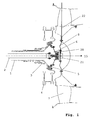
- Fig. 1 shows a partial view of a gas turbine engine in the area of the low-pressure turbine rotor 4.
- a reference shaft coaxial to the low-pressure turbine shaft 1 2 arranged in the front part (energy consuming Part) of the low-pressure turbine shaft 1 (not shown) is positively connected to this.
- a bearing bracket 3 At the back End of the low-pressure turbine shaft 1 are a bearing bracket 3 and the low pressure turbine rotor 4 attached.
- One on one Mounting flange 5 of the low pressure turbine rotor 4 attached Guide sleeve 6 takes the mechanical part of the shutdown system on, which is firmly connected to the reference shaft 2 is.
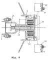
- the mechanical part of the shutdown system includes, as in particular 2 can be seen, one on one side the reference shaft 2 attached and on the other side in the guide sleeve connected to the low-pressure turbine shaft 1 6 guided housing 9 with a piston guide 10 and receptacles 11 for a prestressed compression spring 12 as a force exercising organ in the case of a Shaft failure.
- a piston guide 10 In the piston guide 10 is a piston rod 13 axially and rotatably guided, on the opposite End faces on the front in the flow direction 15 Side one acted upon by the spring force of the compression springs 12 Piston plate 14 (signal triggering element) and on the in Flow direction 15 rear side an the axial movement the piston plate 14 limiting in the flow direction Stop screw 16 are provided.
- the piston rod 13 and the piston plate 14 can be made of metal, plastic or Composite material, for example carbon fiber material or from a combination of lightweight materials and metal.
- On the guide sleeve 6 are in the axial direction extending driver 19 formed in a particular Angle of rotation of the cylindrical drive pins 17 are spaced.
- the electronic control and the power supply 25 to the fuel cut valve 23 connected inductive sensors 21 for inductive detection of a wave break and the following the fuel supply is interrupted.
- the piston plate 14 is now also rotated in the direction of arrow 26 and thereby axial bracket released by the locking hook 18.
- the piston plate 14 now freely movable in the axial direction is by the compression springs 12 in the direction of inductive Sensors 21 accelerated. Because of the change in distance between the piston plate 14 and the inductive sensors 21 electrical signals are generated in these which lead to the electronic control 24, which is via the fuel shut-off valve 23 interrupts the fuel supply become.
- the mechanical part and the one generating an electrical signal Part of the shutdown system are not on the present embodiment limited. So the cylindrical Driving pins 17, the locking hooks 18 and the drivers 19 and the compression springs 12 and the sensors 21 be arranged multiple times. Similarly, the compression spring 12 can also be accommodated centrally in the housing 9. Instead of the compression springs 12, others can also be on the piston plate 14 active agents, for example gas pressure, used become.
- an optical transmitter 27 instead of the inductive sensors and an optical receiver 28 attached to the holding plate 8, that if the optical connection is interrupted between the transmitter 27 and the receiver 28 through the released in the event of a wave break and moved backwards Piston plate 14 the required electrical signal is generated for the electronic control 24.
- Pairs of optical transmitters and receivers can be provided.
- FIG. 7 can with the mechanical shutdown mechanism unchanged the generation of the electrical signal for the electronic Controller 24 also with an electrical switching device respectively.
- the holding plate 8 a switch housing 29 integrated, in which a switching cylinder 30 is axially movable.
- the one with the piston plate 14 opposite flattened tip 31 as well trained with guide pins 38 for twist-proof guidance Shift cylinder 30 has a front circumference and a rear retaining groove 32 and 33.
- In the switch housing 29 there is a radial bore 34 in the one Locking device consisting of one under the action a spring 35 locking ball 36 is arranged.
- the spring 35 is held by a screw 37.
Landscapes
- Engineering & Computer Science (AREA)
- Mechanical Engineering (AREA)
- General Engineering & Computer Science (AREA)
- Chemical & Material Sciences (AREA)
- Combustion & Propulsion (AREA)
- Control Of Turbines (AREA)
Abstract
Description
- 1
- Welle, Niederdruckturbinenwelle
- 2
- Referenzwelle
- 3
- Lagerträger
- 4
- Niederdruckturbinenrotor, Energie erzeugende Seite v. 1
- 5
- Befestigungsflansch
- 6
- Führungshülse v. 1
- 7
- Turbinenaustrittsgehäuse
- 8
- Halteplatte
- 9
- Gehäuse
- 10
- Kolbenführung
- 11
- Aufnahmebuchse
- 12
- Druckfeder, Kraft ausübendes Organ
- 13
- Kolbenstange
- 14
- Kolbenplatte, Signalauslöseorgan
- 15
- Strömungsrichtung
- 16
- Anschlagschraube, Anschlag
- 17
- Mitnehmerstifte v. 14
- 18
- Sperrhaken v. 9
- 19
- Mitnehmer v. 6
- 20
- Sensorplatte
- 21
- Sensor, induktiver Sensor
- 22
- Verbindungskabel
- 23
- Kraftstoff-Absperrventil
- 24
- Elektronische Steuerung
- 25
- Stromversorgung
- 26
- Drehrichtung v. 6, 14
- 27
- Optischer Sender
- 28
- Optischer Empfänger
- 29
- Schaltergehäuse
- 30
- Schaltzylinder
- 31
- Abgeflachte Spitze v. 30
- 32
- Vordere Haltenut v. 30
- 33
- Hintere Haltenut v. 30
- 34
- Radiale Bohrung
- 35
- Feder
- 36
- Arretierkugel
- 37
- Schraube
- 38
- Führungsstifte v. 30
- 39
- Isolator
- 40
- Elektrischer Leiter v. 30
- 41
- Schalter
- 42a
- vorderer Kontaktstift v. 41
- 42b
- hinterer Kontaktstift v. 41
- 43
- Schraube
- 44
- Feder
- 45
- Dichtring
Claims (11)
- Abschaltsystem zur Vermeidung eines Überdrehzahlzustandes bei einem Wellenbruch, insbesondere zur Unterbrechung der Kraftstoffzufuhr für ein Flugzeugtriebwerk bei einem Bruch der Niederdruckturbinenwelle, wobei die betreffende Welle auf deren Energie verbrauchender Seite mit einer koaxial angeordneten Referenzwelle verbunden ist, dadurch gekennzeichnet, dass der Referenzwelle (2) auf der Energie erzeugenden Seite der Welle (1) ein an dieser axial und drehbar geführtes Signalauslöseorgan (13, 14) zugeordnet ist, das unter der Wirkung mindestens eines eine axiale Kraft ausübenden Organs (12) steht und über am Umfang des Signalauslöseorgans (13, 14) radial vorstehende Mitnehmerstifte (17) sowie Sperrhaken (18) in einer lösbaren Verriegelungsposition gehalten ist, wobei den Mitnehmerstiften (17) jeweils mit der Welle (1) verbundene Mitnehmer (19) in Umfangsrichtung seitlich gegenüberstehen, um im Falle eines Wellenbruchs und dem damit verbundenen Verdrehen der Welle (1) gegenüber der Referenzwelle (2) das Signalauslöseorgan (13, 14) aus der Verriegelungsposition zu lösen und dessen axiale Bewegung in Richtung mindestens eines dem Signalauslöseorgan (13, 14) axial gegenüberliegenden Sensors (21) oder elektrischen Schaltorgans (29, 30) zur Erzeugung eines elektrischen Signals für eine elektronische Steuerung (24) zur Unterbrechung der Energiezufuhr und Begrenzung eines Überdrehzahlzustandes freizugeben.
- Abschaltsystem nach Anspruch 1, dadurch gekennzeichnet, dass das Signalauslöseorgan eine an einer Kolbenstange (13) angebrachte Kolbenplatte (14) mit den an deren Umfangsfläche vorgesehenen Mitnehmerstiften (17) umfasst, und die Kolbenstange (13), die ein Anschlagelement (16) zur Begrenzung ihres Axialweges aufweist, in einem axial an die Referenzwelle (2) angeschlossenen Gehäuse (9) geführt ist, das in einer von der Welle (1) gebildeten Führungshülse (6) mit am Innenumfang angeordneten Mitnehmern (19) gelagert ist und Aufnahmebuchsen (11) für die eine axiale Kraftwirkung ausübenden Organe (12) sowie weiterhin die an den Mitnehmerstiften (17) angreifenden Sperrhaken (18) aufweist.
- Abschaltsystem nach Anspruch 2, dadurch gekennzeichnet, dass die eine axiale Kraftwirkung ausübenden Organe Druckfedern (12) oder Gasdruckorgane sind.
- Abschaltsystem nach Anspruch 2, dadurch gekennzeichnet, dass das Anschlagelement eine Anschlagschraube (16) ist.
- Abschaltvorrichtung nach Anspruch 1, dadurch gekennzeichnet, dass als Sensoren (21) induktive, kapazitive oder Ultraschallsensoren vorgesehen sind.
- Abschaltsystem nach Anspruch 5, dadurch gekennzeichnet, dass die Sensoren (21) an einer Sensorplatte (20) angebracht sind, die an einer mit dem Turbinengehäuse (7) verbundenen Halteplatte (8) montiert ist.
- Abschaltsystem nach Anspruch 5, dadurch gekennzeichnet, dass die Axialbewegung der Kolbenplatte (14) im Abstand vor den Sensoren (21) endet.
- Abschaltvorrichtung nach Anspruch 1, dadurch gekennzeichnet, dass als Sensoren optische Sensoren in Form eines optischen Senders und Empfängers (27, 28) vorgesehen sind, die im Abstand einander gegenüberliegend an der Halteplatte (8) des Turbinengehäuses (7) angebracht sind, wobei der axiale Weg der Kolbenplatte (14) so eingestellt ist, dass die Kolbenplatte (14) bei deren durch Wellenbruch freigegebener Bewegung den vom Sender (27) erzeugten Lichtstrahl unterbricht.
- Abschaltsystem nach Anspruch 1, dadurch gekennzeichnet, dass das elektrische Schaltorgan ein an der Halteplatte (8) montiertes Schaltgehäuse (29) mit Schalter (41) und einen darin in begrenztem Umfang axial beweglichen Schaltzylinder (30) umfasst, der bei axialer, infolge Wellenbruch initiierter Verschiebung durch das freigegebene Signalauslöseorgan (14) einen Stromkreis schließt und das elektrische Signal für die elektronische Steuerung (24) zur Unterbrechung der Energiezufuhr erzeugt.
- Abschaltsystem nach Anspruch 9, dadurch gekennzeichnet, dass in dem Schaltergehäuse (29) eine auf die Umfangsfläche des Schaltzylinders (30) wirkende federbelastete Arretierkugel (36) angeordnet ist, die den Schaltzylinder (30) über eine vordere und hintere Haltenut (32, 33) in dem jeweiligen Schaltzustand fixiert, wobei in den Schaltzylinder (30) ein Isolator (39) und ein mit dessen Umfangsfläche bündig abschließender elektrischer Leiter (40) eingelassen sind und in den Schalter (41) zwei in axialer Richtung hintereinander liegende, auf den Schaltzylinder (30) wirkende federbelastete Kontaktstifte (42a, 42b) eingebunden sind, die in der eingeschobenen Schaltstellung des Schaltzylinders (30) zur Erzeugung eines elektrischen Signals über den elektrischen Leiter (40) miteinander verbunden sind.
- Abschaltsystem nach Anspruch 1, dadurch gekennzeichnet, dass die Sensoren (21; 27, 28) und das elektrische Schaltorgan (29, 30) über ein elektrisches Verbindungskabel (22) mit der elektronischen Steuerung verbunden sind, die über eine Stromversorgung (25) an ein Kraftstoff-Absperrventil (23) zur Unterbrechung der Kraftstoffzufuhr angeschlossen ist.
Applications Claiming Priority (2)
| Application Number | Priority Date | Filing Date | Title |
|---|---|---|---|
| DE10309910 | 2003-03-07 | ||
| DE10309910A DE10309910A1 (de) | 2003-03-07 | 2003-03-07 | Abschaltsystem zur Vermeidung eines Überdrehzahlzustandes bei einem Wellenbruch |
Publications (2)
| Publication Number | Publication Date |
|---|---|
| EP1455054A1 true EP1455054A1 (de) | 2004-09-08 |
| EP1455054B1 EP1455054B1 (de) | 2006-03-22 |
Family
ID=32797849
Family Applications (1)
| Application Number | Title | Priority Date | Filing Date |
|---|---|---|---|
| EP04090048A Expired - Lifetime EP1455054B1 (de) | 2003-03-07 | 2004-02-13 | Abschaltsystem zur Vermeidung eines Überdrehzahlzustandes bei einem Wellenbruch |
Country Status (3)
| Country | Link |
|---|---|
| US (1) | US7100354B2 (de) |
| EP (1) | EP1455054B1 (de) |
| DE (2) | DE10309910A1 (de) |
Cited By (3)
| Publication number | Priority date | Publication date | Assignee | Title |
|---|---|---|---|---|
| WO2007036014A1 (en) * | 2005-09-27 | 2007-04-05 | Pratt & Whitney Canada Corp. | Emergency fuel shutoff system and method |
| EP1916391A1 (de) * | 2006-10-25 | 2008-04-30 | Snecma | Methode und Vorrichtung zur Geschwindigkeitsreduzierung im Falle eines Turbinenwellenbruchs in einem Gasturbinenmotor |
| US11504813B2 (en) | 2020-05-18 | 2022-11-22 | Rolls-Royce Plc | Methods for health monitoring of ceramic matrix composite components in gas turbine engines |
Families Citing this family (25)
| Publication number | Priority date | Publication date | Assignee | Title |
|---|---|---|---|---|
| DE102004033266A1 (de) * | 2004-07-09 | 2006-02-02 | Dr. Johannes Heidenhain Gmbh | Positionsmesseinrichtung und Verfahren zur Positionsmessung |
| DE102004047892A1 (de) * | 2004-10-01 | 2006-04-06 | Mtu Aero Engines Gmbh | Gasturbine und Verfahren zum Abschalten einer Gasturbine bei Identifikation eines Wellenbruchs |
| US7716971B2 (en) * | 2006-10-20 | 2010-05-18 | General Electric Company | Method and system for testing an overspeed protection system during a turbomachine shutdown sequence |
| US7677089B2 (en) * | 2006-10-30 | 2010-03-16 | General Electric Company | Method and system for testing the overspeed protection system of a turbomachine |
| US8104289B2 (en) * | 2007-10-09 | 2012-01-31 | United Technologies Corp. | Systems and methods involving multiple torque paths for gas turbine engines |
| FR2923540B1 (fr) * | 2007-11-13 | 2010-01-29 | Snecma | Dispositif de detection de rupture d'un arbre de turbomachine |
| DE102009054408B4 (de) | 2009-11-24 | 2018-06-07 | Rolls-Royce Deutschland Ltd & Co Kg | Gasturbine mit elektromechanischem Wellenbruch-Erkennungssystem |
| US9169742B2 (en) * | 2010-02-26 | 2015-10-27 | Pratt & Whitney Canada Corp. | Electronic shaft shear detection conditioning circuit |
| US20120171037A1 (en) * | 2011-01-03 | 2012-07-05 | Prathap Raj R | Probe assembly for use in turbine engines and method of assembling same |
| CN201958667U (zh) * | 2011-01-30 | 2011-09-07 | 漳州灿坤实业有限公司 | 一种烤面包机 |
| FR2987085B1 (fr) * | 2012-02-20 | 2014-03-21 | Snecma | Procede de securisation du fonctionnement d'une turbomachine |
| WO2014049257A1 (fr) * | 2012-09-28 | 2014-04-03 | Snecma | Bague d'interface hydraulique et electrique pour une turbomachine |
| US10167784B2 (en) | 2012-10-26 | 2019-01-01 | Pratt & Whitney Canada Corp. | System for detecting shaft shear event |
| DE102013101791A1 (de) * | 2013-02-22 | 2014-08-28 | Rolls-Royce Deutschland Ltd & Co Kg | Fluggasturbine mit einer ersten drehbaren Welle |
| US9284843B2 (en) * | 2013-03-13 | 2016-03-15 | The Boeing Company | Blade safety mechanism for open rotor engine system |
| EP3524797A3 (de) * | 2013-10-22 | 2019-10-16 | United Technologies Corporation | Gesteuerte halteplatte für eine gleitringdichtungsanordnung |
| US10316689B2 (en) | 2016-08-22 | 2019-06-11 | Rolls-Royce Corporation | Gas turbine engine health monitoring system with shaft-twist sensors |
| US10138781B2 (en) | 2016-09-01 | 2018-11-27 | Ford Global Technologies, Llc | Method and system to improve cold-start catalyst light-off |
| EP3296540B1 (de) | 2016-09-20 | 2019-01-23 | Rolls-Royce Deutschland Ltd & Co KG | Gasturbinenmotor mit getriebefananordnung |
| EP3296525B1 (de) * | 2016-09-20 | 2019-11-27 | Rolls-Royce Deutschland Ltd & Co KG | Gasturbinenmotor mit getriebe-fan |
| DE102017123639A1 (de) * | 2017-10-11 | 2019-04-11 | Rolls-Royce Deutschland Ltd & Co Kg | Überlastsicherungsmittel und Überlastsicherungsverfahren für mindestens zwei mechanische Bauteile |
| CN109578795B (zh) * | 2019-01-30 | 2023-10-20 | 潍柴动力扬州柴油机有限责任公司 | 一种十字万向轴防飞脱装置 |
| IT202000028520A1 (it) | 2020-11-26 | 2022-05-26 | Ge Avio Srl | Sistema e metodo per la mitigazione di velocita' eccessiva di rotore |
| CN116378782B (zh) * | 2023-05-17 | 2025-08-19 | 中国航发湖南动力机械研究所 | 一种低压涡轮转子超转保护断油机构及其方法 |
| CN121576345A (zh) * | 2026-01-23 | 2026-02-27 | 中国航发商用航空发动机有限责任公司 | 航空发动机、轴及针对轴断裂的超转保护装置 |
Citations (5)
| Publication number | Priority date | Publication date | Assignee | Title |
|---|---|---|---|---|
| GB872654A (en) * | 1957-05-27 | 1961-07-12 | Bendix Corp | Turbine assembly including an emergency brake system |
| US4473998A (en) * | 1982-06-30 | 1984-10-02 | Rolls-Royce Limited | Gas turbine engines |
| US4712372A (en) * | 1985-09-18 | 1987-12-15 | Avco Corporation | Overspeed system redundancy monitor |
| DE19727296A1 (de) * | 1997-06-27 | 1999-01-07 | Mtu Muenchen Gmbh | Einrichtung zur Notabschaltung einer Gasturbine |
| GB2377731A (en) * | 2001-07-21 | 2003-01-22 | Rolls Royce Plc | Rotor shaft assembly for a gas turbine engine |
Family Cites Families (2)
| Publication number | Priority date | Publication date | Assignee | Title |
|---|---|---|---|---|
| US2359899A (en) * | 1943-02-18 | 1944-10-10 | Jack & Heintz Inc | Overspeed preventing mechanism |
| US3032985A (en) * | 1960-07-27 | 1962-05-08 | Gen Motors Corp | Dual rotor governor |
-
2003
- 2003-03-07 DE DE10309910A patent/DE10309910A1/de not_active Withdrawn
-
2004
- 2004-02-13 DE DE502004000381T patent/DE502004000381D1/de not_active Expired - Lifetime
- 2004-02-13 EP EP04090048A patent/EP1455054B1/de not_active Expired - Lifetime
- 2004-03-03 US US10/791,288 patent/US7100354B2/en not_active Expired - Fee Related
Patent Citations (5)
| Publication number | Priority date | Publication date | Assignee | Title |
|---|---|---|---|---|
| GB872654A (en) * | 1957-05-27 | 1961-07-12 | Bendix Corp | Turbine assembly including an emergency brake system |
| US4473998A (en) * | 1982-06-30 | 1984-10-02 | Rolls-Royce Limited | Gas turbine engines |
| US4712372A (en) * | 1985-09-18 | 1987-12-15 | Avco Corporation | Overspeed system redundancy monitor |
| DE19727296A1 (de) * | 1997-06-27 | 1999-01-07 | Mtu Muenchen Gmbh | Einrichtung zur Notabschaltung einer Gasturbine |
| GB2377731A (en) * | 2001-07-21 | 2003-01-22 | Rolls Royce Plc | Rotor shaft assembly for a gas turbine engine |
Cited By (6)
| Publication number | Priority date | Publication date | Assignee | Title |
|---|---|---|---|---|
| WO2007036014A1 (en) * | 2005-09-27 | 2007-04-05 | Pratt & Whitney Canada Corp. | Emergency fuel shutoff system and method |
| EP1916391A1 (de) * | 2006-10-25 | 2008-04-30 | Snecma | Methode und Vorrichtung zur Geschwindigkeitsreduzierung im Falle eines Turbinenwellenbruchs in einem Gasturbinenmotor |
| FR2907839A1 (fr) * | 2006-10-25 | 2008-05-02 | Snecma Sa | Methode pour reduire la vitesse en cas de rupture d'arbre de turbine de moteur a turbine a gaz |
| US7934367B2 (en) | 2006-10-25 | 2011-05-03 | Snecma | Method and device for reducing the speed in the event of breakage of a gas turbine engine turbine shaft |
| RU2418965C2 (ru) * | 2006-10-25 | 2011-05-20 | Снекма | Способ и устройство для уменьшения скорости вращения ротора в случае разрушения вала турбины газотурбинного двигателя |
| US11504813B2 (en) | 2020-05-18 | 2022-11-22 | Rolls-Royce Plc | Methods for health monitoring of ceramic matrix composite components in gas turbine engines |
Also Published As
| Publication number | Publication date |
|---|---|
| EP1455054B1 (de) | 2006-03-22 |
| DE10309910A1 (de) | 2004-09-16 |
| US7100354B2 (en) | 2006-09-05 |
| US20050193715A1 (en) | 2005-09-08 |
| DE502004000381D1 (de) | 2006-05-11 |
Similar Documents
| Publication | Publication Date | Title |
|---|---|---|
| EP1455054B1 (de) | Abschaltsystem zur Vermeidung eines Überdrehzahlzustandes bei einem Wellenbruch | |
| DE60224570T2 (de) | Vorrichtung zur erkennung eines wellenbruchs einer gasturbine | |
| EP1457643B1 (de) | Elektronisches Sicherheitssystem zur Vermeidung eines Überdrehzahlzustandes bei einem Wellenbruch | |
| EP1664490B1 (de) | Einrichtung zur detektion eines wellenbruchs an einer gasturbine sowie gasturbine | |
| DE102012101619A1 (de) | Elektromagnetische Stellvorrichtung | |
| EP1064484B1 (de) | Elektromechanischer stellantrieb für ein ventil sowie dampfturbine | |
| DE102015211030A1 (de) | Schnell schließendes Schaltelement | |
| EP2770191A2 (de) | Fluggasturbine mit einer ersten drehbaren Welle | |
| WO2005116406A1 (de) | Einrichtung zur detektion eines wellenbruchs an einer gasturbine sowie gasturbine | |
| DE1963158C3 (de) | Elektrischer Aufschlagzündgenerator für Geschosse | |
| DE10357423A1 (de) | Schnellschlussventil zum Unterbrechen eines Fluidstroms | |
| DE102009009079B4 (de) | Axialströmungsmaschine | |
| DE102011106200A1 (de) | Schlagbolzensicherung | |
| DE102009054408B4 (de) | Gasturbine mit elektromechanischem Wellenbruch-Erkennungssystem | |
| EP2559458B1 (de) | Auslösevorrichtung | |
| DE102013216410A1 (de) | Arretierungsvorrichtung | |
| DE102016109653B4 (de) | Elektromagnetisch gesteuerte Vorrichtung zur Schussauslösung einer Kurz- oder Langwaffe | |
| EP3584529B1 (de) | Vorrichtung zur erzeugung eines entsicherungskriteriums, zünder und munition | |
| DE102018004854A1 (de) | Seilzugnotschalter | |
| EP2216619B1 (de) | Flugabbruchvorrichtung für einen Flugkörper | |
| EP4078638A1 (de) | Not-halt-schalter und maschine mit not-halt-schalter | |
| CH711375B1 (de) | Auslöseeinrichtung für ein pyrotechnisches Element, sowie Einrichtung zum Simulieren von Geschosstreffern oder Geschosszündungen oder für die nicht-letale Verteidigung. | |
| DE102018126930B4 (de) | Verstellvorrichtung und ein Verfahren zur Verstellung der Leitschaufeln eines Verdichters eines Gasturbinentriebwerks | |
| DE102017216605A1 (de) | Einrückrelais für sowie Verfahren zum Betreiben einer vorzugsweise als Startvorrichtung ausgebildeten elektrische Maschine mit einem Einrückrelais | |
| EP0916022B1 (de) | Motorabschaltung für eine brennkraftmaschine |
Legal Events
| Date | Code | Title | Description |
|---|---|---|---|
| PUAI | Public reference made under article 153(3) epc to a published international application that has entered the european phase |
Free format text: ORIGINAL CODE: 0009012 |
|
| AK | Designated contracting states |
Kind code of ref document: A1 Designated state(s): AT BE BG CH CY CZ DE DK EE ES FI FR GB GR HU IE IT LI LU MC NL PT RO SE SI SK TR |
|
| AX | Request for extension of the european patent |
Extension state: AL LT LV MK |
|
| GRAP | Despatch of communication of intention to grant a patent |
Free format text: ORIGINAL CODE: EPIDOSNIGR1 |
|
| 17P | Request for examination filed |
Effective date: 20050119 |
|
| AKX | Designation fees paid |
Designated state(s): DE FR GB |
|
| GRAS | Grant fee paid |
Free format text: ORIGINAL CODE: EPIDOSNIGR3 |
|
| GRAA | (expected) grant |
Free format text: ORIGINAL CODE: 0009210 |
|
| AK | Designated contracting states |
Kind code of ref document: B1 Designated state(s): DE FR GB |
|
| REG | Reference to a national code |
Ref country code: GB Ref legal event code: FG4D Free format text: NOT ENGLISH |
|
| REF | Corresponds to: |
Ref document number: 502004000381 Country of ref document: DE Date of ref document: 20060511 Kind code of ref document: P |
|
| GBT | Gb: translation of ep patent filed (gb section 77(6)(a)/1977) |
Effective date: 20060502 |
|
| ET | Fr: translation filed | ||
| PLBE | No opposition filed within time limit |
Free format text: ORIGINAL CODE: 0009261 |
|
| STAA | Information on the status of an ep patent application or granted ep patent |
Free format text: STATUS: NO OPPOSITION FILED WITHIN TIME LIMIT |
|
| 26N | No opposition filed |
Effective date: 20061227 |
|
| REG | Reference to a national code |
Ref country code: DE Ref legal event code: R082 Ref document number: 502004000381 Country of ref document: DE |
|
| REG | Reference to a national code |
Ref country code: FR Ref legal event code: PLFP Year of fee payment: 13 |
|
| REG | Reference to a national code |
Ref country code: FR Ref legal event code: PLFP Year of fee payment: 14 |
|
| PGFP | Annual fee paid to national office [announced via postgrant information from national office to epo] |
Ref country code: DE Payment date: 20170227 Year of fee payment: 14 Ref country code: FR Payment date: 20170223 Year of fee payment: 14 |
|
| PGFP | Annual fee paid to national office [announced via postgrant information from national office to epo] |
Ref country code: GB Payment date: 20170227 Year of fee payment: 14 |
|
| REG | Reference to a national code |
Ref country code: DE Ref legal event code: R119 Ref document number: 502004000381 Country of ref document: DE |
|
| GBPC | Gb: european patent ceased through non-payment of renewal fee |
Effective date: 20180213 |
|
| REG | Reference to a national code |
Ref country code: FR Ref legal event code: ST Effective date: 20181031 |
|
| PG25 | Lapsed in a contracting state [announced via postgrant information from national office to epo] |
Ref country code: DE Free format text: LAPSE BECAUSE OF NON-PAYMENT OF DUE FEES Effective date: 20180901 |
|
| PG25 | Lapsed in a contracting state [announced via postgrant information from national office to epo] |
Ref country code: GB Free format text: LAPSE BECAUSE OF NON-PAYMENT OF DUE FEES Effective date: 20180213 Ref country code: FR Free format text: LAPSE BECAUSE OF NON-PAYMENT OF DUE FEES Effective date: 20180228 |