EP1452985A1 - Procede et dispositif de conception d'un tricot - Google Patents
Procede et dispositif de conception d'un tricot Download PDFInfo
- Publication number
- EP1452985A1 EP1452985A1 EP02800765A EP02800765A EP1452985A1 EP 1452985 A1 EP1452985 A1 EP 1452985A1 EP 02800765 A EP02800765 A EP 02800765A EP 02800765 A EP02800765 A EP 02800765A EP 1452985 A1 EP1452985 A1 EP 1452985A1
- Authority
- EP
- European Patent Office
- Prior art keywords
- knitting
- knitted fabric
- knitting yarn
- image data
- yarn
- Prior art date
- Legal status (The legal status is an assumption and is not a legal conclusion. Google has not performed a legal analysis and makes no representation as to the accuracy of the status listed.)
- Granted
Links
Images


Classifications
-
- D—TEXTILES; PAPER
- D04—BRAIDING; LACE-MAKING; KNITTING; TRIMMINGS; NON-WOVEN FABRICS
- D04B—KNITTING
- D04B37/00—Auxiliary apparatus or devices for use with knitting machines
- D04B37/02—Auxiliary apparatus or devices for use with knitting machines with weft knitting machines
-
- G—PHYSICS
- G06—COMPUTING; CALCULATING OR COUNTING
- G06F—ELECTRIC DIGITAL DATA PROCESSING
- G06F30/00—Computer-aided design [CAD]
- G06F30/20—Design optimisation, verification or simulation
-
- G—PHYSICS
- G06—COMPUTING; CALCULATING OR COUNTING
- G06T—IMAGE DATA PROCESSING OR GENERATION, IN GENERAL
- G06T11/00—2D [Two Dimensional] image generation
- G06T11/001—Texturing; Colouring; Generation of texture or colour
-
- G—PHYSICS
- G06—COMPUTING; CALCULATING OR COUNTING
- G06T—IMAGE DATA PROCESSING OR GENERATION, IN GENERAL
- G06T17/00—Three dimensional [3D] modelling, e.g. data description of 3D objects
-
- G—PHYSICS
- G06—COMPUTING; CALCULATING OR COUNTING
- G06F—ELECTRIC DIGITAL DATA PROCESSING
- G06F2113/00—Details relating to the application field
- G06F2113/12—Cloth
-
- G—PHYSICS
- G06—COMPUTING; CALCULATING OR COUNTING
- G06T—IMAGE DATA PROCESSING OR GENERATION, IN GENERAL
- G06T2210/00—Indexing scheme for image generation or computer graphics
- G06T2210/16—Cloth
Definitions
- the present invention relates to a knit design method and apparatus that can simulate and display images of a knitted fabric of a knitted product.
- the knitting stitch symbols are symbols indicating textures of various knitting stitches such as front knitting stitches, back knitting stitches, front tuck knitting stitches, back tuck knitting stitches, float stitches and transfer stitches.
- the knitting symbols are symbols indicating the order of knitting with a needle corresponding to each knitting stitch symbol.
- the methods of representation for making knitted fabrics designate individual knitting stitch constituting a knitted fabric, and according to this designation, knitting data for making a knitted fabric with an automatic flat knitting machine can be generated.
- JP-A 60-71748 (1985) a technique for generating knitting data for an automatic flat knitting machine with color codes represented that are substituted for the knitting stitch symbols.
- Substituting color codes for the knitting stitch symbols makes it easy to design a knitted fabric by image processing with a computer, and textures of more kinds of knitting stitches can be displayed on displaying means, using a large number of colors.
- JP-A 7-70890 (1995) a technique for generating loop images of knitting stitches constituting a knittedfabricbysimulation, utilizing data formakinga knitted fabric, and displaying the simulated images of the knitted fabric.
- image processing is performed in the following manner.
- Image data of knitting yarns is stored as yarn samples in advance, and the shape and the position of each loop of knitting stitches, the brightness of each portion and the like are determined based on data for making a knitted fabric, and the loop is divided into a plurality of segments, and synthesized as a loop corresponding to segmented image data of the yarn samples.
- the segmented image data determine the shape of each loop or the overlap with an underlying loop based on the data for making a knitted fabric.
- Spline approximation of the segmented image data of a knitting yarn is performed in accordance with the loop shape, and for the overlap with an underlying loop, a mask is produced and an exposed portion of the underlying loop is left, so that the knitted fabric is simulated with images.
- fluffiness can be expressed.
- yarn twist can be expressed.
- the displayed images do not necessarily reflect faithfully the appearance of the actual knitted fabric that is knitted according to the data for making a knitted fabric. Therefore, a designer who designs a knitted fabric with data for making a knitted fabric has to have an ability of imagining the appearance of the actual knitted fabric in designing, and the knitted fabric cannot be designed intuitionally.
- the invention provides a knit designmethod for simulating and displaying an image of a knitted fabric made of a knitting yarn, based on data for making a knitted fabric, comprising:
- the invention is characterized in that the shape of the knitting stitch loop is represented by coordinates of a plurality of control points set on a predetermined reference line of the knitting yarn forming the knitting stitch loop with respect to a predetermined basic shape, a shape of a knitting stitch loop different from the basic shape is handled by relatively displacing the position of each control point, and the transformation state of the meshes is set based on information on a line width that can be designated for each control point.
- the invention is characterized in that the basic shape has a peak portion of a knitting stitch loop shape formed by a knitting operation with a flat knitting machine and halves of a trough portion on both sides of the peak portion, a plurality of control points are set at both ends of the trough portion of the basic shape, at the center of the peak portion and between both the ends and the center, and it is possible to designate whether rendering is performed on the upper portion of the previously knitted knitting stitch loop or on the lower side thereof.
- the invention is characterized in that the image data of the knitting yarn is divided into the meshes in such a manner that a fluffy portion outside the knitting yarn is included.
- the invention is characterized in that the knitting yarn is a knitting yarn in which at least one of the shape, the color and the fluffiness state changes over a section having a predetermined length, and the image data is divided into the meshes at least over the section.
- the invention is characterized in that the data for making a knitted fabric is generated based on design of a knitted fabric that is performed by aligning various shapes of a knitting stitch loop that are previously prepared.
- the invention is characterized in that the shape of the knitting stitch loop is generated by simulation in which the image data of the linearly extending knitting yarn is previously transformed in accordance with the transformation state that goes along the knitting stitch loop.
- the invention provides a program for executing any one of the above-described knit design method on a computer.
- the invention provides a knit design apparatus for designing a knitted fabric while displaying an image of a knitted fabric on image displaying means, comprising:
- the invention is characterized by further comprising knitted fabric designing means capable of designing a knitted fabric with images by aligning image data representing various shapes of a knitting stitch loop that are previously prepared, for generating the data for making a knitted fabric based on the image data of the designed knitted fabric and inputting the data to the data-input means.
- knitted fabric designing means capable of designing a knitted fabric with images by aligning image data representing various shapes of a knitting stitch loop that are previously prepared, for generating the data for making a knitted fabric based on the image data of the designed knitted fabric and inputting the data to the data-input means.
- the invention is characterized in that the knitting yarn image storing means can store image data of a plurality of kinds of knitting yarns, and characterized by further comprising knitting yarn designating means for designating a knitting yarn so as to select the image data of the knitting yarn that is to be divided into the meshes by the mesh dividing means among the plurality of kinds.
- Fig. 1 shows the basic concept of simulation of a knit design method of one embodiment of the invention.
- Fig. 1(a) at least a part of image data 1 of a linear knitting yarn is divided into a plurality of meshes 2.
- a knitting stitch loop image is obtained based on transformed meshes 3 corresponding to a knitting stitch loop constituting a knitted fabric.
- Fig. 1(b1) shows an example in which the shape of the transformed meshes 3 is set in accordance with the transformation state to which the knitting yarn is subjected when forming a basic knitting stitch loop.
- the image data 1 of a knitting yarn is transformed for every mesh 2 shown in Fig.
- Fig. 1(a) in accordance with the transformed meshes 3 so that a knitting stitch loop image 4 is obtained.
- Fig. 1(b3) shows only the knitting stitch loop image 4 with the transformed mesh 3 removed. Fluffiness is also represented in the knitting stitch loop image 4.
- the knitting stitch loop image 4 is overlapped with the knitting stitch loop image 4 of a neighboring course when making a jersey knitted fabric with front stitches using a flat knitting machine, and a lower section 4a that underlies and does not appear and an upper section 4b that constitutes an upper side and appears on the surface are set.
- Fig. 1 (c) shows an image of a knitted fabric 6 in which primarily the upper sections 4b of the knitting stitch loop image 4 of Fig. 1(b3) are arranged sequentially.
- the length of the image data 1 of a knitting yarn shown in Fig. 1 (a) is set to a length more than the length that can be divided into the meshes 2 so that a section of at least one cycle can be divided into the meshes 2 based on the periodic pattern of a change in the color, the shape or the state of fluffiness of the knitting yarn.
- the image data 1 of the knitting yarn in a mesh-divided portion is transformed such that the portion of each mesh 2 corresponds to the transformed mesh 3 shown in Fig. 1 (b) sequentially.
- Fig. 2 shows the procedure of the simulation of the knitted fabric 6 as shown in Fig. 1 (c) with images, based on the concept of Fig. 1.
- the procedure starts from step a0, and in step a1, the image data 1 of a knitting yarn as shown in Fig. 1(a) is stored.
- the image data 1 of a knitting yarn can be obtained by imaging an actual knitting yarn with a scanner or the like.
- the computer graphics technique canbe used for virtual creation.
- step a knitted fabric is designed.
- a design apparatus for a flat knitting machine or the like can be used. In such a design apparatus, knitting data for designating the type of each knitting stitch is generated.
- step a3 the shape of the transformed mesh 3 is set, corresponding to the loop shape of each knitting stitch.
- step a4 for example, the user selects a knitting yarn among stored data of knitting yarns. Then, in step a5, knitting stitch image is generated by mesh transformation, using the selected knitting yarn, as shown in Fig. 1(b). In step a6, portions of the image in which the loops of the knitting stitches are overlapped are processed. In step a7, the knitted fabric 6 shown in Fig. 1(c) is displayed.
- step a8 The designer looks at the displayed image of the knitted fabric 6 in step a8, and further determines whether or not the knitting yarn is exchanged. When it is determined to exchange the knitting yarn, the procedure goes back to step a4, and the image data 1 of another yarn is selected. Even if the knitting yarn is not changed in step a8, it is determined whether or not the knitted fabric design itself is changed in step a9. When changing the knitted fabric design, the procedure goes back to step a2, where a predetermined editing operation or the like is performed to design a knitted fabric. When there is no change in step a9, the procedure ends with step a10.
- Fig. 3 shows a schematic functional configuration of a knit design apparatus 10 that implements the knit design method of Fig. 1.
- the knit design apparatus 10 performs knitted fabric design using color codes as disclosed, for example, in JP-A 60-71748 described above, and displays the results on image displaying means 11.
- the knit design apparatus 10 includes knitting yarn image storing means 12, mesh dividing means 13, data-input means 14, shape setting means 15, knitted fabric simulation means 16, knitted fabric design inputting means 17, knitted fabric editing means 18 and knitting data processing means 19.
- the image data 1 of a plurality of kinds of knitting yarns is previously stored.
- the image data 1 of the knitting yarn of Fig. 1(a) is image data that is represented transparent by removing the background portion, for example, by the chromakey process.
- the mesh dividing means 13 divides the image data 1 of the knitting yarn into a plurality of meshes 2, as shown in Fig. 1 (a). When dividing into the meshes 2, if the portion around the knitting yarn is included, image data 1 of the knitting yarn can include information on fluffiness or the like.
- a length of at least one cycle is necessary, where the cycle as a unit is a predetermined length in which at least one of the shape, the color or the state of fluf finess of the knitting yarn changes with regularity.
- a longer length such as two cycles or three cycles can be used.
- Knitting data of knitted fabrics to be simulated is inputted to the data-input means 14.
- the knitting data of the knitted fabric is the same as the conventional knitting data, and a knitting method is designated for each knitting stitch constituting the knitted fabric. Knitting stitch symbols can be inputted directly.
- the shape setting means 15 sets the shape of the knitting stitch loop 4 for each knitting stitch, and also sets the shape of the transformed mesh 3, based on the knitting data of the knitted fabric inputted to the data-input means. The method for setting the shape of the knitting stitch loop 4 will be described later.
- the knitted fabric simulation means 16 performs simulation of the knitted fabric 6 by transforming the image data 1 of the knitting yarn to the shape of the transformed mesh 3 set by the shape setting means 15 for each mesh 2 divided by the mesh dividing means 13. The results of the simulation are displayed as images in the image displaying means 11.
- the knitted fabric design inputting means 17 is provided for input operation for arranging images of knitting stitch loops that are previously prepared to design a knitted fabric.
- the knitted fabric editing means 18 arranges a texture pattern or the like on a basic knitted fabric, performs an editing process of changing its shape or changing the position while dividing a basic knitted fabric and a pattern portion into different layers, synthesizes images of knitting stitches rendered in a layer structure as the images of the knitted fabric, and displays the images in the image displaying means 11.
- the knitted fabric that is synthesized by combining individual knitting stitch images is artificial, so that natural continuity cannot be obtained in detail portions.
- a large storage capacity is required to handle a plurality of types of knitting yarns.
- the knitting data processing means 19 generates data for making a knitted fabric corresponding to the image of the knitted fabric that is generated by the knitted fabric editing means 18 and inputs the data to the data-input means 14. Thus, it is possible to perform simulation based on the design results of the knitted fabric.
- the image data of a knitting stitch used for the design of a knitted fabric can be also generated by the same approach as simulating the knitted fabric 6.
- a knitting yarn is thus selected, a set of knitting stitch loop shapes for design is prepared with the selected knitting yarn, and the overall work up to the simulation of the knitted fabric 6 with the design results can be finished with natural image representation.
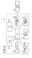
- Fig. 4 shows a schematic electrical configuration of a computer apparatus 20 that can function as the knit design apparatus 10 of Fig. 3.
- a CPU 21 functions as the knit design apparatus 10 of Fig. 3 according to programs previously stored in a ROM 22 or programs deployed in a RAM 23.
- An input device 24 receives instructions or operations from the designer, serving as a part of the data-input means 14 or the knitted fabric design inputting means 17 of Fig. 3.
- a keyboard or a pointing device such as a mouse, a trackball, and a pen tablet can be used as the input device 24.
- the images of a knitting stitch or a knitted fabric are processed in an image-processing device 25.
- a hard disk device 26 stores programs deployed in the RAM 23 or stores image data of a knitting yarn, serving as the knitting yarn image storing means 12 of Fig. 3.
- An external storing device 27, to/from which a recording medium is attached/removed, is used to deliver data for making a knitted fabric or deliver programs or image data.
- Data or programs can be downloaded from an information communication network such as the internet via a communication adaptor 28.
- the images outputted from the image-processing device 25 are displayed in a display device 29 corresponding to the image displaying means 11 of Fig. 3.
- Fig. 5 shows a basic shape 30 of a knitting stitch loop to which this embodiment is directed.
- the basic shape 30 is a knitting stitch shape formed with a basic knitting operation that is made by displacing a knitting needle to the knitting position in a flat knitting machine, and constitutes a front stitch or a back stitch of so-called Jersey stitches.
- the basic shape 30 is made of a needle loop, which is a peak portion of a loop formed by being pulled by a needle, and a sinker loop, which is a trough portion of a loop formed by being held by a sinker.
- one unit is constituted by arranging the peak portion of a loop at the center of the unit, and halves of the trough portion on both ends of the peak portion of a loop.
- knitting stitch loops that are continuous in the course direction can be expressed.
- the knitting stitch loops that are continuous in the course direction are joined while being displaced in the wale direction, which is the direction orthogonal to the course direction, and the upper and lower relationship of the portion in which the knitting stitch loops are overlapped are processed according to a predetermined rule, then the knitted fabric made by a flat knitting machine can be simulated and displayed.
- the central line 31 of the knitting yarn forming one unit of a knitting stitch loop of the basic shape 30 has line symmetry with respect to the symmetry line 32 that traverses the center of both the ends.
- Nine control points 1 ⁇ to 9 ⁇ are set along the central line 31, and thus the shape of the knitting stitch loop can be represented by the positional coordinates of the control points 1 ⁇ to 9 ⁇ .
- the manner in which the knitting stitch loops look when they are overlapped or the limit of the line width on which the transformation state of the mesh is set can be defined based on the control points.
- the line width is limited so that the knitting yarn is rendered to be narrow because the knitting yarn is hooked.
- the number of the control points is not limited to nine. An increase of the number of the control points may make it possible to handle knitting stitch loops with more complex shape.
- the basic shape of the knitting yarn also includes the case where a knitting needle is not displaced and held at a miss-stitch position so that a loop is not formed (hereinafter, referred to as "miss") .
- miss a knitting needle is not displaced and held at a miss-stitch position so that a loop is not formed
- the knitting yarn looks different.
- Table 3 includes the case where the shape of the previous course in knitting is miss, and this is the case where a knitting yarn is hooked with a knitting needle carrying no knitting stitch loop.
- the knitting yarn is rendered with the actual width.
- the limit values are set on both sides or one side, taking one stitch as a unit.
- the knitting yarn is rendered with the size of the limit value.
- the knitting yarn is rendered with the actual yarn width.
- the actual size of one stitch depends on the rendering resolution or the gauge of the flat knitting machine, so that it is calculated at the time of rendering.
- the basic shape 30 shown in Fig. 5 corresponds to the knit shown in Table 2.
- the control 1 ⁇ , which is the starting point, and the control point 9 ⁇ , which is the end point, are opposite ends in the trough portion, and the control 5 ⁇ is the midpoint of the starting point and the end point, that is, the center of the entire shape and also the center of the peak portion.
- a plurality of control points 2 ⁇ , (3),and (4), and (6), (7) and (8) are set between the center and the opposite ends of the basic shape 30.
- the control point 3 ⁇ is set at the midpoint of the control points 1 ⁇ and 5 ⁇ .
- the control point 2 ⁇ is set at the midpoint of the control points 1 ⁇ and 3 ⁇ and is set at an arbitrary position on the central line 31.
- the control point 4 ⁇ is set at a potion symmetrical to the control point 2 ⁇ based on the control point 3 ⁇ .
- the control points 8 ⁇ , 7 ⁇ , and 6 ⁇ that are positioned symmetrically to the control points 2 ⁇ , 3 ⁇ , and 4 ⁇ with respect to the symmetry line 32 are set in the same manner.
- Table 2 when knitting stitch loops are arranged in the wale direction, the position of each control point is set such that the control points 2 ⁇ and 8 ⁇ are aligned in the course direction with the control points 4 ⁇ and 6 ⁇ in the preceding course.
- control points 2 ⁇ and 8 ⁇ are arbitrary, and even when knitting stitch loop are aligned, it is not necessary that the control points 2 ⁇ , 8 ⁇ , 4 ⁇ , and 6 ⁇ are aligned in a straight line.
- the knitting stitch loops in the case of miss, knit and tuck are used as the basic shape.
- the control points in the case of miss and tuck are set based on the basic shape 30 of knit. Although the limit of the line width in each control point is described with reference to Tables 1 to 3, when a knitting stitch having a special shape such as hemming stitches is used, a similar table can be prepared.
- the control points of each knitting stitch loop are calculated based on the knitting data of a knitted fabric to be simulated. For knitting stitch loops different from the basic shapes, such as miss, knit or tuck, the position of each control point is displaced relatively.
- the central line connecting these control points is subjected to spline approximation so as to calculate rendered points on the central line that has been subj ected to spline approximation.
- the number of rendered points per unit of a knitting stitch loop is not fixed, but depends on, for example, the loop length.
- the length between the neighboring rendered points is a length of one section of the transformed meshes 3, and the shape of the transformed meshes 3 is determined.
- Square meshes 2 into which the image data 1 of a knitting yarn is divided are also prepared corresponding to the length between the rendered points.
- the length of one section of the meshes 2 is the same as the length between the neighboring rendered points.
- the knitting yarn of the knitting yarn image data 1 corresponding to the meshes 2 is transformed corresponding to the transformed meshes 3.
- the image data 1 of the knitting yarn is used as a yarn having an indefinite length as described above, and the meshes 2 are set sequentially on the knitting yarn image data 1 corresponding to each knitting stitch loop and transformed in accordance with the meshes 3, so that images of knitting stitch loops are generated.
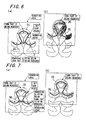
- Figs. 6 and 7 show the concept for rendering, taking the upper and lower relationship into consideration, when rendering a knitting stitch loop image 4 constituting the knitted fabric 6 of Fig. 1(c) as a predetermined loop 35, taking an already rendered loop as a lower loop 36.
- Fig. 6 shows the front stitches
- Fig. 7 shows the back stitches.
- the knitting stitch loop image rendered as the predetermined loop 35 in Figs. 6 (a) and 7 (a) becomes the lower loop 36 when the next knitting stitch loop image is rendered as the predetermined loop 35, as shown in Figs. 6 (b) and 7 (b).
- the knitting stitch loops are rendered sequentially for every course, so that images of the knitted fabric can be generated.
- Table 4 below shows the determination basis of the upper and lower relationship of the basic shape 30 of a knitting stitch loop with respect to the control points when a loop is rendered as the predetermined loop 35. Further, Table 5 shows the determination basis with respect to the lower loop 36. It is determined whether each control point 1 ⁇ to 9 ⁇ of the predetermined loop 35 is positioned above or below the lower loop 36 by determining whether the predetermined loop 35 to be rendered or the lower loop 36 that is below the predetermined loop is a front stitch or a back stitch.
- Predetermined loop control point front stitch back stitch 1 rendering slipping below overwriting rendering 3 overwriting rendering rendering rendering slipping below 7 overwriting rendering rendering slipping below 9 rendering slipping below overwriting rendering
- Lower loop control point front stitch back stitch 5 rendering slipping below overwriting rendering
- the coordinates of the control points or the yarn width are calculated in accordance with displacement or tension caused by the influence of crossing or gathering at the surrounding knitting stitches, so that the state in which a knitting yarn is pulled to the course direction and the wale direction by crossing or gathering of the knitting yarns can be displayed closer to the actual knitted fabric.
- Fig. 8 shows the concept for rendering by transforming the image data 1 of a knitting yarn in accordance with the transformed meshes 3 using the mesh transformation approach.
- Fig. 8 (a) shows one section of the meshes 2 into which the image data 1 of a knitting yarn is divided.
- the image data 1 of a knitting yarn includes a yarn portion 40 and fluffy portions 41 and 42.
- Square meshes 2 are set with respect to the image data 1 of a knitting yarn having a linearly extending shape.
- the vertices of the mesh 2 are taken as P 1 ' , P 2 ', P 3 ' , and P 4 '.
- Fig. 8(b) shows the concept for preparing mesh data in accordance with the transformed meshes 3.
- the vertices P 1 , P 2 , P 3 , and P 4 of the transformed meshes 3 correspond to the vertices P 1 ', P 2 ', P 3 ' , and P 4 ' of mesh 2 shown in Fig. 8 (a) , respectively.
- Each portion in the transformed mesh 3 is rendered along a rendering line 45 shown in Fig. 8 (b) while moving the rendering line 45 from, for example, the line segment connecting the vertex P 2 and the vertex P 3 to the line segment connecting the vertex P 1 and the vertex P 4 .
- the data of pixels for rendering is prepared according to the image data of pixels along a straight line corresponding to the rendering line 45 while moving the straight line from the line segment connecting the vertex P 2 ' and the vertex P 3 ' of the mesh 2 of Fig. 8 (a) to the line segment connecting the vertex P 1 ' and the vertex P 4 ' .
- a shadow portion 46 of a yarn is added to the image data of the knitting yarn.
- the rendering line 45 is a line segment connecting a point L n and a point L n+1 in the transformed mesh 3.
- the inclination of the line segment is obtained based on the positions of the point L n and the point L n+1 , the position on which a shadow is located is determined based on that value, and the shadow portion 46 of the yarn is set.
- the shadow portion 46 of the yarn can be limited to, for example, an arbitrary range on the lower side.
- the level value can be calculated based on the inclination of the points L n and L n+1 , and reflected at the time of mesh rendering. Rendering is performed either on an already rendered yarn or slipping below, depending on the height information of the points L n and L n+1 .
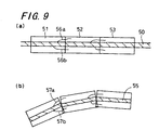
- Fig. 9 shows the concept using segment division disclosed in JP-A 7-70890 and the reason why it is difficult to render a knitting stitch loop with fluffiness or the like reflected.
- image data 50 of a knitting yarn is divided into segments 51, 52, and 53 as shown in Fig. 9 (a) , and synthesized as a part of a knitting stitch loop 55 as shown in Fig. 9(b).
- fluffy portions 56a and 56b are present in an overlapped portion between the segments 51, 52 and 53 of Fig. 9 (a) , reproduction thereof is such that they are cut, broken or curved at the border of the segments, as seen in fluffy portions 57a and 57b, as shown in Fig. 9(b).
- FIG. 11 shows an example of a texture pattern knitted fabric obtained with the image data 60 of the knitting yarn shown in Fig. 10. A texture pattern in which gathering is combined and crossing is formed is shown.
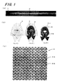
- Fig. 12 shows knitting yarn image data 70 of a fancy yarn called, for example, a loop yarn and a knitted fabric 71 that is simulated and displayed.
- a part of a fiber constituting the yarn projects outward in the form of a loop.
- the portion of the loop or the like that projects outward is treated as a fluffy portion, so that the knitted fabric can be simulated such that its feeling and the like can be reproduced faithfully.
- a nep yarn as a fancy yarn.
- the shapes of the loops projecting outward are irregular, and do not necessarily have definite periodic patterns. In such a case, it is preferable to store image data of a section as long as possible.
- Fig. 13 shows examples of knitted fabrics with texture patterns obtained with the image data 70 of a knitting yarn.
- the transformation state of the mesh is set based on the data for making a knitted fabric.
- the image data of a knitting yarn in which a linearly extending state is divided into a plurality of meshes having a predetermined shape is transformed in accordance with the transformation state that goes along the knitting stitch loop for each mesh.
- the overlapped portion generated by joining of knitting stitch loops is displayed on the upper side or the lower side according to a predetermined rule, so that the feel of the knitting yarn can be reflected on the knitting stitch loop constituting the knitted fabric, and images in which the feeling of the simulated knitted fabric is closer to that of a knitted fabric made of an actual knitting yarn can be displayed.
- the shape of the knitting stitch loop is displayed with the coordinates of a plurality of control points.
- these coordinates are set on the predetermined reference line of the knitting yarn.
- a shape of a knitting stitch loop different from the basic shape can be handled by displacing the position of each control potion relatively, and the transformation state of the mesh is set based on information such as whether or not there is a limitation regarding the line width that can be designed for each control point, or the size of the limit value. Therefore, the transformation states of meshes that can be used for various knitting stitch loop shapes can be set.
- one unit is constituted by one peak portion and two halves of a trough portion, the peak portion being sandwiched by the two halves of the trough portion.
- Control points are set at a plurality of points, that is, at the opposite ends of one unit, the center, and between the center and the opposite ends, and it is possible to designate whether rendering is performed on the upper side of the earlier knitted knitting stitch loop or on the lower side thereof for each control point. Therefore, the shape of a knitting stitch loop and the upper and lower relationship at the time of overlapping can be displayed using the control points.
- the image data of a knitting yarn is divided into meshes such that fluffy portions are also included, so that even in the transformation of the mesh shape corresponding to a knitting stitch loop, fluffiness can be reproduced and the feeling of the knitted fabric made of a fluffy knitting yarn can be simulated reliably.
- a knitted fabric using a knitting yarn in which at least one of the shape, the color and the fluffy state changes over a section having a predetermined length can be displayed with images in which the knitted fabric is simulated with the feeling of such a knitting yarn used exhibited.
- a knitted fabric is designed by aligning the shapes of various knitting stitch loops previously prepared, so that the design can be changed rapidly in the middle of the process, and the knitted fabric finally can be simulated with images with the feeling close to that of the actual knitted fabric.
- the shape of a knitting stitch loop in use for designing a knitted fabric is generated by simulation in which image data of a linear knitting yarn is transformed in accordance with the transformation state that goes along the knitting stitch loop. Therefore, the image data of a knitting yarn can be utilized from the stage of designing the knitted fabric, and the knitted fabric can be simulated with natural representation without sense of incongruity as a whole.
- a knitted fabric can be simulated with images with the feeling close to that of the actual knitted fabric by executing a program on a computer.
- the image data of a linearly extending knitting yarn is stored in the knitting yarn image storing means, and the image data of the knitting yarn is divided into a plurality of meshes having a predetermined shape by the mesh dividing means.
- the shape setting means sets a transformation state of the meshes such that the meshes are transformed along each knitting stitch loop shape constituting the knitted fabric.
- the knitted fabric simulation means simulates a knitted fabric with images by transforming the image data of the knitting yarn so as to be along each knitting stitch loop for each mesh and displaying the portion in which the knitting stitch loops are overlapped on the upper side or the lower side according to a predetermined rule. Therefore, the knitted fabric can be displayed with the feeling as if the knitted fabric is actuallymade of that knitting yarn.
- the images of the knitted fabric can be displayed by simulation with the feeling obtained when actually knitting with the knitting yarn.
- a knitted fabric can be simulated with images, using a knitting yarn selected from a plurality of kinds, so that the difference in the feeling between knitted fabrics due to the difference of the knitting yarn can be easily compared.
Landscapes
- Engineering & Computer Science (AREA)
- Physics & Mathematics (AREA)
- Theoretical Computer Science (AREA)
- General Physics & Mathematics (AREA)
- Geometry (AREA)
- Software Systems (AREA)
- Computer Graphics (AREA)
- Textile Engineering (AREA)
- Computer Hardware Design (AREA)
- Evolutionary Computation (AREA)
- General Engineering & Computer Science (AREA)
- Knitting Machines (AREA)
- Knitting Of Fabric (AREA)
- Treatment Of Fiber Materials (AREA)
Applications Claiming Priority (3)
| Application Number | Priority Date | Filing Date | Title |
|---|---|---|---|
| JP2001310559 | 2001-10-05 | ||
| JP2001310559 | 2001-10-05 | ||
| PCT/JP2002/010355 WO2003032203A1 (fr) | 2001-10-05 | 2002-10-04 | Procede et dispositif de conception d'un tricot |
Publications (3)
| Publication Number | Publication Date |
|---|---|
| EP1452985A1 true EP1452985A1 (fr) | 2004-09-01 |
| EP1452985A4 EP1452985A4 (fr) | 2009-03-18 |
| EP1452985B1 EP1452985B1 (fr) | 2010-12-15 |
Family
ID=19129509
Family Applications (1)
| Application Number | Title | Priority Date | Filing Date |
|---|---|---|---|
| EP02800765A Expired - Lifetime EP1452985B1 (fr) | 2001-10-05 | 2002-10-04 | Procede et dispositif de conception d'un tricot |
Country Status (7)
| Country | Link |
|---|---|
| US (1) | US6880367B2 (fr) |
| EP (1) | EP1452985B1 (fr) |
| JP (1) | JP4079883B2 (fr) |
| KR (1) | KR100684863B1 (fr) |
| CN (1) | CN1310176C (fr) |
| DE (1) | DE60238634D1 (fr) |
| WO (1) | WO2003032203A1 (fr) |
Cited By (10)
| Publication number | Priority date | Publication date | Assignee | Title |
|---|---|---|---|---|
| EP1616984A1 (fr) * | 2003-04-04 | 2006-01-18 | Shima Seiki Manufacturing Limited | Procede et dispositif de conception de tricot |
| EP1720127A4 (fr) * | 2004-02-03 | 2009-03-18 | Shima Seiki Mfg | Dispositif de creation d'images, procede de creation d'images et programme de creation d'images |
| EP1577799A4 (fr) * | 2002-12-03 | 2009-04-01 | Shima Seiki Mfg | Procede de simulation et systeme de simulation d'image de fils torsades |
| EP2164049A1 (fr) * | 2007-06-05 | 2010-03-17 | Shima Seiki Manufacturing., Ltd. | Appareil de simulation de pliage de vêtements tricotés, procédé de simulation et support de stockage |
| EP2189560A1 (fr) * | 2007-09-10 | 2010-05-26 | Shima Seiki Manufacturing., Ltd. | Dispositif et procede de debogage de conception de tricot et programme de debogage associe |
| EP2420977A1 (fr) * | 2010-08-17 | 2012-02-22 | Feintool Intellectual Property AG | Procédé de prévision ou de détermination de l'introduction dans une pièce découpée |
| CN102855345A (zh) * | 2011-07-02 | 2013-01-02 | H.斯托尔两合公司 | 用于线圈描绘的方法和装置 |
| EP1674601A4 (fr) * | 2003-10-15 | 2013-04-10 | Shima Seiki Mfg | Dispositif, procede et programme permettant de simuler une boucle |
| WO2017041191A1 (fr) | 2015-09-10 | 2017-03-16 | Uster Technologies Ag | Prévision de l'apparence d'une surface textile |
| US10410380B2 (en) | 2016-06-29 | 2019-09-10 | Cornell University | Image rendering utilizing procedural yarn model generated in multi-stage processing pipeline |
Families Citing this family (30)
| Publication number | Priority date | Publication date | Assignee | Title |
|---|---|---|---|---|
| GB2399095A (en) * | 2003-03-07 | 2004-09-08 | Lee Sara Corp | Electronic patterning on a knitting machine |
| US7197371B2 (en) * | 2003-03-31 | 2007-03-27 | Shima Seiki Manufacturing, Ltd. | Method and device for knit design |
| KR101014192B1 (ko) * | 2003-04-15 | 2011-02-14 | 가부시키가이샤 시마세이키 세이사쿠쇼 | 니트 디자인 방법과 그 장치 및 프로그램 |
| JP2005015958A (ja) * | 2003-06-26 | 2005-01-20 | Shima Seiki Mfg Ltd | 編地見本の作成方法、ニットデザイン方法、糸径測定装置、及び編地見本の作成装置 |
| JP4163130B2 (ja) * | 2004-02-17 | 2008-10-08 | 株式会社島精機製作所 | インターシャ柄の編成方法と編地、ニットデザイン装置、及び編成プログラム |
| JP4597586B2 (ja) * | 2004-06-07 | 2010-12-15 | 株式会社島精機製作所 | メランジ糸の糸画像作成装置と糸画像作成方法及びそのプログラム |
| JP4366321B2 (ja) * | 2005-02-18 | 2009-11-18 | 株式会社島精機製作所 | ニット製品のデザイン装置とデザイン方法、およびそのプログラム |
| EP1900862B1 (fr) * | 2005-05-27 | 2014-09-03 | Shima Seiki Manufacturing., Ltd. | Dispositif, procede et programme de simulation de tricot |
| WO2007013296A1 (fr) * | 2005-07-28 | 2007-02-01 | Shima Seiki Manufacturing, Ltd. | Système de simulation de boucle, son procédé et son programme |
| JP4693555B2 (ja) * | 2005-09-02 | 2011-06-01 | 大日本印刷株式会社 | 表面に繊維シートを張り付けた三次元仮想物体に基づく二次元画像生成方法および生成装置 |
| JP5089912B2 (ja) * | 2006-04-25 | 2012-12-05 | 豊田通商株式会社 | 編構造モデル生成プログラム、編構造モデル生成装置、及び編構造モデル生成方法 |
| JP4966003B2 (ja) * | 2006-12-28 | 2012-07-04 | 株式会社島精機製作所 | 布帛パターンの作成装置と作成方法、作成プログラム |
| WO2009039668A1 (fr) * | 2007-09-28 | 2009-04-02 | Smartpatterns Inc. | Système et procédé de conception d'objets cousus |
| US7460927B1 (en) * | 2007-12-21 | 2008-12-02 | Freeman Industrial Co., Ltd. | Method of manufacturing knitted fabrics |
| EP2226735A4 (fr) | 2007-12-27 | 2014-05-07 | Shima Seiki Mfg | Dispositif de simulation de tricot et procédé de correction de la torsion du fil dans une simulation de tricot |
| JP5381580B2 (ja) * | 2009-05-13 | 2014-01-08 | 大日本印刷株式会社 | 織物データ生成装置、織物データ生成方法、プログラム、織物布地調エンボス版製造装置、織物布地調エンボス版製造方法、及び織物布地調シートの製造方法 |
| JP5587132B2 (ja) * | 2010-10-19 | 2014-09-10 | キヤノン株式会社 | 画像処理装置、画像処理方法 |
| US8726701B2 (en) * | 2011-03-17 | 2014-05-20 | The Moret Group | Method of making a knit apparel with a tie dyed appearance and an apparel made by the method |
| JP5732321B2 (ja) * | 2011-06-08 | 2015-06-10 | 株式会社島精機製作所 | ニットデザイン方法および装置 |
| CN102864566B (zh) * | 2012-09-29 | 2014-02-12 | 加宝利服装有限公司 | 织物制备方法、制备控制方法、制备控制装置和制备系统 |
| KR101401345B1 (ko) * | 2012-12-27 | 2014-05-29 | 주식회사 무크 | 특정 좌표 이미지를 이용하여 제품 디자인을 구현하는 디지털 전자 장치 |
| JP6029515B2 (ja) * | 2013-03-29 | 2016-11-24 | 株式会社島精機製作所 | パターン作成装置及びパターン作成方法 |
| CN106066898B (zh) * | 2015-04-21 | 2020-03-06 | 艺能国际发展有限公司 | 三维全成型针织衫及产生其三维针织纸样的方法和系统 |
| US9695529B2 (en) * | 2015-04-21 | 2017-07-04 | Artlink International Development Limited | Knitted outer covering and a method and system for making three-dimensional patterns for the same |
| US10995433B1 (en) * | 2017-08-31 | 2021-05-04 | Apple Inc. | Custom fabric cases for electronic devices |
| US10613710B2 (en) * | 2017-10-22 | 2020-04-07 | SWATCHBOOK, Inc. | Product simulation and control system for user navigation and interaction |
| US11761128B2 (en) | 2018-03-17 | 2023-09-19 | Drexel University | Topology optimization for modeling and prediction of complex fabric structures and properties |
| US10787756B2 (en) * | 2018-07-24 | 2020-09-29 | Bolt Threads Inc. | Custom sizing system and methods for a knitted garment having radial symmetry |
| US10988873B2 (en) * | 2019-04-08 | 2021-04-27 | Pai Lung Machinery Mill Co., Ltd. | Fabric file release system for automatically calibrating a circular knitting machine |
| US11859321B2 (en) * | 2021-03-31 | 2024-01-02 | Drexel University | Modular tool for design of self-folding knit fabrics |
Citations (2)
| Publication number | Priority date | Publication date | Assignee | Title |
|---|---|---|---|---|
| US5208901A (en) * | 1991-06-24 | 1993-05-04 | Brother Kogyo Kabushiki Kaisha | Graphic image drawing device |
| US6018349A (en) * | 1997-08-01 | 2000-01-25 | Microsoft Corporation | Patch-based alignment method and apparatus for construction of image mosaics |
Family Cites Families (16)
| Publication number | Priority date | Publication date | Assignee | Title |
|---|---|---|---|---|
| US1231235A (en) * | 1914-08-20 | 1917-06-26 | Lewis B Stillwell | Railway-car construction. |
| JPS54127230A (en) | 1978-03-27 | 1979-10-03 | Nippon Telegr & Teleph Corp <Ntt> | Picture shape converter |
| JPS6071748A (ja) | 1983-09-27 | 1985-04-23 | 株式会社島アイデア・センタ− | 柄情報の記録装置 |
| US4588546A (en) * | 1984-08-27 | 1986-05-13 | The Goodyear Tire & Rubber Company | Wire coating process |
| DE3630828A1 (de) * | 1986-09-10 | 1988-03-24 | Stoll & Co H | Einrichtung zum darstellen und aufbereiten von mittels einer flachstrickmaschine herzustellenden strickmustern |
| US5245587A (en) * | 1990-12-14 | 1993-09-14 | Hutson William H | Multi-dimensional signal processing and display |
| GB2252987A (en) * | 1991-02-19 | 1992-08-26 | Impiz Pty Ltd | Imitation weatherboarding |
| JP2656405B2 (ja) * | 1991-09-17 | 1997-09-24 | 旭化成工業株式会社 | ニットデザインシステムおよびその編成データの作成方法 |
| US5246854A (en) * | 1991-12-16 | 1993-09-21 | The United States Of America As Represented By The Secretary Of Agriculture | Attached growth biological reactor |
| US5557527A (en) * | 1993-08-31 | 1996-09-17 | Shima Seiki Manufacturing Ltd. | Knit design system and a method for designing knit fabrics |
| JP2631946B2 (ja) | 1993-08-31 | 1997-07-16 | 株式会社島精機製作所 | ニットデザインシステム |
| JPH09111620A (ja) * | 1995-10-12 | 1997-04-28 | Tsudakoma Corp | 編地デザインシステムにおける編目画像の表示方法 |
| JP3325168B2 (ja) * | 1995-10-16 | 2002-09-17 | 株式会社島精機製作所 | ニットデザイン方法とニットデザイン装置 |
| DE19901542C2 (de) * | 1999-01-16 | 2002-10-10 | Stoll & Co H | Einrichtung zum Entwurf von auf einer Strick- oder Wirkmaschine hergestellten Maschenerzeugnissen |
| JP2001133962A (ja) * | 1999-11-02 | 2001-05-18 | Advantest Corp | 部分一括転写露光用マスクデータの作成方法及びそれによる露光方法 |
| DE50113866D1 (de) * | 2001-10-06 | 2008-05-29 | Stoll & Co H | Verfahren und Einrichtung zum Entwurf von auf eineGestricken |
-
2002
- 2002-10-04 WO PCT/JP2002/010355 patent/WO2003032203A1/fr active Application Filing
- 2002-10-04 CN CNB02822471XA patent/CN1310176C/zh not_active Expired - Lifetime
- 2002-10-04 EP EP02800765A patent/EP1452985B1/fr not_active Expired - Lifetime
- 2002-10-04 US US10/491,538 patent/US6880367B2/en not_active Expired - Fee Related
- 2002-10-04 DE DE60238634T patent/DE60238634D1/de not_active Expired - Lifetime
- 2002-10-04 KR KR1020047005031A patent/KR100684863B1/ko active IP Right Grant
- 2002-10-04 JP JP2003535100A patent/JP4079883B2/ja not_active Expired - Lifetime
Patent Citations (2)
| Publication number | Priority date | Publication date | Assignee | Title |
|---|---|---|---|---|
| US5208901A (en) * | 1991-06-24 | 1993-05-04 | Brother Kogyo Kabushiki Kaisha | Graphic image drawing device |
| US6018349A (en) * | 1997-08-01 | 2000-01-25 | Microsoft Corporation | Patch-based alignment method and apparatus for construction of image mosaics |
Non-Patent Citations (4)
| Title |
|---|
| HUA ZHONG ET AL: "Realistic and efficient rendering of free-form knitwear" JOURNAL OF VISUALIZATION AND COMPUTER ANIMATION WILEY UK, vol. 12, no. 1, February 2001 (2001-02), pages 13-22, XP002512447 ISSN: 1049-8907 * |
| MEISSNER M ET AL: "The art of knitted fabrics, realistic and physically based modelling of knitted patterns" COMPUTER GRAPHICS FORUM BLACKWELL PUBLISHERS FOR EUROGRAPHICS ASSOC UK, vol. 17, no. 3, 1998, pages C355-C362 , C3, XP003019145 ISSN: 0167-7055 * |
| See also references of WO03032203A1 * |
| XU Y-Q ET AL: "PHOTOREALISTIC RENDERING OF KNITWEAR USING THE LUMISLICE" COMPUTER GRAPHICS. SIGGRAPH 2001. CONFERENCE PROCEEDINGS. LOS ANGELES, CA, AUG. 12 - 17, 2001; [COMPUTER GRAPHICS PROCEEDINGS. SIGGRAPH], NEW YORK, NY : ACM, US, 12 August 2001 (2001-08-12), pages 391-398, XP001049910 ISBN: 978-1-58113-374-5 * |
Cited By (16)
| Publication number | Priority date | Publication date | Assignee | Title |
|---|---|---|---|---|
| EP1577799A4 (fr) * | 2002-12-03 | 2009-04-01 | Shima Seiki Mfg | Procede de simulation et systeme de simulation d'image de fils torsades |
| EP1616984A4 (fr) * | 2003-04-04 | 2006-07-12 | Shima Seiki Mfg | Procede et dispositif de conception de tricot |
| US7330772B2 (en) | 2003-04-04 | 2008-02-12 | Shima Seiki Manufacturing Limited | Knit design method and apparatus |
| EP1616984A1 (fr) * | 2003-04-04 | 2006-01-18 | Shima Seiki Manufacturing Limited | Procede et dispositif de conception de tricot |
| EP1674601A4 (fr) * | 2003-10-15 | 2013-04-10 | Shima Seiki Mfg | Dispositif, procede et programme permettant de simuler une boucle |
| EP1720127A4 (fr) * | 2004-02-03 | 2009-03-18 | Shima Seiki Mfg | Dispositif de creation d'images, procede de creation d'images et programme de creation d'images |
| EP2164049A1 (fr) * | 2007-06-05 | 2010-03-17 | Shima Seiki Manufacturing., Ltd. | Appareil de simulation de pliage de vêtements tricotés, procédé de simulation et support de stockage |
| EP2164049A4 (fr) * | 2007-06-05 | 2011-10-12 | Shima Seiki Mfg | Appareil de simulation de pliage de vêtements tricotés, procédé de simulation et support de stockage |
| EP2189560A1 (fr) * | 2007-09-10 | 2010-05-26 | Shima Seiki Manufacturing., Ltd. | Dispositif et procede de debogage de conception de tricot et programme de debogage associe |
| EP2189560A4 (fr) * | 2007-09-10 | 2011-12-14 | Shima Seiki Mfg | Dispositif et procede de debogage de conception de tricot et programme de debogage associe |
| EP2420977A1 (fr) * | 2010-08-17 | 2012-02-22 | Feintool Intellectual Property AG | Procédé de prévision ou de détermination de l'introduction dans une pièce découpée |
| CN102855345A (zh) * | 2011-07-02 | 2013-01-02 | H.斯托尔两合公司 | 用于线圈描绘的方法和装置 |
| EP2549003A1 (fr) * | 2011-07-02 | 2013-01-23 | H. Stoll GmbH & Co. KG | Procédé et dispositif destinés à la représentation de mailles |
| CN102855345B (zh) * | 2011-07-02 | 2015-11-18 | H.斯托尔两合公司 | 用于线圈描绘的方法和装置 |
| WO2017041191A1 (fr) | 2015-09-10 | 2017-03-16 | Uster Technologies Ag | Prévision de l'apparence d'une surface textile |
| US10410380B2 (en) | 2016-06-29 | 2019-09-10 | Cornell University | Image rendering utilizing procedural yarn model generated in multi-stage processing pipeline |
Also Published As
| Publication number | Publication date |
|---|---|
| EP1452985B1 (fr) | 2010-12-15 |
| CN1310176C (zh) | 2007-04-11 |
| CN1585950A (zh) | 2005-02-23 |
| KR100684863B1 (ko) | 2007-02-20 |
| WO2003032203A1 (fr) | 2003-04-17 |
| KR20040041671A (ko) | 2004-05-17 |
| JPWO2003032203A1 (ja) | 2005-01-27 |
| JP4079883B2 (ja) | 2008-04-23 |
| EP1452985A4 (fr) | 2009-03-18 |
| DE60238634D1 (de) | 2011-01-27 |
| US6880367B2 (en) | 2005-04-19 |
| US20050039495A1 (en) | 2005-02-24 |
Similar Documents
| Publication | Publication Date | Title |
|---|---|---|
| US6880367B2 (en) | Knit design method and device | |
| US6895787B2 (en) | Knit design method and apparatus | |
| KR101099609B1 (ko) | 자수 데이터 작성장치와 자수 데이터 작성방법 및 자수 데이터 작성 프로그램을 기록한 컴퓨터로 읽을 수 있는 매체 | |
| EP0853153B2 (fr) | Système de conception de tricot pour concevoir des étoffes tricotées | |
| KR101078215B1 (ko) | 니트 디자인 방법 및 장치 | |
| CN112131724A (zh) | 一种针织成形产品的三维设计仿真系统与方法 | |
| JP4408813B2 (ja) | 撚り糸画像のシミュレーション方法および装置 | |
| JP4890036B2 (ja) | ニットデータ作成方法及び装置並びにプログラム | |
| WO2008152931A1 (fr) | Procédé de simulation de tricots, appareil pour le procédé, et support de stockage | |
| JP7204583B2 (ja) | ニットデザインシステム | |
| JP5800530B2 (ja) | ニットデザイン装置とニットデザイン方法 | |
| EP2042631B1 (fr) | Dispositif de simulation, procédé de simulation et programme de simulation de tissu tubulaire | |
| JP2000027055A (ja) | デザイン装置 |
Legal Events
| Date | Code | Title | Description |
|---|---|---|---|
| PUAI | Public reference made under article 153(3) epc to a published international application that has entered the european phase |
Free format text: ORIGINAL CODE: 0009012 |
|
| 17P | Request for examination filed |
Effective date: 20040503 |
|
| AK | Designated contracting states |
Kind code of ref document: A1 Designated state(s): AT BE BG CH CY CZ DE DK EE ES FI FR GB GR IE IT LI LU MC NL PT SE SK TR |
|
| AX | Request for extension of the european patent |
Extension state: AL LT LV MK RO SI |
|
| A4 | Supplementary search report drawn up and despatched |
Effective date: 20090212 |
|
| 17Q | First examination report despatched |
Effective date: 20090813 |
|
| GRAP | Despatch of communication of intention to grant a patent |
Free format text: ORIGINAL CODE: EPIDOSNIGR1 |
|
| RIC1 | Information provided on ipc code assigned before grant |
Ipc: G06F 17/50 20060101AFI20100322BHEP Ipc: D04B 37/00 20060101ALI20100322BHEP |
|
| GRAS | Grant fee paid |
Free format text: ORIGINAL CODE: EPIDOSNIGR3 |
|
| GRAA | (expected) grant |
Free format text: ORIGINAL CODE: 0009210 |
|
| AK | Designated contracting states |
Kind code of ref document: B1 Designated state(s): DE ES FR GB IT |
|
| REG | Reference to a national code |
Ref country code: GB Ref legal event code: FG4D |
|
| REF | Corresponds to: |
Ref document number: 60238634 Country of ref document: DE Date of ref document: 20110127 Kind code of ref document: P |
|
| PG25 | Lapsed in a contracting state [announced via postgrant information from national office to epo] |
Ref country code: ES Free format text: LAPSE BECAUSE OF FAILURE TO SUBMIT A TRANSLATION OF THE DESCRIPTION OR TO PAY THE FEE WITHIN THE PRESCRIBED TIME-LIMIT Effective date: 20110326 |
|
| PLBE | No opposition filed within time limit |
Free format text: ORIGINAL CODE: 0009261 |
|
| STAA | Information on the status of an ep patent application or granted ep patent |
Free format text: STATUS: NO OPPOSITION FILED WITHIN TIME LIMIT |
|
| 26N | No opposition filed |
Effective date: 20110916 |
|
| REG | Reference to a national code |
Ref country code: DE Ref legal event code: R097 Ref document number: 60238634 Country of ref document: DE Effective date: 20110916 |
|
| GBPC | Gb: european patent ceased through non-payment of renewal fee |
Effective date: 20111004 |
|
| REG | Reference to a national code |
Ref country code: FR Ref legal event code: ST Effective date: 20120629 |
|
| PG25 | Lapsed in a contracting state [announced via postgrant information from national office to epo] |
Ref country code: GB Free format text: LAPSE BECAUSE OF NON-PAYMENT OF DUE FEES Effective date: 20111004 Ref country code: FR Free format text: LAPSE BECAUSE OF NON-PAYMENT OF DUE FEES Effective date: 20111102 |
|
| REG | Reference to a national code |
Ref country code: DE Ref legal event code: R079 Ref document number: 60238634 Country of ref document: DE Free format text: PREVIOUS MAIN CLASS: G06F0017500000 Ipc: G06F0030000000 |
|
| PGFP | Annual fee paid to national office [announced via postgrant information from national office to epo] |
Ref country code: IT Payment date: 20210910 Year of fee payment: 20 |
|
| PGFP | Annual fee paid to national office [announced via postgrant information from national office to epo] |
Ref country code: DE Payment date: 20210831 Year of fee payment: 20 |
|
| REG | Reference to a national code |
Ref country code: DE Ref legal event code: R071 Ref document number: 60238634 Country of ref document: DE |