EP1452873A2 - Lineargeschwindigkeitsaufnehmer und Verfahren zur Reduzierung der Nichtlinearität des Sensorausgangssignals - Google Patents
Lineargeschwindigkeitsaufnehmer und Verfahren zur Reduzierung der Nichtlinearität des Sensorausgangssignals Download PDFInfo
- Publication number
- EP1452873A2 EP1452873A2 EP04075466A EP04075466A EP1452873A2 EP 1452873 A2 EP1452873 A2 EP 1452873A2 EP 04075466 A EP04075466 A EP 04075466A EP 04075466 A EP04075466 A EP 04075466A EP 1452873 A2 EP1452873 A2 EP 1452873A2
- Authority
- EP
- European Patent Office
- Prior art keywords
- coil
- spool
- housing
- turns
- opening
- Prior art date
- Legal status (The legal status is an assumption and is not a legal conclusion. Google has not performed a legal analysis and makes no representation as to the accuracy of the status listed.)
- Withdrawn
Links
Images


Classifications
-
- G—PHYSICS
- G01—MEASURING; TESTING
- G01P—MEASURING LINEAR OR ANGULAR SPEED, ACCELERATION, DECELERATION, OR SHOCK; INDICATING PRESENCE, ABSENCE, OR DIRECTION, OF MOVEMENT
- G01P3/00—Measuring linear or angular speed; Measuring differences of linear or angular speeds
- G01P3/42—Devices characterised by the use of electric or magnetic means
- G01P3/50—Devices characterised by the use of electric or magnetic means for measuring linear speed
- G01P3/52—Devices characterised by the use of electric or magnetic means for measuring linear speed by measuring amplitude of generated current or voltage
Definitions
- Linear velocity sensors may play a very important role in the control of any mechanical system motion, or vibration that may be encountered by the mechanical system.
- any mechanical system motion, or vibration that may be encountered by the mechanical system.
- luxury vehicles are expected to provide "premium" performance, such as a smoother, or quieter ride, under a wide range of varying operational conditions.
- adaptive or proactive control may be provided to mechanically tune the suspension system, such as for the vehicle chassis, and/or the engine mounts, to accomplish this premium performance.
- Either an adaptive or a proactive vibration control system needs to sense system motion, such as relative displacements and relative velocities in order to select an appropriate vibration control strategy.
- a "linear relative velocity" sensor is used to provide the mechanical system velocity information for these types of control systems.
- the first technique is somewhat limited since the derivative of the position signal generally introduces an unacceptable high level of noise to the resulting signal, and, consequently, lacks sufficient accuracy for meeting high-performance system requirements.
- the third technique has generally very good noise immunity because of the filtering-effects provided by the integration. However, for this sensing technique to work, the initial condition(s) of the system are required. This would result in additional complexity that incrementally adds to the cost of the sensor. Further, this technique may undesirably introduce relatively large phase delays.
- the second technique for sensing velocity i.e., a direct measurement method, generally provides a versatile design choice to the designer because it avoids the issues concomitant with the first and third sensing techniques.
- One common way to measure relative velocity is to use a sensor made up of a coil and a magnet mounted on a movable plunger.
- the coil is typically made with a uniformly distributed winding. That is, the number of turns is constant along the longitudinal axis of the spool on which the coil is wound.
- the coil voltage output signal should be proportional to the rate of change (e.g., speed) of the flux developed within the coil.
- the output signal indicative of velocity information is undesirably dependent upon the plunger position.
- the coil output signal increases, notwithstanding of a constant positive velocity, e.g., velocity V1.
- the coil output would decrease in the presence of a constant negative velocity -V1. That is, the output level of the signal indicative of velocity varies not just as a function of the actual velocity sensed by the coil but also as a function of plunger position.
- the output signal from the coil varies depending on the travel position of the plunger.
- Another factor for reducing the sensor cost is the ability to package relatively small components within the sensor housing, e.g., the magnet and coil.
- the size of the magnet used in various known configurations may result in a relatively bulky sensor, which is generally undesirable for applications where spacing may be scarce.
- a velocity sensor with an improved linear output range. That is, a sensor having an output signal that varies essentially as function of the actual velocity sensed by the sensor and exhibits reduced sensitivity to plunger position. It would be further desirable to provide in a smaller package a reliable, accurate and relatively inexpensive velocity sensor with an improved linear output range.
- a linear velocity sensor that comprises a ferromagnetic housing including an opening.
- the sensor further comprises a spool disposed in the housing.
- the spool includes a bore for receiving a slidable ferromagnetic rod.
- the ferromagnetic rod may be extendable through the opening in the housing.
- a magnet is mounted at the one end of the rod distal from the opening when the rod is substantially inserted in the bore.
- a coil is wound on the spool.
- the number of turns of the coil is arranged to taperingly increase as the coil progresses from an end of the spool proximate the opening in the housing to the opposite end of the spool.
- the tapering arrangement for the number of turns of the coil is selected to reduce non-linearity of an output signal of the coil indicative of linear velocity.
- the present invention further fulfills the foregoing needs by providing a method for reducing output signal non-linearity in a linear velocity sensor.
- the method allows providing a ferromagnetic housing that includes an opening.
- the method further allows disposing a spool in the housing.
- a slidable ferromagnetic rod is received in a bore in the spool.
- the ferromagnetic rod is extendable through the opening in the housing.
- a magnet is mounted at the one end of the rod distal from the opening when the rod is substantially inserted in the bore.
- a coil is wound on the spool.
- the method allows arranging the number of turns of the coil to taperingly increase as the coil progresses from an end of the spool proximate the opening in the housing to the opposite end of the spool.
- the arrangement for the number of turns of the coil is selected to reduce non-linearity of an output signal of the coil indicative of linear velocity.
- FIG. 2 illustrates an exemplary embodiment of a linear velocity sensor 20 embodying aspects of the present invention.
- a ferromagnetic housing 22 includes an opening 24 for receiving a relatively small, ferromagnetic rod 26 with a magnet 28 mounted on one end of rod 26.
- the opposite end of housing 22 may be closed to the ferromagnetic plunger by the housing of an interface connector 23.
- the housing since the housing is made up of ferromagnetic material, the housing functions as a flux concentrator of the magnetic flux from magnet 28.
- the rod essentially constitutes a plunger slidable or extendable through an axially-extending bore 30 in a spool 32.
- a coil 50 is wound around the spool 32.
- the coil is positioned between the plunger 26 and the housing 22, and, since each of such components is made up of ferromagnetic material, they jointly cooperate to form an electromagnetic magnetic circuit that generates an output signal indicative of velocity in response to slidable movement of the plunger, i.e., the rate of change of flux.
- the inventors of the present invention have innovatively recognized structure and/or techniques for reducing the dependency of the output signal of the linear velocity sensor on plunger position. More particularly, aspects of the present invention allow compensating for the non-linear behavior of the sensor, discussed in the background section of this specification, by configuring the coil as a tapered coil.
- the basic concept is to gradually increase the number of turns per unit length as the plunger travels from an extended position to a retracted position.
- the retracted position corresponds to the position wherein the rod would be fully or nearly fully inserted within the bore 30.
- the increase in number of turns due to the tapering allows compensating for the non-linearity that otherwise would be present in the output signal of the coil. That is, the degree of tapering and more precisely the variation in the number of turns along the axial length of the coil would be chosen to inversely match the signal attenuation encountered in a uniformly wound coil.
- the tapering may be provided to the coil using an appropriate winding technique.
- an appropriate winding technique See U.S. patent application Serial No. , (Attorney Docket No. DP-308238), titled “Method and Apparatus For Winding A Coil" for background information regarding techniques generally referred in the art as bank, progressive, or vocational winding techniques.
- the foregoing application is assigned in common to the same assignee of the present invention, and is herein incorporated by reference.
- the tapering may be formed by building up or stacking a plurality of layers of winding on the generally cylindrical surface of the spool 32.
- Another exemplary embodiment to provide the tapering to the coil would be to configure the spool, such as a spool 32' in FIG. 4, to provide the desired tapering, e.g., by molding, the desired configuration with the spool.
- a separate tapering structure e.g., a wedge 60 (FIG. 5)
- the tapering to the coil may be provided by either a separate structure mounted on the spool or a structure integrally constructed (e.g., by molding) with the spool.
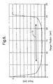
- FIG. 6 is a plot of the output signal from an exemplary velocity sensor with a coil has been tapered in accordance with any of the embodiments discussed in the context of FIGS. 3-5. It will be appreciated that the signal variation as a function of plunger position over an exemplary range (as represented by line 80) is substantially reduced as compared to the output signal of a non-tapered coil (FIG. 1). The plot assumes a constant velocity input.
Landscapes
- Physics & Mathematics (AREA)
- General Physics & Mathematics (AREA)
- Transmission And Conversion Of Sensor Element Output (AREA)
- Measurement Of Length, Angles, Or The Like Using Electric Or Magnetic Means (AREA)
Applications Claiming Priority (2)
| Application Number | Priority Date | Filing Date | Title |
|---|---|---|---|
| US373432 | 1973-06-25 | ||
| US10/373,432 US6876194B2 (en) | 2003-02-26 | 2003-02-26 | Linear velocity sensor and method for reducing non-linearity of the sensor output signal |
Publications (2)
| Publication Number | Publication Date |
|---|---|
| EP1452873A2 true EP1452873A2 (de) | 2004-09-01 |
| EP1452873A3 EP1452873A3 (de) | 2006-01-11 |
Family
ID=32771427
Family Applications (1)
| Application Number | Title | Priority Date | Filing Date |
|---|---|---|---|
| EP04075466A Withdrawn EP1452873A3 (de) | 2003-02-26 | 2004-02-13 | Lineargeschwindigkeitsaufnehmer und Verfahren zur Reduzierung der Nichtlinearität des Sensorausgangssignals |
Country Status (2)
| Country | Link |
|---|---|
| US (1) | US6876194B2 (de) |
| EP (1) | EP1452873A3 (de) |
Families Citing this family (26)
| Publication number | Priority date | Publication date | Assignee | Title |
|---|---|---|---|---|
| US7221150B2 (en) * | 2004-10-14 | 2007-05-22 | Unison Industries Llc | Toothed shell on a variable reluctance speed sensor |
| JP4908180B2 (ja) * | 2006-12-20 | 2012-04-04 | 株式会社東芝 | 動画像符号化装置 |
| US7638892B2 (en) * | 2007-04-16 | 2009-12-29 | Calnetix, Inc. | Generating energy from fluid expansion |
| US8839622B2 (en) * | 2007-04-16 | 2014-09-23 | General Electric Company | Fluid flow in a fluid expansion system |
| US7841306B2 (en) * | 2007-04-16 | 2010-11-30 | Calnetix Power Solutions, Inc. | Recovering heat energy |
| US7463023B1 (en) | 2007-08-02 | 2008-12-09 | Delphi Technologies, Inc. | Non-contacting rotary and linear travel sensor |
| US8102088B2 (en) * | 2008-01-25 | 2012-01-24 | Calnetix Technologies, L.L.C. | Generating electromagnetic forces with flux feedback control |
| WO2010042349A2 (en) * | 2008-10-09 | 2010-04-15 | Calnetix, Inc. | High-aspect-ratio homopolar magnetic actuator |
| US8183854B2 (en) * | 2008-11-07 | 2012-05-22 | Calnetix Technologies, L.L.C. | Measuring linear velocity |
| US8564281B2 (en) * | 2009-05-29 | 2013-10-22 | Calnetix Technologies, L.L.C. | Noncontact measuring of the position of an object with magnetic flux |
| US8674685B2 (en) * | 2009-07-17 | 2014-03-18 | Hamilton Sundstrand Corporation | Magnetic flux oil level sensor for use in aircraft lubrication systems |
| US8378543B2 (en) * | 2009-11-02 | 2013-02-19 | Calnetix Technologies, L.L.C. | Generating electromagnetic forces in large air gaps |
| US8796894B2 (en) | 2010-01-06 | 2014-08-05 | Calnetix Technologies, L.L.C. | Combination radial/axial electromagnetic actuator |
| US8847451B2 (en) | 2010-03-23 | 2014-09-30 | Calnetix Technologies, L.L.C. | Combination radial/axial electromagnetic actuator with an improved axial frequency response |
| US8739538B2 (en) | 2010-05-28 | 2014-06-03 | General Electric Company | Generating energy from fluid expansion |
| US8482174B2 (en) | 2011-05-26 | 2013-07-09 | Calnetix Technologies, Llc | Electromagnetic actuator |
| US9531236B2 (en) | 2011-06-02 | 2016-12-27 | Calnetix Technologies, Llc | Arrangement of axial and radial electromagnetic actuators |
| US8984884B2 (en) | 2012-01-04 | 2015-03-24 | General Electric Company | Waste heat recovery systems |
| US9018778B2 (en) | 2012-01-04 | 2015-04-28 | General Electric Company | Waste heat recovery system generator varnishing |
| US9024460B2 (en) | 2012-01-04 | 2015-05-05 | General Electric Company | Waste heat recovery system generator encapsulation |
| US9407131B2 (en) * | 2012-04-17 | 2016-08-02 | Bwxt Nuclear Operations Group, Inc. | Positional encoder and control rod position indicator for nuclear reactor using same |
| US9024494B2 (en) | 2013-01-07 | 2015-05-05 | Calnetix Technologies, Llc | Mechanical backup bearing arrangement for a magnetic bearing system |
| CN103963738A (zh) * | 2013-02-06 | 2014-08-06 | 现代自动车株式会社 | 非接触式换档锁装置 |
| US9683601B2 (en) | 2013-03-14 | 2017-06-20 | Calnetix Technologies, Llc | Generating radial electromagnetic forces |
| US9559565B2 (en) | 2013-08-22 | 2017-01-31 | Calnetix Technologies, Llc | Homopolar permanent-magnet-biased action magnetic bearing with an integrated rotational speed sensor |
| WO2015033355A2 (en) * | 2013-09-04 | 2015-03-12 | Pricol Limited | Improved sensor for speed, position and direction |
Family Cites Families (14)
| Publication number | Priority date | Publication date | Assignee | Title |
|---|---|---|---|---|
| US3054976A (en) * | 1958-11-18 | 1962-09-18 | Schaevitz Engineering | Differential transformer |
| US3743794A (en) * | 1972-03-02 | 1973-07-03 | Hewlett Packard Co | Translational motion apparatus for the magnetic transducers of a disc memory |
| JPS545984B2 (de) | 1973-04-26 | 1979-03-23 | ||
| US4100480A (en) * | 1976-08-20 | 1978-07-11 | Dataproducts Corporation | Position and velocity sensors |
| US4260914A (en) | 1979-03-28 | 1981-04-07 | Digital Equipment Corporation | Differential linear velocity transducer |
| JPH02156112A (ja) * | 1988-12-08 | 1990-06-15 | Nippon Data Instr Kk | 線型変位検出装置 |
| DE4126586A1 (de) * | 1991-08-12 | 1993-02-18 | Bilstein August Gmbh Co Kg | Sensor in einem schwingungsdaempfer fuer kraftfahrzeuge |
| JPH0526888A (ja) * | 1991-07-19 | 1993-02-02 | Sony Corp | 速度センサ |
| US5698910A (en) * | 1995-12-22 | 1997-12-16 | Eastman Kodak Company | Electromagnetic actuator with position sensor |
| EP0827164A3 (de) * | 1996-08-31 | 1998-11-18 | Toyo Denso Kabushiki Kaisha | Zündspulenvorrichtung für Brennkraftmaschine und Verfahren zum Wickeln einer Zündspule |
| DE19913050A1 (de) * | 1999-03-23 | 2000-09-28 | Fev Motorentech Gmbh | Verfahren zur Erfassung der Position und/oder Bewegungsgeschwindigkeit eines zwischen zwei Schaltstellungen hin und her bewegbaren Stellelements |
| EP1219005A4 (de) | 1999-09-16 | 2012-01-25 | Gm Global Tech Operations Inc | Tachometer und verfahren zur messung der motorgeschwindigkeit |
| JP2001272201A (ja) * | 2000-03-27 | 2001-10-05 | Sony Precision Technology Inc | 位置検出装置 |
| US6310472B1 (en) * | 2000-04-13 | 2001-10-30 | Jacob Chass | Multiple hall effect sensor of magnetic core displacement |
-
2003
- 2003-02-26 US US10/373,432 patent/US6876194B2/en not_active Expired - Fee Related
-
2004
- 2004-02-13 EP EP04075466A patent/EP1452873A3/de not_active Withdrawn
Also Published As
| Publication number | Publication date |
|---|---|
| US6876194B2 (en) | 2005-04-05 |
| US20040164726A1 (en) | 2004-08-26 |
| EP1452873A3 (de) | 2006-01-11 |
Similar Documents
| Publication | Publication Date | Title |
|---|---|---|
| US6876194B2 (en) | Linear velocity sensor and method for reducing non-linearity of the sensor output signal | |
| US5717330A (en) | Magnetostrictive linear displacement transducer utilizing axial strain pulses | |
| KR100833329B1 (ko) | 상대변위 측정 센서가 설치된 댐퍼 | |
| US4401986A (en) | Position sensor and system | |
| EP0209287A1 (de) | Betätigungsvorrichtungen mit variabler Reluktanz, Konstantkraftsteuerung und positionsgebundenen Eigenschaften | |
| EP1964696B1 (de) | Stossdämpfer mit Lagesensor | |
| US5233293A (en) | Sensor for measuring the speed and/or position of a piston in relation to that of the cylinder it moves inside of in a dashpot or shock absorber | |
| US8160774B2 (en) | Vehicular actuator system | |
| US5251729A (en) | Vehicle suspension damper with relative velocity sensor having controlled flux path | |
| US4893699A (en) | Shock absorber | |
| KR100872091B1 (ko) | 상대변위 측정 센서모듈 및 이를 이용한 이동방향 감지방법 | |
| US7308975B2 (en) | Velocity sensing system for a damper | |
| US6714005B2 (en) | Non-contact type displacement sensor apparatus | |
| US4507639A (en) | Inductive position sensor | |
| JP4824023B2 (ja) | 磁気式位置センサ | |
| JPH04272528A (ja) | 振動緩衝装置を備えた緩衝機構 | |
| EP1058094A2 (de) | Magnetischer Geber | |
| US5135251A (en) | Active oscillation damping sensor for measuring relative velocity between body and axle | |
| JP6663086B1 (ja) | 2線式変位センサ装置、及び変位検出システム | |
| US5451870A (en) | Sensor for measuring the difference between the velocity of a cylinder and a piston in a dashpot | |
| GB2164154A (en) | Magnetic velocity sensor | |
| CN102620753B (zh) | 感应式路径测量装置 | |
| EP1422731B1 (de) | Elektrodynamischer Aktuator | |
| EP1835200B1 (de) | Kolbendämpfungsanordnung und Staubrohrunteranordnung mit Geschwindigkeitssensor | |
| JPH02112766A (ja) | 加速度センサ |
Legal Events
| Date | Code | Title | Description |
|---|---|---|---|
| PUAI | Public reference made under article 153(3) epc to a published international application that has entered the european phase |
Free format text: ORIGINAL CODE: 0009012 |
|
| AK | Designated contracting states |
Kind code of ref document: A2 Designated state(s): AT BE BG CH CY CZ DE DK EE ES FI FR GB GR HU IE IT LI LU MC NL PT RO SE SI SK TR |
|
| AX | Request for extension of the european patent |
Extension state: AL LT LV MK |
|
| PUAL | Search report despatched |
Free format text: ORIGINAL CODE: 0009013 |
|
| AK | Designated contracting states |
Kind code of ref document: A3 Designated state(s): AT BE BG CH CY CZ DE DK EE ES FI FR GB GR HU IE IT LI LU MC NL PT RO SE SI SK TR |
|
| AX | Request for extension of the european patent |
Extension state: AL LT LV MK |
|
| 17P | Request for examination filed |
Effective date: 20060711 |
|
| AKX | Designation fees paid |
Designated state(s): DE FR GB |
|
| 17Q | First examination report despatched |
Effective date: 20060831 |
|
| STAA | Information on the status of an ep patent application or granted ep patent |
Free format text: STATUS: THE APPLICATION IS DEEMED TO BE WITHDRAWN |
|
| 18D | Application deemed to be withdrawn |
Effective date: 20090901 |