EP1964696B1 - Stossdämpfer mit Lagesensor - Google Patents
Stossdämpfer mit Lagesensor Download PDFInfo
- Publication number
- EP1964696B1 EP1964696B1 EP08250239A EP08250239A EP1964696B1 EP 1964696 B1 EP1964696 B1 EP 1964696B1 EP 08250239 A EP08250239 A EP 08250239A EP 08250239 A EP08250239 A EP 08250239A EP 1964696 B1 EP1964696 B1 EP 1964696B1
- Authority
- EP
- European Patent Office
- Prior art keywords
- shock
- magnets
- dust tube
- suspension
- module
- Prior art date
- Legal status (The legal status is an assumption and is not a legal conclusion. Google has not performed a legal analysis and makes no representation as to the accuracy of the status listed.)
- Not-in-force
Links
- 230000035939 shock Effects 0.000 title claims description 110
- 239000006096 absorbing agent Substances 0.000 title claims description 34
- 239000000428 dust Substances 0.000 claims description 54
- 239000000725 suspension Substances 0.000 claims description 50
- 238000004891 communication Methods 0.000 claims description 14
- 238000000034 method Methods 0.000 claims description 9
- 230000004044 response Effects 0.000 claims description 6
- 230000003993 interaction Effects 0.000 claims description 5
- 239000012530 fluid Substances 0.000 claims 3
- 230000003247 decreasing effect Effects 0.000 claims 1
- 238000010248 power generation Methods 0.000 description 4
- 230000003044 adaptive effect Effects 0.000 description 3
- 238000006073 displacement reaction Methods 0.000 description 3
- 239000003990 capacitor Substances 0.000 description 2
- 230000004907 flux Effects 0.000 description 2
- 239000000463 material Substances 0.000 description 2
- 230000008859 change Effects 0.000 description 1
- 238000013016 damping Methods 0.000 description 1
- 238000010586 diagram Methods 0.000 description 1
- 238000005516 engineering process Methods 0.000 description 1
- 239000007769 metal material Substances 0.000 description 1
- 238000012986 modification Methods 0.000 description 1
- 230000004048 modification Effects 0.000 description 1
Images


Classifications
-
- B—PERFORMING OPERATIONS; TRANSPORTING
- B60—VEHICLES IN GENERAL
- B60G—VEHICLE SUSPENSION ARRANGEMENTS
- B60G17/00—Resilient suspensions having means for adjusting the spring or vibration-damper characteristics, for regulating the distance between a supporting surface and a sprung part of vehicle or for locking suspension during use to meet varying vehicular or surface conditions, e.g. due to speed or load
- B60G17/015—Resilient suspensions having means for adjusting the spring or vibration-damper characteristics, for regulating the distance between a supporting surface and a sprung part of vehicle or for locking suspension during use to meet varying vehicular or surface conditions, e.g. due to speed or load the regulating means comprising electric or electronic elements
- B60G17/019—Resilient suspensions having means for adjusting the spring or vibration-damper characteristics, for regulating the distance between a supporting surface and a sprung part of vehicle or for locking suspension during use to meet varying vehicular or surface conditions, e.g. due to speed or load the regulating means comprising electric or electronic elements characterised by the type of sensor or the arrangement thereof
- B60G17/01933—Velocity, e.g. relative velocity-displacement sensors
-
- F—MECHANICAL ENGINEERING; LIGHTING; HEATING; WEAPONS; BLASTING
- F16—ENGINEERING ELEMENTS AND UNITS; GENERAL MEASURES FOR PRODUCING AND MAINTAINING EFFECTIVE FUNCTIONING OF MACHINES OR INSTALLATIONS; THERMAL INSULATION IN GENERAL
- F16F—SPRINGS; SHOCK-ABSORBERS; MEANS FOR DAMPING VIBRATION
- F16F9/00—Springs, vibration-dampers, shock-absorbers, or similarly-constructed movement-dampers using a fluid or the equivalent as damping medium
- F16F9/32—Details
- F16F9/3292—Sensor arrangements
-
- F—MECHANICAL ENGINEERING; LIGHTING; HEATING; WEAPONS; BLASTING
- F16—ENGINEERING ELEMENTS AND UNITS; GENERAL MEASURES FOR PRODUCING AND MAINTAINING EFFECTIVE FUNCTIONING OF MACHINES OR INSTALLATIONS; THERMAL INSULATION IN GENERAL
- F16F—SPRINGS; SHOCK-ABSORBERS; MEANS FOR DAMPING VIBRATION
- F16F9/00—Springs, vibration-dampers, shock-absorbers, or similarly-constructed movement-dampers using a fluid or the equivalent as damping medium
- F16F9/32—Details
- F16F9/38—Covers for protection or appearance
-
- B—PERFORMING OPERATIONS; TRANSPORTING
- B60—VEHICLES IN GENERAL
- B60G—VEHICLE SUSPENSION ARRANGEMENTS
- B60G2204/00—Indexing codes related to suspensions per se or to auxiliary parts
- B60G2204/10—Mounting of suspension elements
- B60G2204/11—Mounting of sensors thereon
- B60G2204/112—Mounting of sensors thereon on dampers, e.g. fluid dampers
-
- B—PERFORMING OPERATIONS; TRANSPORTING
- B60—VEHICLES IN GENERAL
- B60G—VEHICLE SUSPENSION ARRANGEMENTS
- B60G2400/00—Indexing codes relating to detected, measured or calculated conditions or factors
- B60G2400/25—Stroke; Height; Displacement
- B60G2400/252—Stroke; Height; Displacement vertical
-
- B—PERFORMING OPERATIONS; TRANSPORTING
- B60—VEHICLES IN GENERAL
- B60G—VEHICLE SUSPENSION ARRANGEMENTS
- B60G2401/00—Indexing codes relating to the type of sensors based on the principle of their operation
- B60G2401/17—Magnetic/Electromagnetic
Definitions
- a shock absorber includes an integrated position sensor that is used to adjust suspension ride height.
- Air suspensions include leveling valves that can be adjusted to change a ride height of the air suspension.
- ride height is set by, and adjusted by, a mechanical linkage that is attached to the leveling valves.
- This mechanical linkage must be manually actuated by an operator to adjust ride height.
- One disadvantage with this system is that the mechanical linkage adds complexity, is labor intensive and increases weight. Additionally, operators do not always set the ride height at a proper level based on vehicle application and/or payload.
- suspensions systems such as adaptive, semi-active, and active suspensions use accelerometers and/or displacement transducers to determine wheel position and wheel velocity. This information is then used to adjust right height as needed.
- accelerometers and displacement transducers increase the cost of the suspension system.
- DE3446411 discloses a sensor device configured to detect the relative position of two parts of a spring strut.
- a shock absorber includes an integrated position sensor that can be used to adjust suspension ride height.
- a rod is movable relative to a shock body along a rod axis
- a dust tube has an inner surface that surrounds an outer surface of the shock body.
- a plurality of magnets is mounted to one of the dust tube and shock body
- an electronic module is mounted to the other of the dust tube and shock body. The electronic module determines a position of the dust tube relative to a position of the shock body based on interaction between the plurality of magnets and the module. Position information is communicated to a suspension control, and suspension ride height is adjusted as needed based on the position information.
- the electronic module comprises a control module that includes a position sensing circuit that determines the position information, and a communication circuit that communicates the position information to the suspension control.
- the communication circuit includes a transceiver for wirelessly communicating position information to a location remote from the shock body, for example.
- the control module includes a coil that interacts with the plurality of magnets to generate power for the position sensing circuit and the communication circuit.
- the control module also includes a power storage device, such as a capacitor, that stores power generated by relative movement between the coil and the plurality of magnets.
- adjacent magnets are axially spaced apart from each other in a direction along the rod axis.
- the position sensing circuit counts the pulses and determines the position information based on the pulses counted.
- the communication circuit communicates the position information to a suspension control, which in turn communicates with a leveling valve to adjust suspension ride height as needed.
- the subject invention provides a simplified method and apparatus for easily adjusting suspension ride height.
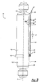
- a shock absorber 10 includes an outer shock body 12, a rod 14 that is movable relative to the shock body 12 along a rod axis A, and a dust tube 16 that protects the shock body 12.
- One of the rod 14 and the shock body 12 is attachable to a vehicle frame or chassis 18 and the other of the rod 14 and shock body 12 is attachable to a wheel or axle component 20.
- the rod 14 is attached to the vehicle chassis 18 via a first mounting bushing 22 and the shock body 12 is attached to an axle component 20 via a second mounting bushing 24.
- the shock body 12 moves with the axle component 20 and the dust tube 16 and rod 14 moves with the vehicle chassis 18.
- a reverse mounting configuration could also be used.
- the rod 14 extends into an interior of the shock body 12 and is coupled to a piston assembly (not shown). Operation of the shock absorber 10 to dampen road load inputs is known and will not be discussed in further detail.
- the shock body 12 includes an outer surface 26 that faces an inner surface 28 of the dust tube 16.
- the shock body 12 is movable relative to the dust tube 16 in response to road load inputs.
- the dust tube 16 is fixed to the rod 14, which is in turn mounted to the vehicle chassis 18.
- the dust tube 16 includes a cup-shaped or base portion 30 at one end that is attached to the rod 14.
- a tubular portion 32 extends from the base portion 30 down a length of the shock body 12.
- the tubular portion 32 has an open end 34 opposite from the base portion 30 such that an end 36 of the shock body 12 extends outwardly from the dust tube 16.
- the inner surface 28 of the dust tube 16 extends from the base portion 30 to the open end 34.
- a plurality of magnets 38 is mounted to the dust tube 16.
- the magnets can be positioned in a wall of the dust tube 16 or can be supported by the inner surface 28 of the dust tube 16.
- the magnets 38 are mounted to the inner surface 28 of the dust tube 16.
- the magnets 38 are axially spaced apart from each other in a direction along the rod axis A.
- the magnets extend generally along an entirety of the length of the inner surface 28, i.e. magnets 38 extend from the base portion 30 to the open end 34; however the magnets could extend only along a portion of the length.
- Positioning multiple magnets along the length of the dust tube 16 provides very accurate positional information.
- Each magnet 38 is spaced apart from an adjacent magnet 38 by a predetermined distance d.
- the predetermined distance d can be generally constant between adjacent magnets 38 or can vary.
- the inner surface 28 of the dust tube 16 has a plurality of magnetic zones with varying magnetic flux density that are separated from each other by non-magnetic zones.
- the dust tube 16 can be made from plastic material, for example, to form the non-magnetic zones; however other materials could also be used.
- a control module 40 is mounted to the outer surface 26 of the shock body 12 at a position near where the rod 14 extends out of the shock body 12.
- the control module 40 is mounted to an end 42 of the shock body 12 that is opposite from the end 36 that extends outwardly of the dust tube 16.
- the control module 40 is an electronic module that includes a coil 44, such as a wound wire coil for example, and a module body 46. Relative movement between the coil 44 and the plurality of magnets 38 generates power for the control module 40. Further, interaction between the coil 44 and magnets 38 can be used to determine a position of the shock absorber 10. This will be discussed in greater detail below.
- the shock absorber 110 includes an outer shock body 112, a rod 114 that is movable relative to the shock body 112 along the rod axis A, and a dust tube 116 that protects the shock body 112.
- one of the rod 114 and the shock body 112 is attachable to the vehicle frame or chassis 18 and the other of the rod 114 and shock body 112 is attachable to a wheel or axle component 20.
- the shock body 112 moves with the axle component 20 and the dust tube 116 and rod 114 moves with the vehicle chassis 18.
- a reverse mounting configuration could also be used.
- the shock body 112 includes an outer surface 126 that faces an inner surface 128 of the dust tube 116.
- the shock body 112 is movable relative to the dust tube 116 in response to road load inputs.
- the dust tube 116 includes a cup-shaped or base portion 130 at one end that is attached to the rod 114.
- a tubular portion 132 extends from the base portion 130 down a length of the shock body 112.
- the tubular portion 132 has an open end 134 opposite from the base portion 130 such that an end 136 of the shock body 112 extends outwardly from the dust tube 116.
- a plurality of magnets 138 is mounted to the outer surface 126 of the shock body 112.
- the magnets 138 can be positioned in a wall of the shock body 112 or each magnet 138 can be separately supported by the outer surface 126 of the shock body.
- all of the magnets 138 are supported on a common polarized strip 180 that is attached as single unit to the outer surface 126 of the shock body 112.
- the strip 180 is made from a non-metallic material and includes polarized magnetic zones Z1 that are separated from each other by non-magnetic zones Z2.
- the magnets 138 are axially spaced apart from each other in a direction along the rod axis A. In the example shown, the magnets 138 extend generally along a significant portion of the length of the shock body 112. This provides very accurate position information. Each magnet 138 is spaced apart from an adjacent magnet 138 by a predetermined distance d. The predetermined distance d can be generally constant between adjacent magnets 138 or can vary. Thus, the shock body 112 includes a plurality of magnetic zones Z1 with varying magnetic flux density that are separated from each other by non-magnetic zones Z2.
- a module 140 is mounted at the open end 134 of the dust tube 116.
- the module 140 generates electrical pulses due to interaction with the magnetic zones.
- the module 140 transmits the electrical pulses to a control module via a wire, for example.
- the module 140 can be embedded within a wall of the dust tube 116 or mounted to the inner surface 28 of the dust tube 116.
- the module 140 is mounted to an end of the dust tube 116 such that the module 140 forms a downward extension portion of the dust tube 116.
- the control module for use with the example of Figure 3 can be located adjacent to, or remotely from, the shock absorber 110.
- the control module receives the electrical pulses and then determines position and/or velocity to control valves that adjust ride height and/or shock damping, such as that shown in Figure 2 which will be discussed in greater detail below. This determination can be done in an ABS computer, an engine computer, or a vehicle body computer, for example.
- the control module 40 for Figure 1 is shown in greater detail in Figure 2 .
- the control module 40 includes a position sensing circuit 48, a communications circuit 50, and a power generation and storage circuit 52.
- the position sensing circuit 48, communications circuit 50, and power generation and storage circuit 52 are associated with the module body 46.
- the position sensing circuit 48 determines a position of the dust tube 16, 116 relative to a position of the shock body 12 and/or the shock position in relation to the vehicle frame or chassis 18.
- the position sensing circuit 48 can be a Magnetoresistor, for example.
- a pulse is generated as the coil 44 passes over each magnet 38, 138.
- the position sensing circuit 48 counts the pulses and determines position information based on the pulses counted.
- the position sensing circuit 48 generates a position signal representative of the determined position information. This position information is used to determine a ride height for a vehicle suspension.
- the communications circuit 50 communicates the position signal to a suspension control module 54, and can use Bluetooth technology, for example.
- the communications circuit 50 includes a transceiver 58 that wirelessly communicates position information to a transceiver or receiving unit 60 associated with the suspension control module 54.
- the power generation and storage circuit 52 generates and regulates power for the control module 40 via interaction between the coil 44 and the magnets 38, 138.
- the power generation and storage circuit 52 includes a storage device 62, such as a capacitor for example, that stores generated power for the control module 40.
- the suspension control module 54 is remote from the control module 40, which is associated with the shock absorber 10.
- the suspension control module 54 is associated with a valve assembly 66 that is used to adjust an adjustable suspension component 68 that is associated with each axle wheel.
- a tandem axle configuration is shown with adjustable suspension components 68a-d at each of the four wheels; however, other types of axle configurations could also be used.
- the valve assembly 66 can comprise a plurality of separate valves, such as one valve associated with each adjustable suspension component 68, or it can be a single valve assembly that communicates with each adjustable suspension component 68.
- the adjustable suspension component can be the shock absorber 10 itself, or could be another adjustable component such as an air spring for example.
- the valve assembly 66 is in communication with a supply 70.
- the valve assembly 66 comprises a solenoid valve.
- the suspension control module 54 generates a control signal that is communicated to the valve assembly 66, which supplies air to, or exhausts air from, the adjustable suspension component 68 to increase or decrease ride height as needed based on position information received from the control module 40.
- a shock absorber 10 is associated with each of the four (4) wheels, i.e. two shock absorbers for the forward-rear axle and two shock absorbers for the rear-rear axle.
- the shock absorber 10 comprises a suspension stop in extension. This is used as a reference point to set suspension ride height.
- position signals from pairs of cross-comer shock absorbers can be averaged together, i.e. the position signals from a driver front corner shock and a passenger rear corner shock would be averaged together, and the position signals from a passenger front corner shock and a driven rear corner shock would be averaged together.
- the suspension control module 54 would use this averaged signal to determine if the valve assembly 66 should remain closed, increase ride height, or decrease ride height.
- the shock absorber with integrated position sensor would operate in a traditional manner, but additional accelerometers, displacement sensors, and associated wiring harnesses are no longer required.
- This integrated sensor could be adapted to work with air springs, air and/or oil struts, and air and/or oil shock absorbers.
- adaptive and semi-active shock absorbers and/or strut modules can be made to be self-powered ( Figure 1 ) such that associated power wiring is no longer necessary.
Landscapes
- Engineering & Computer Science (AREA)
- General Engineering & Computer Science (AREA)
- Mechanical Engineering (AREA)
- Vehicle Body Suspensions (AREA)
- Measurement Of Length, Angles, Or The Like Using Electric Or Magnetic Means (AREA)
Claims (19)
- Stoßdämpferanordnung (10), die Folgendes umfasst:einen Stoßdämpferkörper (12);eine Stange (14), die relativ zu dem Stoßdämpferkörper längs einer Stangenachse beweglich ist, wobei entweder der Stoßdämpferkörper (12) oder die Stange (14) an einer Achsenkomponente (20) montierbar ist und das jeweils Andere des Stoßdämpferkörpers (12) und der Stange (14) an einem Fahrzeug-Chassis (18) montierbar ist;ein Staubrohr (16) mit einer inneren Oberfläche (28), die eine äußere Oberfläche (26) des Stoßdämpferkörpers (12) umgibt, wobei der Stoßdämpferkörper (12) relativ zu dem Staubrohr (16) in Reaktion auf Straßenlasteingaben beweglich ist;mehrere Magneten (38); undein elektronisches Modul (40), wobei das elektronische Modul (40) mit den mehreren Magneten (38) in Wechselwirkung tritt, um eine Position des Staubrohrs (16) relativ zu einer Position des Stoßdämpferkörpers (12) zu bestimmen;dadurch gekennzeichnet, dass die mehreren Magneten (38) entweder an dem Staubrohr (16) oder an dem Stoßdämpferkörper (12) befestigt sind; und das elektronische Modul (40) an dem jeweils Anderen des Staubrohrs (16) und des Stoßdämpferkörpers (12) befestigt ist.
- Stoßdämpferanordnung (10) nach Anspruch 1, wobei wenigstens einige der mehreren Magneten (38) von einem benachbarten Magneten (38) in einer Richtung längs der Stangenachse axial beabstandet sind.
- Stoßdämpferanordnung (10) nach Anspruch 2, wobei das Staubrohr (16) an einem Ende benachbart zu der Stange (14) einen Basisabschnitt (30) aufweist und an einem gegenüberliegenden Ende (34) offen ist, so dass sich der Stoßdämpferkörper (12) von dem Staubrohr in einer Richtung längs der Stangenachse nach außen erstreckt, und wobei sich die innere Oberfläche (28) des Staubrohrs von dem Basisabschnitt (30) zu einem gegenüberliegenden Ende (34) erstreckt, wobei die mehreren Magneten (38) im Wesentlichen auf der gesamten Länge der inneren Oberfläche (28) positioniert sind, wobei jeder Magnet (38) von einem benachbarten Magneten (38) um eine vorgegebene Strecke beabstandet ist.
- Stoßdämpferanordnung (10) nach Anspruch 1, wobei das elektronische Modul (40) ein Steuermodul (40) mit einer Spule (44) und einer Positionserfassungsschaltung (48) umfasst, wobei die Positionserfassungsschaltung (48) ein Positionssignal erzeugt, das an eine Aufhängungssteuerung (54) übermittelt wird.
- Stoßdämpferanordnung (10) nach Anspruch 4, wobei das Steuermodul (40) eine Kommunikationsschaltung (50) umfasst, die das Positionssignal zu der Aufhängungssteuerung (54) übermittelt, und wobei eine Relativbewegung zwischen der Spule (44) und den mehreren Magneten (38) Energie für die Positionserfassungsschaltung (48) und die Kommunikationsschaltung (50) erzeugt.
- Stoßdämpferanordnung (10) nach Anspruch 5, wobei die Aufhängungssteuerung (54) anhand des Positionssignals bestimmt, ob eine Aufhängungshöhe eingestellt werden soll, und ein Steuersignal für die Übermittlung zu einer Höheneinstellventil-Anordnung erzeugt, um die Aufhängungshöhe wie gewünscht einzustellen.
- Stoßdämpferanordnung (10) nach Anspruch 5, wobei die Kommunikationsschaltung (50) einen Sender/Empfänger (58) enthält, der das Positionssignal zu der Aufhängungssteuerung (54) drahtlos übermittelt.
- Stoßdämpferanordnung (10) nach Anspruch 4, wobei das Steuermodul (40) eine Energiespeichervorrichtung enthält, um Energie, die durch die Relativbewegung zwischen der Spule (44) und den mehreren Magneten (38) erzeugt wird, zu speichern.
- Stoßdämpferanordnung (10) nach Anspruch 4, wobei die Positionserfassungsschaltung (48) Impulse zählt, die durch die Relativbewegung zwischen der Spule (44) und den mehreren Magneten (38) erzeugt werden, wenn sich der Stoßdämpferkörper (12) relativ zu dem Staubrohr (16) längs der Stangenachse bewegt, um die Position des Staubrohrs (16) relativ zu dem Stoßdämpferkörper (12) zu bestimmen.
- Stoßdämpferanordnung (10) nach Anspruch 1, wobei die mehreren Magneten (38) an dem Stoßdämpferkörper (12) getragen werden und so positioniert sind, dass sie sich auf einer wesentlichen Länge des Stoßdämpferkörpers (12) erstrecken.
- Stoßdämpferanordnung (10) nach Anspruch 10, wobei die mehreren Magneten (38) durch einen gemeinsamen Streifen (180) getragen werden, der an der äußeren Oberfläche (126) des Stoßdämpferkörpers (112) befestigt ist.
- Verfahren zum Steuern der Aufhängungsfahrhöhe, das die folgenden Schritte umfasst:(a) Vorsehen eines Stoßdämpferkörpers (12), einer Stange (14), die relativ zu dem Stoßdämpferkörper längs einer Stangenachse beweglich ist, und eines Staubrohrs (16), das eine innere Oberfläche (28) besitzt, die eine äußere Oberfläche (26) des Stoßdämpferkörpers (12) umgibt;(b) Montieren mehrerer Magneten (38) an dem Staubrohr (16) oder an dem Stoßdämpferkörper (12),(c) Montieren eines elektronischen Moduls (40) an dem Staubrohr (16) oder dem Stoßdämpferkörper (12);(d) Bestimmen einer Position des Staubrohrs relativ zu einer Position des Stoßdämpferkörpers anhand einer Wechselwirkung zwischen den mehreren Magneten (38) und dem Modul (40);(e) Übermitteln von Positionsinformationen aus dem Schritt (d) zu einer Aufhängungssteuerung (54); und(f) Einstellen der Aufhängungsfahrhöhe anhand der Positionsinformationen des Schrittes (e);dadurch gekennzeichnet, dass im Schritt (b) die mehreren Magneten (38) entweder an dem Staubrohr (16) oder an dem Stoßdämpferkörper (12) montiert werden und im Schritt (c) das elektronische Modul (40) an dem jeweils Anderen des Staubrohrs und des Stoßdämpferkörpers montiert wird.
- Verfahren nach Anspruch 12, wobei das Modul (40) Impulse erzeugt und wobei der Schritt (d) das Zählen der während der Relativbewegung zwischen dem Modul und den mehreren Magneten (38) erzeugten Impulse umfasst, um Positionsinformationen zu bestimmen.
- Verfahren nach Anspruch 12, wobei das Modul (40) ein Steuermodul aufweist, das eine Spule (44) enthält, umfassend das Erzeugen von Energie für das Steuermodul (40) anhand der Relativbewegung zwischen der Spule (44) und den mehreren Magneten.
- Verfahren nach Anspruch 14, das das Speichern der erzeugten Energie in einer Energiespeichervorrichtung (62), die dem Steuermodul (40) zugeordnet ist, umfasst.
- Verfahren nach Anspruch 12, wobei der Schritt (b) das axiale Beabstanden benachbarter Magneten (38) in einer Richtung längs der Stangenachse voneinander umfasst.
- Verfahren nach Anspruch 12, wobei der Schritt (e) das drahtlose Übermitteln von Positionsinformationen an einen von dem Stoßdämpferkörper (12) entfernten Ort umfasst.
- Verfahren nach Anspruch 12, wobei der Schritt (f) das Übermitteln eines Höhensteuersignals an eine Höheneinstellventil-Anordnung (66), die mit einer Fluidversorgung in einer Fluidkommunikation steht, und das Einstellen der Aufhängungsfahrhöhe entweder durch Erhöhen oder durch Erniedrigen der Fluidzufuhr zu einer einstellbaren Aufhängungskomponente umfasst.
- Aufhängungsanordnung, die Folgendes umfasst:ein erstes Aufhängungselement (12), das einen Stoßdämpferkörper umfasst;ein zweites Aufhängungselement (14), das relativ zu dem Stoßdämpferkörper längs einer Achse beweglich ist, wobei das erste oder das zweite Aufhängungselement an einer Achsenkomponente (20) montierbar ist und das jeweils Andere des ersten und des zweiten Aufhängungselements an einem Fahrzeug-Chassis (18) montierbar ist;ein Staubrohr (16), das eine innere Oberfläche (28) besitzt, die eine äußere Oberfläche (26) des Stoßdämpferkörpers (12) umgibt, wobei der Stoßdämpferkörper in Reaktion auf Straßenlasteingaben relativ zu dem Staubrohr (16) beweglich ist;mehrere Magneten (38) und ein elektronisches Modul (40), wobei das Modul mit den mehreren Magneten in Wechselwirkung steht, um eine Position des Staubrohrs (16) relativ zu einer Position des Stoßdämpferkörpers (12) zu bestimmen; undein Aufhängungssteuermodul (54), um eine Fahrhöhe in Reaktion auf ein Steuersignal, das anhand der Position des Staubrohrs (16) relativ zu dem Stoßdämpferkörper erzeugt wird, einzustellen;dadurch gekennzeichnet, dass die mehreren Magneten (38) an dem Staubrohr (16) oder an dem Stoßdämpferkörper (12) befestigt sind und das elektronische Modul (40) an dem jeweils Anderen des Staubrohrs und des Stoßdämpferkörpers befestigt ist und den mehreren Magneten (38) zugewandt ist.
Applications Claiming Priority (1)
| Application Number | Priority Date | Filing Date | Title |
|---|---|---|---|
| US11/701,805 US7654370B2 (en) | 2007-02-02 | 2007-02-02 | Shock absorber with integrated position sensor |
Publications (3)
| Publication Number | Publication Date |
|---|---|
| EP1964696A2 EP1964696A2 (de) | 2008-09-03 |
| EP1964696A3 EP1964696A3 (de) | 2009-10-28 |
| EP1964696B1 true EP1964696B1 (de) | 2012-05-30 |
Family
ID=39627689
Family Applications (1)
| Application Number | Title | Priority Date | Filing Date |
|---|---|---|---|
| EP08250239A Not-in-force EP1964696B1 (de) | 2007-02-02 | 2008-01-18 | Stossdämpfer mit Lagesensor |
Country Status (2)
| Country | Link |
|---|---|
| US (1) | US7654370B2 (de) |
| EP (1) | EP1964696B1 (de) |
Cited By (3)
| Publication number | Priority date | Publication date | Assignee | Title |
|---|---|---|---|---|
| DE102023130445B3 (de) | 2023-11-03 | 2024-11-07 | Ktm Ag | Federbein mit einer Federeinrichtung und einem Schwingungsdämpfer |
| WO2025021610A1 (de) * | 2023-07-27 | 2025-01-30 | Zf Friedrichshafen Ag | Schutzrohr für einen schwingungsdämpfer eines kraftfahrzeugs |
| EP4549776A1 (de) | 2023-11-03 | 2025-05-07 | Ktm Ag | Teleskopfedergabel mit zwei teleskopgabelbeinen |
Families Citing this family (31)
| Publication number | Priority date | Publication date | Assignee | Title |
|---|---|---|---|---|
| US7954792B2 (en) | 2008-02-22 | 2011-06-07 | Axletech International IP Holdings, LLC. | Strut assembly with air spring |
| US8160774B2 (en) * | 2008-10-15 | 2012-04-17 | GM Global Technology Operations LLC | Vehicular actuator system |
| US8174377B2 (en) * | 2008-11-14 | 2012-05-08 | GM Global Technology Operations LLC | Suspension height sensor |
| US8175770B2 (en) * | 2008-11-17 | 2012-05-08 | GM Global Technology Operations LLC | Height sensing system for a vehicular suspension assembly |
| US8143766B2 (en) * | 2009-02-27 | 2012-03-27 | GM Global Technology Operations LLC | Harvesting energy from vehicular vibrations using piezoelectric devices |
| US8063498B2 (en) * | 2009-02-27 | 2011-11-22 | GM Global Technology Operations LLC | Harvesting energy from vehicular vibrations |
| US8253281B2 (en) * | 2009-02-27 | 2012-08-28 | GM Global Technology Operations LLC | Energy harvesting apparatus incorporated into shock absorber |
| WO2010117762A2 (en) * | 2009-03-30 | 2010-10-14 | Lord Corporation | Land vehicles and systems with controllable suspension systems |
| US8616351B2 (en) | 2009-10-06 | 2013-12-31 | Tenneco Automotive Operating Company Inc. | Damper with digital valve |
| US8614518B2 (en) * | 2009-10-14 | 2013-12-24 | GM Global Technology Operations LLC | Self-powered vehicle sensor systems |
| US8376373B2 (en) * | 2009-11-23 | 2013-02-19 | General Dynamics Land Systems | Controllable suspension architecture for enhanced armoured vehicle survivability |
| EP2372184B1 (de) * | 2010-03-31 | 2013-05-29 | Electrolux Home Products Corporation N.V. | Haushaltsgerät |
| DE102011075310A1 (de) * | 2011-05-05 | 2012-11-08 | Putzmeister Engineering Gmbh | Fahrbare Arbeitsmaschine mit Abstützvorrichtung |
| US9884533B2 (en) | 2013-02-28 | 2018-02-06 | Tenneco Automotive Operating Company Inc. | Autonomous control damper |
| US9217483B2 (en) | 2013-02-28 | 2015-12-22 | Tenneco Automotive Operating Company Inc. | Valve switching controls for adjustable damper |
| WO2014134500A1 (en) | 2013-02-28 | 2014-09-04 | Tenneco Automotive Operating Company Inc. | Damper with integrated electronics |
| US9879748B2 (en) | 2013-03-15 | 2018-01-30 | Tenneco Automotive Operating Company Inc. | Two position valve with face seal and pressure relief port |
| US9163691B2 (en) | 2013-03-15 | 2015-10-20 | Tenneco Automotive Operating Company Inc. | Rod guide arrangement for electronically controlled valve applications |
| BR112015023459A2 (pt) | 2013-03-15 | 2017-07-18 | Tenneco Automotive Operating Co Inc | conjunto de guia de haste com conjunto de válvula multipeças |
| US9879746B2 (en) | 2013-03-15 | 2018-01-30 | Tenneco Automotive Operating Company Inc. | Rod guide system and method with multiple solenoid valve cartridges and multiple pressure regulated valve assemblies |
| CN105572409B (zh) * | 2014-10-15 | 2019-03-15 | 中国石油天然气股份有限公司 | 转速表 |
| DE102015107733A1 (de) * | 2015-05-18 | 2016-11-24 | Inventus Engineering Gmbh | Dämpfereinrichtung mit einem magnetorheologischen Dämpfer |
| DE112017002100T5 (de) * | 2016-04-22 | 2019-01-03 | Ksr Ip Holdings Llc | Induktiver Sensor für einen Stoßdämpfer |
| US10479160B2 (en) | 2017-06-06 | 2019-11-19 | Tenneco Automotive Operating Company Inc. | Damper with printed circuit board carrier |
| US10588233B2 (en) | 2017-06-06 | 2020-03-10 | Tenneco Automotive Operating Company Inc. | Damper with printed circuit board carrier |
| US10308200B2 (en) | 2017-09-11 | 2019-06-04 | Ford Global Technologies, Llc | Method and apparatus for attaching push bars |
| DE102018116101A1 (de) * | 2018-07-03 | 2020-01-09 | Ab Elektronik Gmbh | Stoßdämpfer mit Positionssensor |
| DE102020205478A1 (de) | 2020-04-30 | 2021-11-04 | Zf Friedrichshafen Ag | Dämpfervorrichtung sowie Verfahren zur Montage der Dämpfervorrichtung |
| US11787254B2 (en) | 2021-11-23 | 2023-10-17 | Ford Global Technologies, Llc | Integrated shock and suspension height sensor |
| DE102021213854A1 (de) * | 2021-12-07 | 2023-06-07 | Zf Friedrichshafen Ag | Dämpfervorrichtung mit aus Kunststoff gefertigter Schutzkappe und Schutzrohr sowie Verfahren zum Herstellen der Dämpfervorrichtung |
| US20240300638A1 (en) * | 2023-03-08 | 2024-09-12 | Safran Landing Systems | Magnetic weight on wheels detection |
Family Cites Families (20)
| Publication number | Priority date | Publication date | Assignee | Title |
|---|---|---|---|---|
| DE1955597B2 (de) | 1969-11-05 | 1971-12-09 | Hoesch AG, 4600 Dortmund, Elf GuIl, Karl Heinz, 5040 Bruhl, Marke, Bernd Dieter, 5950 Finnentrop | Elektrisch gesteuerte Niveauregelanlage fur Fahrzeuge, insbesondere Kraftfahrzeuge |
| GB2108678B (en) | 1981-10-17 | 1985-09-11 | Armstrong Patents Co Ltd | Shock absorber or ram position sensing system |
| JPS608104A (ja) | 1983-06-27 | 1985-01-17 | Nissan Motor Co Ltd | 車高検出装置 |
| DE3446411A1 (de) | 1984-12-20 | 1986-07-03 | Wabco Westinghouse Fahrzeugbremsen GmbH, 3000 Hannover | Einrichtung zum halten einer sensoreinrichtung zum erfassen der relativen position von zwei zueinander bewegbaren teilen |
| JPS61136696A (ja) | 1985-07-05 | 1986-06-24 | S G:Kk | 位置検出装置のためのロッド部の製造方法 |
| US4771866A (en) | 1986-04-03 | 1988-09-20 | Enertrols, Inc. | Shock absorber with proximity switch |
| US4802657A (en) | 1986-06-23 | 1989-02-07 | Monroe Auto Equipment Company | Vehicle leveling shock absorber assembly |
| US4989844A (en) | 1986-06-23 | 1991-02-05 | Monroe Auto Equipment Company | Vehicle leveling shock absorber assembly |
| US5135203A (en) | 1986-06-23 | 1992-08-04 | Monroe Auto Equipment Company | Vehicle leveling shock absorber assembly |
| DE3643290A1 (de) | 1986-12-18 | 1988-06-30 | Boge Ag | Vorrichtung zur wegbestimmung eines kolbens |
| US5152547A (en) * | 1990-11-02 | 1992-10-06 | Davis Leo W | Dual piston strut |
| DE4126586A1 (de) * | 1991-08-12 | 1993-02-18 | Bilstein August Gmbh Co Kg | Sensor in einem schwingungsdaempfer fuer kraftfahrzeuge |
| EP0486848B1 (de) | 1990-11-17 | 1997-06-04 | August Bilstein GmbH | Sensor zur Messung der Relativgeschwindigkeit und/oder der Stellung zwischen einem Dämpferzylinder und einem sich in diesem bewegenden Dämpfungskolben |
| US5251729A (en) | 1991-12-20 | 1993-10-12 | General Motors Corporation | Vehicle suspension damper with relative velocity sensor having controlled flux path |
| JPH05272906A (ja) | 1992-01-31 | 1993-10-22 | Kobe Steel Ltd | 磁気式ストローク検出センサ |
| JPH0694404A (ja) * | 1992-09-10 | 1994-04-05 | Aichi Steel Works Ltd | ショックアブソーバ内蔵型ハイトセンサ |
| DE19818796A1 (de) | 1998-04-27 | 1999-11-04 | Walter Hunger | Kolbenstange, Kolbenanordnung und Verfahren zur Herstellung einer Kolbenstange |
| US20020100649A1 (en) | 2001-01-30 | 2002-08-01 | Delphi Automotive Systems | Vehicle suspension damper with integral linear position sensor |
| CN1985104B (zh) | 2004-07-14 | 2010-05-05 | 田纳科自动化操作有限公司 | 具有集成位移传感器的减震器以及位移传感器 |
| DE102006057362A1 (de) * | 2006-12-04 | 2008-06-19 | Continental Teves Ag & Co. Ohg | Magnetischer Maßstab zur Absolutwegmessung und Verfahren zur Herstellung eines magnetischen Maßstabs |
-
2007
- 2007-02-02 US US11/701,805 patent/US7654370B2/en active Active
-
2008
- 2008-01-18 EP EP08250239A patent/EP1964696B1/de not_active Not-in-force
Cited By (4)
| Publication number | Priority date | Publication date | Assignee | Title |
|---|---|---|---|---|
| WO2025021610A1 (de) * | 2023-07-27 | 2025-01-30 | Zf Friedrichshafen Ag | Schutzrohr für einen schwingungsdämpfer eines kraftfahrzeugs |
| DE102023130445B3 (de) | 2023-11-03 | 2024-11-07 | Ktm Ag | Federbein mit einer Federeinrichtung und einem Schwingungsdämpfer |
| EP4549777A1 (de) | 2023-11-03 | 2025-05-07 | Ktm Ag | Federbein mit einer federeinrichtung und einem schwingungsdämpfer |
| EP4549776A1 (de) | 2023-11-03 | 2025-05-07 | Ktm Ag | Teleskopfedergabel mit zwei teleskopgabelbeinen |
Also Published As
| Publication number | Publication date |
|---|---|
| US20080189010A1 (en) | 2008-08-07 |
| US7654370B2 (en) | 2010-02-02 |
| EP1964696A2 (de) | 2008-09-03 |
| EP1964696A3 (de) | 2009-10-28 |
Similar Documents
| Publication | Publication Date | Title |
|---|---|---|
| EP1964696B1 (de) | Stossdämpfer mit Lagesensor | |
| US11976706B2 (en) | Remotely operated bypass for a suspension damper | |
| US12145415B2 (en) | Suspension with hydraulic preload adjust | |
| US9884533B2 (en) | Autonomous control damper | |
| US8160774B2 (en) | Vehicular actuator system | |
| US20200018376A1 (en) | Remotely operated bypass for a suspension damper | |
| US6470248B2 (en) | Vehicle suspension control system | |
| JP2966928B2 (ja) | ダイナミックレベリング用方法及び装置 | |
| US7240754B2 (en) | Truck cab suspension control | |
| EP0542865A1 (de) | Aufhängungssystem mit verbesserter resonanzdämpfung und verfahren zur regelung des aufhängungssystems. | |
| EP0559197B1 (de) | Aufhängungssystemanordnung für ein Kraftfahrzeug | |
| WO2025239121A1 (ja) | 減衰力制御装置および減衰力制御システム | |
| KR20160142625A (ko) | 차량용 댐퍼 | |
| JPH0565007A (ja) | アクテイブサスペンシヨン | |
| KR20090110575A (ko) | 차량 거동 감지 센서 앗세이 |
Legal Events
| Date | Code | Title | Description |
|---|---|---|---|
| PUAI | Public reference made under article 153(3) epc to a published international application that has entered the european phase |
Free format text: ORIGINAL CODE: 0009012 |
|
| AK | Designated contracting states |
Kind code of ref document: A2 Designated state(s): AT BE BG CH CY CZ DE DK EE ES FI FR GB GR HR HU IE IS IT LI LT LU LV MC MT NL NO PL PT RO SE SI SK TR |
|
| AX | Request for extension of the european patent |
Extension state: AL BA MK RS |
|
| PUAL | Search report despatched |
Free format text: ORIGINAL CODE: 0009013 |
|
| AK | Designated contracting states |
Kind code of ref document: A3 Designated state(s): AT BE BG CH CY CZ DE DK EE ES FI FR GB GR HR HU IE IS IT LI LT LU LV MC MT NL NO PL PT RO SE SI SK TR |
|
| AX | Request for extension of the european patent |
Extension state: AL BA MK RS |
|
| RIC1 | Information provided on ipc code assigned before grant |
Ipc: B60G 17/019 20060101AFI20090921BHEP |
|
| 17P | Request for examination filed |
Effective date: 20100226 |
|
| 17Q | First examination report despatched |
Effective date: 20100408 |
|
| AKX | Designation fees paid |
Designated state(s): DE FR GB IT NL |
|
| GRAP | Despatch of communication of intention to grant a patent |
Free format text: ORIGINAL CODE: EPIDOSNIGR1 |
|
| GRAS | Grant fee paid |
Free format text: ORIGINAL CODE: EPIDOSNIGR3 |
|
| GRAA | (expected) grant |
Free format text: ORIGINAL CODE: 0009210 |
|
| AK | Designated contracting states |
Kind code of ref document: B1 Designated state(s): DE FR GB IT NL |
|
| REG | Reference to a national code |
Ref country code: GB Ref legal event code: FG4D |
|
| REG | Reference to a national code |
Ref country code: DE Ref legal event code: R096 Ref document number: 602008016000 Country of ref document: DE Effective date: 20120802 |
|
| REG | Reference to a national code |
Ref country code: NL Ref legal event code: T3 |
|
| PLBE | No opposition filed within time limit |
Free format text: ORIGINAL CODE: 0009261 |
|
| STAA | Information on the status of an ep patent application or granted ep patent |
Free format text: STATUS: NO OPPOSITION FILED WITHIN TIME LIMIT |
|
| PGFP | Annual fee paid to national office [announced via postgrant information from national office to epo] |
Ref country code: GB Payment date: 20130116 Year of fee payment: 6 Ref country code: FR Payment date: 20130204 Year of fee payment: 6 |
|
| 26N | No opposition filed |
Effective date: 20130301 |
|
| PGFP | Annual fee paid to national office [announced via postgrant information from national office to epo] |
Ref country code: NL Payment date: 20130110 Year of fee payment: 6 |
|
| REG | Reference to a national code |
Ref country code: DE Ref legal event code: R097 Ref document number: 602008016000 Country of ref document: DE Effective date: 20130301 |
|
| PGFP | Annual fee paid to national office [announced via postgrant information from national office to epo] |
Ref country code: DE Payment date: 20140129 Year of fee payment: 7 |
|
| REG | Reference to a national code |
Ref country code: NL Ref legal event code: V1 Effective date: 20140801 |
|
| GBPC | Gb: european patent ceased through non-payment of renewal fee |
Effective date: 20140118 |
|
| PG25 | Lapsed in a contracting state [announced via postgrant information from national office to epo] |
Ref country code: NL Free format text: LAPSE BECAUSE OF NON-PAYMENT OF DUE FEES Effective date: 20140801 |
|
| REG | Reference to a national code |
Ref country code: FR Ref legal event code: ST Effective date: 20140930 |
|
| PG25 | Lapsed in a contracting state [announced via postgrant information from national office to epo] |
Ref country code: GB Free format text: LAPSE BECAUSE OF NON-PAYMENT OF DUE FEES Effective date: 20140118 Ref country code: FR Free format text: LAPSE BECAUSE OF NON-PAYMENT OF DUE FEES Effective date: 20140131 |
|
| REG | Reference to a national code |
Ref country code: DE Ref legal event code: R119 Ref document number: 602008016000 Country of ref document: DE |
|
| PG25 | Lapsed in a contracting state [announced via postgrant information from national office to epo] |
Ref country code: DE Free format text: LAPSE BECAUSE OF NON-PAYMENT OF DUE FEES Effective date: 20150801 |
|
| PG25 | Lapsed in a contracting state [announced via postgrant information from national office to epo] |
Ref country code: IT Free format text: LAPSE BECAUSE OF NON-PAYMENT OF DUE FEES Effective date: 20140118 |