EP1452761A1 - Reibungskupplung für ein Antriebsaggregat eines Kraftfahrzeugs - Google Patents
Reibungskupplung für ein Antriebsaggregat eines Kraftfahrzeugs Download PDFInfo
- Publication number
- EP1452761A1 EP1452761A1 EP03029501A EP03029501A EP1452761A1 EP 1452761 A1 EP1452761 A1 EP 1452761A1 EP 03029501 A EP03029501 A EP 03029501A EP 03029501 A EP03029501 A EP 03029501A EP 1452761 A1 EP1452761 A1 EP 1452761A1
- Authority
- EP
- European Patent Office
- Prior art keywords
- friction clutch
- bearing plate
- clutch according
- combustion engine
- internal combustion
- Prior art date
- Legal status (The legal status is an assumption and is not a legal conclusion. Google has not performed a legal analysis and makes no representation as to the accuracy of the status listed.)
- Granted
Links
Images


Classifications
-
- F—MECHANICAL ENGINEERING; LIGHTING; HEATING; WEAPONS; BLASTING
- F16—ENGINEERING ELEMENTS AND UNITS; GENERAL MEASURES FOR PRODUCING AND MAINTAINING EFFECTIVE FUNCTIONING OF MACHINES OR INSTALLATIONS; THERMAL INSULATION IN GENERAL
- F16D—COUPLINGS FOR TRANSMITTING ROTATION; CLUTCHES; BRAKES
- F16D25/00—Fluid-actuated clutches
- F16D25/08—Fluid-actuated clutches with fluid-actuated member not rotating with a clutching member
- F16D25/082—Fluid-actuated clutches with fluid-actuated member not rotating with a clutching member the line of action of the fluid-actuated members co-inciding with the axis of rotation
- F16D25/087—Fluid-actuated clutches with fluid-actuated member not rotating with a clutching member the line of action of the fluid-actuated members co-inciding with the axis of rotation the clutch being actuated by the fluid-actuated member via a diaphragm spring or an equivalent array of levers
-
- B—PERFORMING OPERATIONS; TRANSPORTING
- B60—VEHICLES IN GENERAL
- B60K—ARRANGEMENT OR MOUNTING OF PROPULSION UNITS OR OF TRANSMISSIONS IN VEHICLES; ARRANGEMENT OR MOUNTING OF PLURAL DIVERSE PRIME-MOVERS IN VEHICLES; AUXILIARY DRIVES FOR VEHICLES; INSTRUMENTATION OR DASHBOARDS FOR VEHICLES; ARRANGEMENTS IN CONNECTION WITH COOLING, AIR INTAKE, GAS EXHAUST OR FUEL SUPPLY OF PROPULSION UNITS IN VEHICLES
- B60K17/00—Arrangement or mounting of transmissions in vehicles
- B60K17/02—Arrangement or mounting of transmissions in vehicles characterised by arrangement, location, or kind of clutch
Definitions
- the invention relates to a friction clutch for a drive unit Motor vehicle, which is effective between an internal combustion engine and a transmission.
- a known friction clutch of the type mentioned, US 5,183,141 is with a release device provided within a friction clutch surrounding housing is arranged.
- the release device has a release bearing and a hydraulic actuator that has an outer on the housing attached cylinder housing and an inner actuating piston, the Actuating piston is arranged axially movable in the cylinder housing and with a Release bearing or a plate spring of the clutch works together.
- a comparable one Execution emerges from DE 694 22 276 T2. However, here is an inner one Cylinder housing of the hydraulic actuator with a wall of the housing firmly connected and a sliding actuating piston surrounds it Cylinder housing.
- the object of the invention is one between an internal combustion engine and a Gear provided friction clutch with a disengaging device, the a hydraulic actuating device receives functionally and on can be easily installed in the area between the internal combustion engine and the transmission.
- the support frame is rigid and the release bearing and the cylinder housing are secure receives.
- the support frame is supported because it is independent of the gearbox trained to the largely free design of the friction clutch.
- a Functional mounting of the support frame is achieved when it is on the front of the Internal combustion engine is attached.
- the bearing plate and the fastening struts the support frame in terms of weight, strength and space requirements in a simple manner optimized. This is also supported by the fact that the bearing plate is approximately the same Has the shape of an equilateral triangle, at the tips of the fastening struts are attached. Finally, the fact that the Mounting struts and the cylinder housing from one piece with the bearing plate are made.
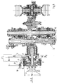
- a friction clutch 1 is part of a motor vehicle that can be installed Drive unit and between an internal combustion engine 2 and a transmission 3rd effective.
- a crankshaft 4 of the internal combustion engine 2 is shown; of the Gear 3, two gearwheels supporting shafts 5 and 6, which are transverse to one Vehicle longitudinal direction A-A run - Fig. 1 -.
- With a disc spring 7 of several Clutch disks 8 and 9 having friction clutch 1 works Disengaging device 10, which has a hydraulic actuating device 11, together.
- the release device 10 comprising a release bearing 12 is included Actuator 11 arranged within a housing 13, the Actuator 11 is provided with a cylinder housing 14 in which a axially movable actuating piston 15 works.
- the cylinder housing 14 of the hydraulic actuating device 11 is with a Support frame 16 connected to an adjacent to the internal combustion engine 2 and the Friction clutch 1 is arranged, regardless of the latter surrounding Housing 13.
- the support frame 16 is on an end face 17 or on a wall 18 of the Internal combustion engine 2 attached, and it has a distance As to the end face 17 or Wall 18 and friction clutch 1 arranged bearing plate 19.
- the bearing plate 19 With the bearing plate 19, the cylinder housing 14 and fastening struts 20, 21 and 22 are connected, which are approximately at right angles away from the mounting plate 19 away struts 20, 21 and 22 encompass an outer diameter Ad of the friction clutch 1 support the wall 18 and with the help of screws 23 on the wall 18 of the Internal combustion engine 2 are held in position.
- the bearing plate 19 has approximately the shape of an equilateral triangle Pages 24, 25 and 26, at the tips 27, 28 and 29 of the fastening struts 20, 21 and 22 are attached.
- the friction clutch 1 surrounding Mounting struts 20, 21 and 22 made in one piece with the bearing plate 19, this also applies analogously to the cylinder housing 14.
- the bearing plate designed in this way 19 is designed as a cast part, it being made of light metal or iron metal Genus can be.
- each fastening strut has e.g. 21 a strut eye 30 with circular cylindrical cross-section, from the tangentially relatively short stiffening flanges 31 and 32 are led away in the direction of pages 21 and 22. additionally can the fastening struts 20, 21 and 22 or the strut eyes 30 with web-like Node struts 33 are supported, which merge into reinforcing ribs 34.
- an inside 35 of the bearing plate 19 with a variety of different ribs provided that the bearing plate 19 a defined strength lend and the cylinder housing 14 holds functionally on the latter.
- connections 36 and 37 and lines 38 and 39 for the hydraulic actuator 11 integrated are in the bearing plate 19 connections 36 and 37 and lines 38 and 39 for the hydraulic actuator 11 integrated.
Landscapes
- Engineering & Computer Science (AREA)
- General Engineering & Computer Science (AREA)
- Mechanical Engineering (AREA)
- Hydraulic Clutches, Magnetic Clutches, Fluid Clutches, And Fluid Joints (AREA)
Abstract
Description
- Fig. 1
- einen Längsschnitt durch eine Reibungskupplung nach der Erfindung,
- Fig. 2
- einen Schnitt nach der Linie II-II der Fig. 1 in größerem Maßstab,
- Fig. 3
- einen Schnitt nach der Linie III-III der Fig. 2,
- Fig. 4
- eine Einzelheit X der Fig. 1 in Schrägansicht.
Claims (10)
- Reibungskupplung für ein Antriebsaggregat eines Kraftfahrzeugs, die zwischen einer Brennkraftmaschine und einem Getriebe wirksam ist und eine Ausrückvorrichtung umfasst, wobei die innerhalb eines Gehäuses angeordnete Ausrückvorrichtung ein Ausrücklager und eine hydraulische Betätigungseinrichtung mit einem Zylindergehäuse und einem in letzterem arbeitenden Betätigungskolben aufweist, dadurch gekennzeichnet, dass das Zylindergehäuse (14) der hydraulischen Betätigungseinrichtung (11) an einem benachbart der Brennkraftmaschine (2) und der Reibungskupplung (1) angeordneten Traggestell (16) angebracht ist, das unabhängig vom Gehäuse (13) ausgebildet ist.
- Reibungskupplung nach Anspruch 1, dadurch gekennzeichnet, dass das Traggestell (16) an einer eine Stirnseite (17) bildenden Wand (18) der Brennkraftmaschine (2) befestigt ist.
- Reibungskupplung nach den Ansprüchen 1 und 2, dadurch gekennzeichnet, dass das Traggestell (16) mit einer zur Wand (18) der Brennkraftmaschine und zur Reibungskupplung mit Abstand (As) angeordneten Lagerplatte (19) versehen ist, an der das Zylindergehäuse (14) der Betätigungseinrichtung (11) angebracht ist.
- Reibungskupplung nach Anspruch 3, dadurch gekennzeichnet, dass die Lagerplatte (19) mit zur Wand (18) hin ausgerichteten einen Außendurchmesser (Ad) der Reibungskupplung (1) umgreifende Befestigungsstreben (20,21,22) versehen ist, die sich an der Wand (18) abstützen und unter Vermittlung von Schrauben (23) an besagter Wand (18) befestigt sind.
- Reibungskupplung nach Anspruch 10, dadurch gekennzeichnet, dass jede Befestigungsstrebe (20,21,22) ein Strebenauge (30) mit kreiszylinderischem Querschnitt aufweist, von dem relativ kurze Versteifungsflansche (31,32) tangential weggeführt sind.
- Reibungskupplung nach den Ansprüchen 3 und 4, dadurch gekennzeichnet, dass die Lagerplatte (19) etwa die Form eines gleichseitigen Dreiecks mit Seiten (24,25,26) besitzt, an dessen Spitzen (27,28,29) die Befestigungsstreben (20,21,22) angebracht sind.
- Reibungskupplung nach einem oder mehreren der vorangehenden Ansprüche, dadurch gekennzeichnet, dass die Befestigungsstreben (20,21,22) aus einem Stück mit der Lagerplatte ( 19) hergestellt sind.
- Reibungskupplung nach einem oder mehreren der vorangehenden Ansprüche, dadurch gekennzeichnet, dass das Zylindergehäuse (14) aus einem Stück mit der Lagerplatte (19) hergestellt ist.
- Reibungskupplung nach den Ansprüchen 7 und 8, dadurch gekennzeichnet, dass die Lagerplatte (19) als Gussteil leichtmetallischer oder eisenmetallischer Gattung ausgebildet ist.
- Reibungskupplung nach den Ansprüchen 1 und 2, dadurch gekennzeichnet, dass in die Lagerplatte (19) Anschlüsse (36,37) und Leitungen (38,39) für die hydraulische Betätigungseinrichtung (11) integriert sind.
Applications Claiming Priority (2)
| Application Number | Priority Date | Filing Date | Title |
|---|---|---|---|
| DE10308771A DE10308771B4 (de) | 2003-02-28 | 2003-02-28 | Reibungskupplung für ein Antriebsaggregat eines Kraftfahrzeugs |
| DE10308771 | 2003-02-28 |
Publications (2)
| Publication Number | Publication Date |
|---|---|
| EP1452761A1 true EP1452761A1 (de) | 2004-09-01 |
| EP1452761B1 EP1452761B1 (de) | 2006-08-09 |
Family
ID=32748115
Family Applications (1)
| Application Number | Title | Priority Date | Filing Date |
|---|---|---|---|
| EP03029501A Expired - Lifetime EP1452761B1 (de) | 2003-02-28 | 2003-12-20 | Reibungskupplung für ein Antriebsaggregat eines Kraftfahrzeugs |
Country Status (4)
| Country | Link |
|---|---|
| US (1) | US7021444B2 (de) |
| EP (1) | EP1452761B1 (de) |
| JP (1) | JP2004263869A (de) |
| DE (2) | DE10308771B4 (de) |
Families Citing this family (1)
| Publication number | Priority date | Publication date | Assignee | Title |
|---|---|---|---|---|
| EP2280183B1 (de) * | 2009-07-27 | 2013-03-27 | ZF Friedrichshafen AG | Gezogene Reibungskupplung mit integriertem Ausrücker |
Citations (3)
| Publication number | Priority date | Publication date | Assignee | Title |
|---|---|---|---|---|
| EP0383576A1 (de) * | 1989-02-15 | 1990-08-22 | Eli M. Ladin | Betätigung einer Kraftfahrzeugkupplung |
| US5183141A (en) * | 1990-05-24 | 1993-02-02 | Kabushiki Kaisha Daikin Seisakusho | Release mechanism for pull-type clutch |
| FR2735726A1 (fr) * | 1995-06-23 | 1996-12-27 | Renault | Dispositif de transmission pour vehicule electrique |
Family Cites Families (15)
| Publication number | Priority date | Publication date | Assignee | Title |
|---|---|---|---|---|
| US4102446A (en) * | 1974-01-22 | 1978-07-25 | Societe Anonyme Francaise Du Ferodo | Hydraulically operated clutch |
| DE3623627C2 (de) * | 1986-07-12 | 1995-02-16 | Fichtel & Sachs Ag | Verfahren zum Betrieb einer Reibungskupplung |
| US4848549A (en) * | 1988-04-08 | 1989-07-18 | Chipper Industries, Inc. | Coaxial adjustable hydraulic clutch actuator |
| EP0433466B1 (de) * | 1989-07-04 | 1994-12-14 | Kabushiki Kaisha Kubota | Betätigungsvorrichtung für kraftwagenkupplung |
| US5133439A (en) * | 1991-02-01 | 1992-07-28 | Rms Engineering, Inc. | Fluid pressure actuated actuator mechanism for clutches and the like |
| AU637280B2 (en) * | 1991-03-25 | 1993-05-20 | Kubota Corporation | Hydraulic clutch operating apparatus |
| FR2712948B1 (fr) * | 1993-09-29 | 1996-01-05 | Valeo | Dispositif d'embrayage de véhicule automobile du type tiré et à actionnement hydraulique. |
| FR2738886B1 (fr) * | 1995-09-14 | 1997-10-24 | Valeo | Dispositif de debrayage a commande hydraulique pour embrayage, notamment pour vehicules automobiles |
| DE19604159C2 (de) * | 1996-02-06 | 1998-04-09 | Freudenberg Carl Fa | Kupplungsbetätigungseinrichtung |
| US5823308A (en) * | 1996-02-16 | 1998-10-20 | Ladin; Eli M. | Clutch control with multiple actuating cylinders for a pull-type clutch |
| US5752591A (en) * | 1996-03-26 | 1998-05-19 | Meritor Heavy Vehicle Systems, Llc | Plug-in hydraulic cylinder housing for hydraulically actuated clutch |
| US5722520A (en) * | 1996-03-26 | 1998-03-03 | Meritor Heavy Vehicle Systems, Llc | Reaction surfaces for hydraulically actuated clutches |
| FR2753772B1 (fr) * | 1996-09-26 | 1998-12-18 | Connecteur hydraulique pour commande hydraulique d'embrayage | |
| DE19742468A1 (de) * | 1997-09-26 | 1999-04-01 | Schaeffler Waelzlager Ohg | Nehmerzylindergehäuse aus Kunststoff, in das eine Führungshülse aus Stahl eingesetzt ist |
| DE10039242A1 (de) * | 1999-08-24 | 2001-03-08 | Luk Lamellen & Kupplungsbau | Ausrücksystem |
-
2003
- 2003-02-28 DE DE10308771A patent/DE10308771B4/de not_active Expired - Fee Related
- 2003-12-20 EP EP03029501A patent/EP1452761B1/de not_active Expired - Lifetime
- 2003-12-20 DE DE50304567T patent/DE50304567D1/de not_active Expired - Lifetime
-
2004
- 2004-02-24 JP JP2004048493A patent/JP2004263869A/ja not_active Withdrawn
- 2004-03-01 US US10/789,447 patent/US7021444B2/en not_active Expired - Lifetime
Patent Citations (3)
| Publication number | Priority date | Publication date | Assignee | Title |
|---|---|---|---|---|
| EP0383576A1 (de) * | 1989-02-15 | 1990-08-22 | Eli M. Ladin | Betätigung einer Kraftfahrzeugkupplung |
| US5183141A (en) * | 1990-05-24 | 1993-02-02 | Kabushiki Kaisha Daikin Seisakusho | Release mechanism for pull-type clutch |
| FR2735726A1 (fr) * | 1995-06-23 | 1996-12-27 | Renault | Dispositif de transmission pour vehicule electrique |
Also Published As
| Publication number | Publication date |
|---|---|
| JP2004263869A (ja) | 2004-09-24 |
| DE50304567D1 (de) | 2006-09-21 |
| US20040251108A1 (en) | 2004-12-16 |
| US7021444B2 (en) | 2006-04-04 |
| DE10308771A1 (de) | 2004-09-16 |
| DE10308771B4 (de) | 2005-07-14 |
| EP1452761B1 (de) | 2006-08-09 |
Similar Documents
| Publication | Publication Date | Title |
|---|---|---|
| DE102006028552B4 (de) | Kupplungseinrichtung mit Kupplungsscheibe | |
| EP0412541B1 (de) | Teilbelag-Scheibenbremse | |
| DE102008017139B4 (de) | Zwillingskupplungsvorrichtung | |
| DE3033140C2 (de) | Elektromagnetische Zweistufenkupplung | |
| DE10313351A1 (de) | Stellglied | |
| DE102004062731A1 (de) | Scheibenbremse mit Federanordung | |
| DE4120128B4 (de) | Betätigungsvorrichtung, insbesondere für die Steuerung einer Kraftfahrzeugkupplung | |
| DE4235519A1 (de) | Schwungradausbildung | |
| DE4303371B4 (de) | Drehschwingungsdämpfer, insbesondere Doppel-Dämpfungsrad und Kupplungsscheibe für Kraftfahrzeuge | |
| DE112013000105T5 (de) | Drehvorrichtung für ein Arbeitsfahrzeug | |
| DE112008000113B4 (de) | Kupplungsbetätigungsvorrichtung mit einer Anordnung zur Unterdrückung von Eigen-Resonanzen | |
| DE102012216116B4 (de) | Riemenscheibenentkoppler | |
| DE102010028841A1 (de) | Dämpfventileinrichtung mit einer mehrstufigen Dämpfkraftkennlinie | |
| EP1347192A2 (de) | Drehsteife aber radial nachgiebige Kupplung | |
| DE1957991U (de) | Zweistufiges zahnrad-untersetzungsgetriebe. | |
| EP1452761B1 (de) | Reibungskupplung für ein Antriebsaggregat eines Kraftfahrzeugs | |
| DE10047242C1 (de) | Anlasserrad für ein Kraftfahrzeug oder dgl. | |
| DE102010033070A1 (de) | Zwischenwand und Kraftfahrzeuggetriebe | |
| DE102019134521A1 (de) | Vorrichtung und Verfahren zum Betätigen einer Parksperre | |
| EP0057354A2 (de) | Reibungskupplung für Kraftfahrzeuge | |
| DE102017005244A1 (de) | Drehmomentübertragungsvorrichtung und Antriebsstrang mit einer solchen Drehmomentübertragungsvorrichtung | |
| DE60005286T2 (de) | Antriebsvorrichtung einer Antriebswelle eines Schaltgetriebes für Hybridfahrzeuge | |
| DE102005014303B4 (de) | Rastiereinhiet für ein Schaltwelle | |
| DE102016202035B3 (de) | Betätigungszylinder mit an ihm befestigten Faltenbalg | |
| EP1452380B1 (de) | Antriebsaggregat für ein Kraftfahrzeug |
Legal Events
| Date | Code | Title | Description |
|---|---|---|---|
| PUAI | Public reference made under article 153(3) epc to a published international application that has entered the european phase |
Free format text: ORIGINAL CODE: 0009012 |
|
| AK | Designated contracting states |
Kind code of ref document: A1 Designated state(s): AT BE BG CH CY CZ DE DK EE ES FI FR GB GR HU IE IT LI LU MC NL PT RO SE SI SK TR |
|
| AX | Request for extension of the european patent |
Extension state: AL LT LV MK |
|
| 17P | Request for examination filed |
Effective date: 20050301 |
|
| AKX | Designation fees paid |
Designated state(s): DE FR GB IT |
|
| RBV | Designated contracting states (corrected) |
Designated state(s): DE FR GB IT |
|
| GRAP | Despatch of communication of intention to grant a patent |
Free format text: ORIGINAL CODE: EPIDOSNIGR1 |
|
| GRAS | Grant fee paid |
Free format text: ORIGINAL CODE: EPIDOSNIGR3 |
|
| GRAA | (expected) grant |
Free format text: ORIGINAL CODE: 0009210 |
|
| AK | Designated contracting states |
Kind code of ref document: B1 Designated state(s): DE FR GB IT |
|
| REG | Reference to a national code |
Ref country code: GB Ref legal event code: FG4D Free format text: NOT ENGLISH |
|
| REF | Corresponds to: |
Ref document number: 50304567 Country of ref document: DE Date of ref document: 20060921 Kind code of ref document: P |
|
| GBT | Gb: translation of ep patent filed (gb section 77(6)(a)/1977) |
Effective date: 20061113 |
|
| ET | Fr: translation filed | ||
| PLBE | No opposition filed within time limit |
Free format text: ORIGINAL CODE: 0009261 |
|
| STAA | Information on the status of an ep patent application or granted ep patent |
Free format text: STATUS: NO OPPOSITION FILED WITHIN TIME LIMIT |
|
| 26N | No opposition filed |
Effective date: 20070510 |
|
| REG | Reference to a national code |
Ref country code: FR Ref legal event code: TP |
|
| REG | Reference to a national code |
Ref country code: FR Ref legal event code: CD |
|
| PGFP | Annual fee paid to national office [announced via postgrant information from national office to epo] |
Ref country code: FR Payment date: 20110104 Year of fee payment: 8 |
|
| REG | Reference to a national code |
Ref country code: FR Ref legal event code: TP |
|
| PGFP | Annual fee paid to national office [announced via postgrant information from national office to epo] |
Ref country code: GB Payment date: 20101221 Year of fee payment: 8 |
|
| REG | Reference to a national code |
Ref country code: GB Ref legal event code: 732E Free format text: REGISTERED BETWEEN 20110310 AND 20110316 |
|
| REG | Reference to a national code |
Ref country code: GB Ref legal event code: 732E Free format text: REGISTERED BETWEEN 20110331 AND 20110406 |
|
| PGFP | Annual fee paid to national office [announced via postgrant information from national office to epo] |
Ref country code: IT Payment date: 20101223 Year of fee payment: 8 Ref country code: DE Payment date: 20101115 Year of fee payment: 8 |
|
| GBPC | Gb: european patent ceased through non-payment of renewal fee |
Effective date: 20111220 |
|
| REG | Reference to a national code |
Ref country code: FR Ref legal event code: ST Effective date: 20120831 |
|
| REG | Reference to a national code |
Ref country code: DE Ref legal event code: R119 Ref document number: 50304567 Country of ref document: DE Effective date: 20120703 |
|
| PG25 | Lapsed in a contracting state [announced via postgrant information from national office to epo] |
Ref country code: GB Free format text: LAPSE BECAUSE OF NON-PAYMENT OF DUE FEES Effective date: 20111220 Ref country code: DE Free format text: LAPSE BECAUSE OF NON-PAYMENT OF DUE FEES Effective date: 20120703 |
|
| PG25 | Lapsed in a contracting state [announced via postgrant information from national office to epo] |
Ref country code: IT Free format text: LAPSE BECAUSE OF NON-PAYMENT OF DUE FEES Effective date: 20111220 |
|
| PG25 | Lapsed in a contracting state [announced via postgrant information from national office to epo] |
Ref country code: FR Free format text: LAPSE BECAUSE OF NON-PAYMENT OF DUE FEES Effective date: 20120102 |