EP1452391A2 - Connexion électrique pour équipement extérieur de véhicule - Google Patents
Connexion électrique pour équipement extérieur de véhicule Download PDFInfo
- Publication number
- EP1452391A2 EP1452391A2 EP03027413A EP03027413A EP1452391A2 EP 1452391 A2 EP1452391 A2 EP 1452391A2 EP 03027413 A EP03027413 A EP 03027413A EP 03027413 A EP03027413 A EP 03027413A EP 1452391 A2 EP1452391 A2 EP 1452391A2
- Authority
- EP
- European Patent Office
- Prior art keywords
- bolt
- circuit
- exterior component
- vehicle exterior
- mirror
- Prior art date
- Legal status (The legal status is an assumption and is not a legal conclusion. Google has not performed a legal analysis and makes no representation as to the accuracy of the status listed.)
- Withdrawn
Links
Images


Classifications
-
- B—PERFORMING OPERATIONS; TRANSPORTING
- B60—VEHICLES IN GENERAL
- B60Q—ARRANGEMENT OF SIGNALLING OR LIGHTING DEVICES, THE MOUNTING OR SUPPORTING THEREOF OR CIRCUITS THEREFOR, FOR VEHICLES IN GENERAL
- B60Q1/00—Arrangement of optical signalling or lighting devices, the mounting or supporting thereof or circuits therefor
- B60Q1/26—Arrangement of optical signalling or lighting devices, the mounting or supporting thereof or circuits therefor the devices being primarily intended to indicate the vehicle, or parts thereof, or to give signals, to other traffic
- B60Q1/2661—Arrangement of optical signalling or lighting devices, the mounting or supporting thereof or circuits therefor the devices being primarily intended to indicate the vehicle, or parts thereof, or to give signals, to other traffic mounted on parts having other functions
- B60Q1/2665—Arrangement of optical signalling or lighting devices, the mounting or supporting thereof or circuits therefor the devices being primarily intended to indicate the vehicle, or parts thereof, or to give signals, to other traffic mounted on parts having other functions on rear-view mirrors
-
- B—PERFORMING OPERATIONS; TRANSPORTING
- B60—VEHICLES IN GENERAL
- B60Q—ARRANGEMENT OF SIGNALLING OR LIGHTING DEVICES, THE MOUNTING OR SUPPORTING THEREOF OR CIRCUITS THEREFOR, FOR VEHICLES IN GENERAL
- B60Q1/00—Arrangement of optical signalling or lighting devices, the mounting or supporting thereof or circuits therefor
- B60Q1/26—Arrangement of optical signalling or lighting devices, the mounting or supporting thereof or circuits therefor the devices being primarily intended to indicate the vehicle, or parts thereof, or to give signals, to other traffic
- B60Q1/30—Arrangement of optical signalling or lighting devices, the mounting or supporting thereof or circuits therefor the devices being primarily intended to indicate the vehicle, or parts thereof, or to give signals, to other traffic for indicating rear of vehicle, e.g. by means of reflecting surfaces
- B60Q1/302—Arrangement of optical signalling or lighting devices, the mounting or supporting thereof or circuits therefor the devices being primarily intended to indicate the vehicle, or parts thereof, or to give signals, to other traffic for indicating rear of vehicle, e.g. by means of reflecting surfaces mounted in the vicinity, e.g. in the middle, of a rear window
-
- B—PERFORMING OPERATIONS; TRANSPORTING
- B60—VEHICLES IN GENERAL
- B60R—VEHICLES, VEHICLE FITTINGS, OR VEHICLE PARTS, NOT OTHERWISE PROVIDED FOR
- B60R1/00—Optical viewing arrangements; Real-time viewing arrangements for drivers or passengers using optical image capturing systems, e.g. cameras or video systems specially adapted for use in or on vehicles
- B60R1/02—Rear-view mirror arrangements
- B60R1/06—Rear-view mirror arrangements mounted on vehicle exterior
- B60R1/062—Rear-view mirror arrangements mounted on vehicle exterior with remote control for adjusting position
- B60R1/07—Rear-view mirror arrangements mounted on vehicle exterior with remote control for adjusting position by electrically powered actuators
Definitions
- This invention relates to a wiring arrangement for a vehicle exterior component including an electric part.
- the electrically operated retractable door mirror incorporates a motor circuit for adjusting a mirror angle, a motor circuit for retracting and deploying a mirror body, and the like.
- the door mirror is fixed on an outer surface of the vehicle body with two or three of bolt-nut pairs, while the motor circuit or the like incorporated in the door mirror is connected via a wiring harness. to a feeder circuit, a switch circuit or the like equipped in the vehicle body.
- the door mirror has been becoming multi-functional by incorporating a variety of electric parts and electric circuits such as a turn signal lamp, a foot light, a microphone, a speaker, and an antenna circuit, thus tends to have an increased number of wires in the wiring harness for connecting to the circuits in the vehicle body.
- This technique uses a signal converter circuit provided in the vehicle body to convert the operating signals of various kinds into signals each having a unique frequency which are in turn transmitted over a single wire into the door mirror in which the signals are restored by a reverse signal converter circuit and transmitted to the electric parts of various kinds.
- the present invention has been made to address the above-described disadvantages, and provides a wiring arrangement for a vehicle exterior component (e.g., a door mirror) which can prevent a defect in electric connectivity to an electric part incorporated in the vehicle exterior component, and which can reduce the number of assembly steps (i.e., man-hours for assembly) of the vehicle exterior component.
- a vehicle exterior component e.g., a door mirror
- the at least two bolt-nut pairs may preferably include a first bolt-nut pair and a second bolt-nut pair, such that the electric part is connected via the first bolt-nut pair to one of an ACC terminal and an IG terminal of an ignition switch circuit in the vehicle body, and via the second bolt-nut pair to a GND terminal of the ignition switch circuit.
- the electric part is supplied with power and actuated when the ignition switch is turned to an "ACC" position or "IG" position.
- the signal converter circuit and the reverse signal converter circuit may preferably be connected via one of the above first bolt-nut pair and another (third) bolt-nut pair.
- the electric part supplied with power when the ignition switch is turned to an "ACC" position or "IG” position is actuated in accordance with an operating signal received via the third bolt-nut pair.
- a mount for fixing the vehicle exterior component to the vehicle body may be made of an insulating material, and surfaces of the bolt-nut pairs other than a portion for establishing electrical connection may be made electrically insulated.
- the above-described wiring arrangement for a vehicle exterior component according to the present invention may be applied to a door mirror in which a motor-driven circuit including at least one of a mirror angle adjustment circuit and a mirror retracting/deploying operation circuit is incorporated, and to a rear spoiler in which a high mount stop lamp is incorporated.
- the present invention as described above may be embodied in any other vehicle exterior components including one or more of electric parts and fixed to the vehicle body by two or more bolt-nut pairs.
- FIGs. 1 through 3 A detailed description will be given of one exemplified embodiment of a wiring arrangement for a vehicle exterior component according to the present invention with reference to FIGs. 1 through 3.
- the wiring arrangement for a vehicle exterior component is applied to a door mirror 5 fixed onto an outer surface of a vehicle body 4 by three bolt-nut pairs: a first bolt-nut pair 1, a second bolt-nut pair 2 and a third bolt-nut pair 3.
- the door mirror 5 includes a mirror base 5A, a mirror body 5B, and a reflector 5C.
- the mirror base 5A is fixed to a mount 4A provided in the vehicle body 4 by the three bolt-nut pairs 1-3.
- the mirror body 5B is swingably supported on the mirror base 5A so that the mirror body 5B can swing between an operative position where the mirror body 5A protrudes from the vehicle body 4 to an outside thereof, and a retracted position where the mirror body 5A folds flat along the outer surface of the vehicle body 4.
- the reflector 5C is fitted in the mirror body 5A in a manner that permits an angle thereof to be adjusted appropriately.
- the mount 4A in the vehicle body 4 is formed of electrically insulating plastic.
- the mount 4A are formed (e.g., inserted) three nuts 1A-3A constituting the mates to three bolts 1B-3A of the bolt-nut pairs 1-3 and wiring for connecting the nuts 1A-3A to a signal converter circuit 6.
- the signal converter circuit 6 may be fitted in the mount 4A or installed in other locations of the vehicle body 4.
- the mirror base 5A and the mirror body 5B of the door mirror 5 as well are formed of electrically insulating plastic.
- the mirror base 5A are formed (e.g., inserted) three bolts 1B-3B constituting the counterparts of the nuts 1A-3A of the bolt-nut pairs 1-3, and wiring for connecting the bolts 1B-3B to a reverse signal converter circuit 7.
- the reverse signal converter circuit 7 may be fitted in the mirror base 5A or installed in other locations of the door mirror 5.
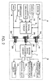
- an ACC (IG) terminal 8 of an ignition switch circuit is connected to the nut 1A and a positive terminal of the signal converter circuit 6 in the mount 4A, while a negative terminal of the signal converter circuit 6 and the nut 2A are connected to a GND terminal 9 of the ignition switch circuit.
- Input terminals of the signal converter circuit 6 are each connected respectively to output terminals of a mirror switch 10, a turn signal switch 11 and a mirror heater switch 12 each provided in an instrument panel (not shown).
- An output terminal of the signal converter circuit 6 is connected to the nut 3A.
- the bolt 1B is connected to a positive terminal of the reverse signal converter circuit 7 in the mirror base 5A, while a negative terminal of the reverse signal converter circuit 7 is connected to the bolt 2B.
- Output terminals of the reverse signal converter 7 are each connected respectively to a mirror angle adjustment circuit 13, a mirror retracting/deploying operation circuit 14, a turn signal circuit 15 and a mirror heater circuit 16 each provided in the mirror body 5B.
- the mirror switch 10 is a switch for transmitting a predetermined operating signal generated in accordance with a manual operation to the mirror angle adjustment circuit 13 and the mirror retracting/deploying operation circuit 14.
- the mirror angle adjustment circuit 13 controls a motor for adjustment (not shown) incorporated in the mirror body 5B to adjust the angle of the reflector 5C upward, downward, rightward and leftward.
- the mirror retracting/deploying operation circuit 14 controls a motor for retracting/deploying operation (not shown) incorporated in the mirror body 5B to swing the mirror body 5B to the operative position or to the retracted position.
- the turn signal switch 11 is a switch for transmitting a predetermined operating signal generated in accordance with an operation of a blinker to the turn signal circuit 15.
- the turn signal circuit 15 that has received the operating signal from the turn signal switch 11 actuates a blinker (not shown) attached to the mirror body 5B to flash on and off.
- the mirror heater switch 12 is a switch for transmitting a predetermined operating signal generated in accordance with a manual operation to the mirror heater circuit 16.
- the mirror heater circuit 16 activates a mirror heater (not shown) incorporated in the mirror body 5B to heat the reflector 5C so as to remove raindrops, dew, frost, accreting ice, etc. forming on the reflector 5C.
- the signal converter circuit 6 converts the predetermined operating signals transmitted from the mirror switch 10, the turn signal switch 11 and the mirror heater switch 12 into an analog signal as a combination of predetermined unique frequencies, and outputs the analog signal via the nut 3A and the bolt 3B of the third bolt-nut pair 3 to the reverse signal converter circuit 7 for a predetermined period of time.
- the analog signal is, for example, a dual tone multiple frequency (DTMF) signal.
- the reverse signal converter circuit 7 receives the DTMF analog signal transmitted from the signal converter circuit 6 for a predetermined period of time, and reversely converts the DTMF analog signal into the predetermined operating signals having frequency components derived from the mirror switch 10, the turn signal switch 11 and the mirror heater switch 12.
- the predetermined operating signals restored (reversely converted) by the reverse signal converter circuit 7 are transmitted to the mirror angle adjustment circuit 13, the mirror retracting/deploying operation circuit 14, the turn signal circuit 15 and the mirror heater circuit 16, respectively.
- all the surfaces of the nuts 1A-3A other than portions for establishing electrical connection e.g ., portions to which wires are soldered
- are electrically insulated e.g. , coated with insulator.
- the bolts 1B-3B are inserted in the mirror base 5A, and thus the surfaces thereof other than a portion for establishing electrical connection ( e.g. , portions to which wires are soldered) are made electrically insulated.
- FIG. 1 illustrates only the right door mirror 5 fixed onto the right side of the vehicle body 4, it is understood that a left door mirror similar to the right door mirror 5 is fixed onto the left side of the vehicle body by three (first, second and third) bolt-nut pairs in a like manner.
- the mirror body 5B of the door mirror 5 is fixed to the mount 4A of the vehicle body 4 by the first bolt-nut pair 1, the second bolt-nut pair 2, and the third bolt-put pair 3, as shown in FIGs. 1 and 2.
- the ACC (IG) terminal 8 of the ignition switch in the vehicle body 4 is connected via the first bolt-nut pair 1 to the positive terminal of the reverse signal converter circuit 7 in the mirror body 5B
- the GND terminal 9 in the vehicle body 4 is connected via the second bolt-nut pair 2 to the negative terminal of the reverse signal converter circuit 7 in the mirror body 5B
- the output terminal of the signal converter circuit 6 in the mount 4A is connected via the third bolt-nut pair 3 to the input terminal of the reverse signal converter circuit 7 in the mirror body 5B.
- the reverse signal converter circuit 7, the mirror angle adjustment circuit 13, the mirror retracting/deploying operation circuit 14, the turn signal circuit 15, the mirror heater circuit 16 and other circuits (not shown) in the door mirror 5 are securely supplied with power and actuated without fail.
- the conventional wiring arrangement using a multi-cable wiring harness could possibly allow the wiring harness to be pinched between the door mirror and the vehicle body upon installation of the door mirror, causing a defect in electric connectivity such as a break or short circuit in the wiring harness, and would involve cumbersome wiring tasks for the wiring harness, which would increase the number of assembly steps (i.e., man-hours for assembly) of the door mirror, thus raising the assembly cost.
- the wiring arrangement according to the present embodiment can prevent such a defect in electric connectivity (e.g. , a break and short circuit), and can reduce the number of assembly steps or man-hours for assembly of the door mirror 5.
- the present invention is not limited to the above-described embodiments, and the wiring arrangement for a vehicle exterior component according to the present invention can be modified as appropriate and embodied with variations.
- the output terminal of the signal converter circuit 6 in the vehicle body 4 may be connected to the nut 1A while the input terminal of the reverse signal converter circuit 7 in the door mirror 5 may also be used as the positive terminal thereof.
- the analog signal converted by the signal converter circuit 6 is transmitted via the nut 1A and the bolt 1B to the input terminal commonly used as the positive terminal, as indicated by a chain double-dashed arrow in FIG. 3.
- the wiring arrangement for a vehicle exterior component according to the present invention can be applied to a rear spoiler 17 in which a high mount stop lamp 17A is incorporated as an electric part, as shown in FIG. 4.
- the rear spoiler 17 is mounted on a trunk lid 4B at a rear of the vehicle body 4, with one leg portion 17B being fixed by the first bolt-nut pair 1 and the second bolt-nut pair 2, and the other leg portion 17C being fixed by the other two bolt-nut pairs.
- the rear spoiler 17 is formed of electrically insulating plastic, and two bolts 1B and 2B constituting the mates to two nuts 1A, 2A of the first and second bolt-nut pairs 1, 2 and a reverse signal converter circuit 7 like the reverse signal converter circuit 7 as shown in FIGs. 1 and 2 are inserted together with a wire for establishing connection therebetween in the leg portion 17B.
- two nuts 1A and 2A constituting the counterparts to the bolts 1B, 2B of the first and second bolt-nut pairs 1, 2 are provided in the trunk lid 4B of the vehicle body 4, and the two nuts 1A and 2A are connected to a signal converter circuit 6 like the signal converter circuit 7 as shown in FIGs. 1 and 2.
- an ACC (IG) terminal 8 of the ignition switch circuit is connected to the nut 1A in the trunk lid 4B, and to a positive terminal of the signal converter circuit 6, while a negative terminal of the signal converter circuit 6 and the nut 2A are connected to a GND terminal 9 of the ignition switch circuit.
- an output terminal of a brake switch 18 installed in a driver's seat (not shown), and an output terminal of the signal converter circuit 6 is connected to the nut 1A.
- the bolt 1B is connected to a positive terminal commonly used as an input terminal of the reverse signal converter circuit 7 providedin the leg portion 17B, and a negative terminal of the reverse signal converter circuit 7 is connected to the bolt 2B.
- Output terminals of the reverse signal converter circuit 7 are connected to the high mount stop lamp 17A incorporated in the rear spoiler 17.
- the leg portions 17B, 17C of the rear spoiler 17 are fixed onto the trunk lid 4B by the first bolt-nut pair 1, the second bolt-nut pair 2, and two other bolt-nut pairs.
- the ACC (IG) terminal 8 of the ignition switch in the vehicle body 4 is connected via the first bolt-nut pair 1 to the positive terminal of the reverse signal converter circuit 7 in the leg portion 17B of the rear spoiler 17.
- the GND terminal 9 in the vehicle body 4 is connected via the second bolt-nut pair 2 to the negative terminal of the reverse signal converter circuit 7 in the leg portion 17B.
- the output terminal of the signal converter circuit 6-in the vehicle body 4 is connected via the bolt-nut pair 1 to the positive terminal commonly used as the input terminal of the reverse signal converter circuit 7 in the leg portion 17B. Therefore, when the ignition switch is turned to the ACC position or the IG position, the reverse signal converter circuit 7 and the high mount stop lamp 17A in the rear spoiler 17 are securely supplied with power and actuated without fail. Thus, the high mount stop lamp 17A can be lit up in response to the operating signal from the brake switch 18 without fail.
- the wiring arrangement for the rear spoiler 17 can prevent a defect in electric connectivity such as a break or short circuit, and can reduce the number of assembly steps or man-hours for assembly of the rear spoiler 17.
- the three (first, second and third) bolt-nut pairs 1-3 may be constructed such that the bolts 1B-3B are inserted in the mount 4A, and the nuts 1A-3A are screwed and fitted from a mirror base 5A side.
- the electric part when the electric part is connected via the first bolt-nut pair to an ACC terminal or an IG terminal of an ignition switch circuit in the vehicle body, and via the second bolt-nut pair to a GND terminal of the ignition switch circuit, the electric part is supplied with power and actuated when the ignition switch is turned to an "ACC" position or "IG" position.
- the signal converter circuit and the reverse signal converter circuit can be connected via the first bolt-nut pair or another (third) bolt-nut pair.
- the electric part supplied with power when the ignition switch is turned to an "ACC" position or "IG” position can be actuated in accordance with an operating signal received via the third bolt-nut pair.
Landscapes
- Engineering & Computer Science (AREA)
- Mechanical Engineering (AREA)
- Multimedia (AREA)
- Rear-View Mirror Devices That Are Mounted On The Exterior Of The Vehicle (AREA)
- Lighting Device Outwards From Vehicle And Optical Signal (AREA)
Applications Claiming Priority (2)
| Application Number | Priority Date | Filing Date | Title |
|---|---|---|---|
| JP2003052461 | 2003-02-28 | ||
| JP2003052461A JP2004262276A (ja) | 2003-02-28 | 2003-02-28 | 車体外装品の配線構造 |
Publications (2)
| Publication Number | Publication Date |
|---|---|
| EP1452391A2 true EP1452391A2 (fr) | 2004-09-01 |
| EP1452391A3 EP1452391A3 (fr) | 2004-09-15 |
Family
ID=32767822
Family Applications (1)
| Application Number | Title | Priority Date | Filing Date |
|---|---|---|---|
| EP03027413A Withdrawn EP1452391A3 (fr) | 2003-02-28 | 2003-11-27 | Connexion électrique pour équipement extérieur de véhicule |
Country Status (3)
| Country | Link |
|---|---|
| US (1) | US6910909B2 (fr) |
| EP (1) | EP1452391A3 (fr) |
| JP (1) | JP2004262276A (fr) |
Families Citing this family (5)
| Publication number | Priority date | Publication date | Assignee | Title |
|---|---|---|---|---|
| US7621588B2 (en) * | 2006-01-10 | 2009-11-24 | Chrysler Group Llc | Deployable deflector for outside mirror |
| JP4677395B2 (ja) * | 2006-11-17 | 2011-04-27 | 株式会社村上開明堂 | 配線構造 |
| DE102016110845A1 (de) * | 2016-06-14 | 2017-12-14 | Dr. Ing. H.C. F. Porsche Aktiengesellschaft | Aerodynamikbauteil für ein Fahrzeug |
| WO2020064798A1 (fr) | 2018-09-26 | 2020-04-02 | Zf Friedrichshafen Ag | Dispositif pour détecter un environnement de véhicule pour un véhicule |
| KR102715798B1 (ko) * | 2019-07-01 | 2024-10-14 | (주)엘엑스하우시스 | 웰컴 라이팅 플라스틱 루프랙 |
Family Cites Families (12)
| Publication number | Priority date | Publication date | Assignee | Title |
|---|---|---|---|---|
| US2312300A (en) | 1940-09-20 | 1943-02-23 | Colleen M Baerwald | Stop light for vehicles and trailers |
| GB1040852A (en) | 1963-10-29 | 1966-09-01 | Talbot Yorck | Improvements in or relating to rear vision mirror assemblies for vehicles |
| US3737849A (en) * | 1971-08-30 | 1973-06-05 | P Mead | Seat belt alarm system |
| DE3606004A1 (de) | 1986-02-25 | 1987-08-27 | Ernst Rieger | Vorrichtung zum haltern von rundumkennleuchten an kraftfahrzeugen |
| DE4026945C2 (de) | 1990-08-25 | 1993-12-09 | Porsche Ag | Heckleuchte für ein Kraftfahrzeug |
| JPH04328043A (ja) | 1991-04-26 | 1992-11-17 | Nippon Sheet Glass Co Ltd | 車輌用標識灯の取付構造 |
| JPH078086A (ja) | 1993-06-29 | 1995-01-13 | Kubota Corp | 刈取収穫機の刈取部 |
| US5791936A (en) * | 1996-06-20 | 1998-08-11 | Yazaki Corporation | Protective cover for ground junction connector |
| US6426619B1 (en) * | 1998-12-09 | 2002-07-30 | Cts Corporation | Pedal with integrated position sensor |
| JP4003363B2 (ja) * | 1999-12-24 | 2007-11-07 | 株式会社デンソー | 燃焼圧センサ構造体 |
| US6357101B1 (en) * | 2000-03-09 | 2002-03-19 | The Boeing Company | Method for installing fasteners in a workpiece |
| US6784803B1 (en) * | 2001-08-23 | 2004-08-31 | Seatbelt Safety First--Llc | Apparatus and methods for monitoring and detecting seat belt usage |
-
2003
- 2003-02-28 JP JP2003052461A patent/JP2004262276A/ja active Pending
- 2003-11-26 US US10/721,546 patent/US6910909B2/en not_active Expired - Fee Related
- 2003-11-27 EP EP03027413A patent/EP1452391A3/fr not_active Withdrawn
Also Published As
| Publication number | Publication date |
|---|---|
| EP1452391A3 (fr) | 2004-09-15 |
| JP2004262276A (ja) | 2004-09-24 |
| US6910909B2 (en) | 2005-06-28 |
| US20040171281A1 (en) | 2004-09-02 |
Similar Documents
| Publication | Publication Date | Title |
|---|---|---|
| JP3515402B2 (ja) | 電源ネットワーク装置 | |
| US6127919A (en) | Rearview vehicle mirror with audio speakers | |
| US6312135B1 (en) | Electric external rear view mirror | |
| US7246840B2 (en) | Vehicle liftgate window component module | |
| JPH02124341A (ja) | 自動車の後進警告装置 | |
| US6910909B2 (en) | Wiring arrangement for vehicle exterior component | |
| US20040124664A1 (en) | Vehicle liftgate with accessory component module | |
| US6565142B1 (en) | Vehicle door inner trim panel assembly including electrical control panel | |
| EP1180815A3 (fr) | Structure de connexion de fils électriques d'une unité de lampe | |
| EP0857618A3 (fr) | Dispositif de montage d'une unité de commande de moteur de véhicule | |
| WO2003045733A1 (fr) | Appareil de commande d'utilisation diurne des lampes d'une automobile | |
| JP3449512B2 (ja) | バックアップ装置 | |
| JPH0522207U (ja) | 自動車用スイツチパネル装置 | |
| CN223949068U (zh) | 一种无线输电与控制的汽车后视镜 | |
| JP2604512Y2 (ja) | カプラ装着部材 | |
| JPH10144199A (ja) | 車両用ヒューズ装置 | |
| KR100507091B1 (ko) | 차량의 지능형 네트워크에서 멀티 펑션 스위치 신호통신모듈 | |
| JPH09118182A (ja) | 自動車における電装品制御装置 | |
| WO2003069735A3 (fr) | Dispositif presentant une unite equipee d'un raccord electrique | |
| JPH10270128A (ja) | ウインドの電気端子コネクタ | |
| JP2589375Y2 (ja) | 自動車のランプ用ハーネス装置 | |
| JP2589075Y2 (ja) | ワイヤハーネスの取り出し構造 | |
| JPH08337118A (ja) | 車両用サンバイザの電気配線構造 | |
| JP2004098941A (ja) | バニティランプの回路構成 | |
| JPH0115212Y2 (fr) |
Legal Events
| Date | Code | Title | Description |
|---|---|---|---|
| PUAI | Public reference made under article 153(3) epc to a published international application that has entered the european phase |
Free format text: ORIGINAL CODE: 0009012 |
|
| PUAL | Search report despatched |
Free format text: ORIGINAL CODE: 0009013 |
|
| AK | Designated contracting states |
Kind code of ref document: A2 Designated state(s): AT BE BG CH CY CZ DE DK EE ES FI FR GB GR HU IE IT LI LU MC NL PT RO SE SI SK TR |
|
| AX | Request for extension of the european patent |
Extension state: AL LT LV MK |
|
| AK | Designated contracting states |
Kind code of ref document: A3 Designated state(s): AT BE BG CH CY CZ DE DK EE ES FI FR GB GR HU IE IT LI LU MC NL PT RO SE SI SK TR |
|
| AX | Request for extension of the european patent |
Extension state: AL LT LV MK |
|
| 17P | Request for examination filed |
Effective date: 20041025 |
|
| AKX | Designation fees paid |
Designated state(s): DE FR GB IT |
|
| STAA | Information on the status of an ep patent application or granted ep patent |
Free format text: STATUS: THE APPLICATION HAS BEEN WITHDRAWN |
|
| 18W | Application withdrawn |
Effective date: 20050817 |