EP1452341A2 - Lenkrolle und Halterung dafür - Google Patents
Lenkrolle und Halterung dafür Download PDFInfo
- Publication number
- EP1452341A2 EP1452341A2 EP04250987A EP04250987A EP1452341A2 EP 1452341 A2 EP1452341 A2 EP 1452341A2 EP 04250987 A EP04250987 A EP 04250987A EP 04250987 A EP04250987 A EP 04250987A EP 1452341 A2 EP1452341 A2 EP 1452341A2
- Authority
- EP
- European Patent Office
- Prior art keywords
- castor
- mounting bracket
- shaft
- bed
- socket
- Prior art date
- Legal status (The legal status is an assumption and is not a legal conclusion. Google has not performed a legal analysis and makes no representation as to the accuracy of the status listed.)
- Withdrawn
Links
Images


Classifications
-
- B—PERFORMING OPERATIONS; TRANSPORTING
- B60—VEHICLES IN GENERAL
- B60B—VEHICLE WHEELS; CASTORS; AXLES FOR WHEELS OR CASTORS; INCREASING WHEEL ADHESION
- B60B33/00—Castors in general ; Anti-clogging castors
- B60B33/0002—Castors in general ; Anti-clogging castors assembling to the object, e.g. furniture
- B60B33/0005—Castors in general ; Anti-clogging castors assembling to the object, e.g. furniture characterised by mounting method
- B60B33/0007—Castors in general ; Anti-clogging castors assembling to the object, e.g. furniture characterised by mounting method by screwing
-
- B—PERFORMING OPERATIONS; TRANSPORTING
- B60—VEHICLES IN GENERAL
- B60B—VEHICLE WHEELS; CASTORS; AXLES FOR WHEELS OR CASTORS; INCREASING WHEEL ADHESION
- B60B33/00—Castors in general ; Anti-clogging castors
- B60B33/0002—Castors in general ; Anti-clogging castors assembling to the object, e.g. furniture
- B60B33/0015—Castors in general ; Anti-clogging castors assembling to the object, e.g. furniture characterised by adaptations made to castor
-
- B—PERFORMING OPERATIONS; TRANSPORTING
- B60—VEHICLES IN GENERAL
- B60B—VEHICLE WHEELS; CASTORS; AXLES FOR WHEELS OR CASTORS; INCREASING WHEEL ADHESION
- B60B33/00—Castors in general ; Anti-clogging castors
- B60B33/04—Castors in general ; Anti-clogging castors adjustable, e.g. in height; linearly shifting castors
- B60B33/06—Castors in general ; Anti-clogging castors adjustable, e.g. in height; linearly shifting castors mounted retractably
- B60B33/066—Castors in general ; Anti-clogging castors adjustable, e.g. in height; linearly shifting castors mounted retractably by use of a hinge and lever mechanism to swing wheel upwards relative to wheel mount
Definitions
- This invention relates to a castor assembly and to a mounting bracket thereof, and in particular to a castor assembly for fitment to a bed or the like.
- the castor has particular advantages when used on a bed, and the following description will relate primarily to such use. However, use of the castor assembly on other articles is not thereby excluded.
- Castor assemblies are in widespread use upon beds and other furniture items.
- a castor assembly comprises a castor and a mounting bracket therefor.
- the castor comprises a small wheel mounted to rotate about an axle, the axle being carried upon a support bracket which can swivel about an axis substantially perpendicular to the axle.
- the castor is mounted upon the item of furniture by way of the mounting bracket which has a socket into which is located a shaft connected to the support bracket of the castor.
- the support bracket swivels about the shaft to align the castor wheel with the direction of movement, and the wheel then rotates so that the bed can be moved.
- the castors fitted to the bed allow the bed to be moved across the floor without being lifted off the floor.
- the wheel of the castor Since the wheel of the castor must engage the floor in use, at least part of the wheel (and usually most of the support bracket also) project beyond the bottom edge of the bed. During storage and transportation, however, the projecting wheel can foul other items of furniture or surrounding structures, either becoming damaged itself or causing damage to other items of furniture or the surrounding structures.
- a projecting castor can impact the frame of a doorway, often resulting in damage, as well as making it more difficult (or perhaps impossible) for the bed to pass through the doorway.
- any manufacturing or assembly fault in the mounting bracket or the castor which prevents the castor being fitted correctly will not be apparent until the customer seeks to fit the castor, resulting in additional costs to the manufacturer in having to correct a fault away from the manufacturing location, as well as further inconvenience for the customer.
- the castor can be supplied separately to the bed when initially purchased, the "snap-fit" connection of the shaft into the socket usually renders the removal of the shaft from the socket difficult or impossible.
- the castors cannot be removed, and the problems associated with projecting castors cannot be avoided.
- the likelihood of damage being caused by the projecting castors is increased if the customer does not have suitable packaging materials with which to cover and protect the projecting castors, or does not take adequate precautions to ensure that the castors are properly protected, as is often the case.
- the present invention seeks to reduce or avoid the problems set out above which are associated with the known castors.
- a castor assembly comprising a castor and a mounting bracket therefor, the castor having a wheel which is rotatably mounted on an axle, the axle being mounted upon a support bracket, the support bracket being connected to the mounting bracket, characterised in that the castor is movable relative to the mounting bracket between a transport position and a use position.
- the support bracket When in the use position the support bracket can swivel relative to the mounting bracket in normal fashion. When in the transport position the castor wheel projects by a lesser distance from the item of furniture to which it is fitted (and in some cases does not project at all), so that the item of furniture can be transported complete with all of its castors and yet with less danger of damage being caused to the castors or to other items of furniture or surrounding structures.
- the castor has a shaft means and the mounting bracket has a cooperating socket by which the castor is connected to the mounting bracket.
- the shaft means is pivotable between its use position and its transport position. Desirably, the shaft means is pivotable through an angle of approximately 90°.
- the shaft means has a longitudinal axis, and is longitudinally movable relative to the mounting bracket, movement between the use position and the transport position involving longitudinal movement of the shaft followed by pivoting movement thereof.
- the shaft means is retained by the socket in its transport position, so that addtional means to prevent separation of the castor from the socket are not required.
- the shaft means carries at least one lug and the socket has at least one cooperating channel within which the lug(s) can slide.
- the lug(s) and channel(s) can substantially prevent rotation of the shaft about its longitudinal axis within the socket (rotation of the support bracket relative to the socket in such arrangements being achieved by a rotatable connection between the shaft means and the support bracket as with known castors).
- the mounting bracket has a cap member with an opening large enough to accommodate the shaft means but not large enough to accommodate the lug(s), so that the cap member serves to retain the shaft means to the mounting bracket.
- the cap member includes at least one channel(s) for the lug(s), the channel(s) being curved to accommodate pivoting movement of the shaft means.
- the mounting bracket includes a mounting portion adapted to enable the mounting bracket to be secured to the item of furniture.
- the mounting portion is substantially annular and surrounds the socket, and has a recess to accommodate the shaft means in its transport position.
- the recess includes at least one rib adapted to retain the shaft means in its transport position.
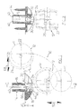
- the castor assembly 10 shown in Figs.1 and 2 comprises a castor 12 (shown in dotted outline) and a mounting bracket 14. As seen in Fig.1, the castor 12 is movable relative to the mounting bracket 14 between a use position identified as "U” and a storage or transport position identified as "T".
- the mounting bracket 14 has a socket 16 and a mounting portion 18. It will be understood that (in common with prior art castor assemblies) the socket 16 is located within a hole or recess formed in the bottom surface of the bed to which the castor is to be fitted (see the surface 20), and the mounting portion 18 lies upon that surface and can be secured thereto by way of screws or the like (see Fig.2). The surface 20 therefore represents that part of the bed to which the mounting bracket is secured (or is to be secured).
- the surface 20 may be the bottom peripheral surface of the bed, in which case in this embodiment the castor in its transport position will project beyond the bottom of the bed by a distance D which is only slightly greater than the depth of the mounting portion 18 of the mounting bracket 14.
- the surface 20 can be inside the peripheral surface of the bed, i.e. the surface 20 may lie within a recess or rebate in the bed, so that the castor in its transport position projects beyond the bottom of the bed by a distance less than D, or if desired does not project at all (depending upon the depth of the recess or rebate).
- a suitable recess can typically be provided without difficulty; and on a bed for example it is known that the surface 20 would be provided by one of the frame members providing the structural strength of the bed, the mounting bracket 14 being positionable and orientable so that the castor 12 in its transport position T lies between the frame members.
- the castor comprises a wheel 22 mounted upon an axle 26 (see Fig. 2) carried by a support bracket 24.
- the support bracket 24 is connected to a shaft 30 which can be located in the socket 16 of the mounting bracket 14.
- the shaft 30 is rotatable within the socket 16, but it is more typical that the support bracket 24 can swivel about the shaft 30.
- the present embodiment utilises the latter arrangement, as will be apparent from the following description, but it is possible for the present invention to be utilised also with the former arrangement if desired.
- the shaft 30 is better seen in Figs. 7 and 8. It has a first end 32 adapted to cooperate with internal components in the support bracket 24, the first end being designed to allow the support bracket 24 to rotate substantially freely relative to the shaft 30, and yet be substantially permanently secured thereto.
- the shaft 30 also has an annular collar 34, and at its other end a pair of lugs or keys 36, the purpose of the collar 34 and lugs 36 being explained below.
- the socket 16 includes two channels or key-ways 40 (only one of which is seen in the sectional view of Fig.1, but both channels are visible in Figs. 2 and 4, and shown in dotted outline in Fig.3).
- the channels 40 can accommodate respective lugs 36.
- the lugs 36 and channels 40 in this embodiment serve substantially to prevent rotation of the shaft 30 about its longitudinal axis A-A, but allow the shaft 30 to slide longitudinally within the socket 16.
- the socket 16 can open out at its end opposed to the mounting portion 18 to allow rotation of the shaft 30 in the use position of the castor.
- the mounting bracket 14 includes a cap member 42, which is present in Figs. 1-3 and absent in Figs. 4-6, and shown in detail in Figs. 9 and 10.
- the cap member 42 is retained adjacent the socket 16 by a lip 44, and when so retained presents a substantially flat surface 46 upon which the collar 34 can lie.
- the shaft 30 lies within the socket 16, with the lugs 36 lying within the respective channels 40, and the collar 34 lying against the surface 46 of the cap member.
- the weight of the bed acts through the collar 34 upon the cap member 42 and helps to retain the cap member 42 in position in the mounting bracket 14.
- the cap member 42 has an opening 50 (Figs.3, 9) which can accommodate the shaft 30, and in particular which can accommodate movement of the shaft relative to the mounting bracket 14 in the longitudinal direction as shown by the arrow 52 of Fig.1.
- the opening 50 is smaller than the lugs 36, so that the cap member 42 limits the longitudinal movement of the shaft 30, and retains the shaft in connection with the mounting bracket 14.
- the cap member 42 does, however, have its own channels 52 (Fig. 10) which can accomodate the lugs 36, and into which the lugs 36 are moved when the shaft 30 is moved to its most extended longitudinal position relative to the mounting bracket 14. Accordingly, it is the ends 54 of the channels 52 which are engaged by the lugs 36 and which therefore limit the outward longitudinal movement of the shaft 30.
- the channels 52 of the cap member include a curved surface 56.
- the castor When the castor is to be moved from its use position U to its transport position T it is first pulled outwardly so that the shaft 30 moves longitudinally relative to the socket 16. During this movement, the lugs 36 firstly move along the channels 40 in the socket 16 and subsequently leave the channels 40 and enter the channels 52 of the cap member 42. When the shaft 30 has been moved to its most extended position, the castor is in its first intermediate position, with the castor wheel 22 in the position shown I in Fig.1.
- the lugs 36 engage the ends 54 of the channels 52, and lie alongside the curved surface 56 of each channel 52.
- the curved surfaces 56 of the channels 52, and the corresponding recesses 60 in the body of the mounting member 14, allow the lugs 36 sufficient freedom of movement that the shaft 30 can then be pivoted through approximately 90° from its first intermediate position I to a second intermediate position (not shown) adjacent the transport position T.
- the shaft and castor are movable to the left (as drawn in Fig.1 - see the arrow 68) by a small distance.
- This small movement is not essential, but is preferred, since it ensures that the castor 12 will not pivot back to its first intermediate position (e.g. under the influence of gravity) without undergoing the reverse small movement first.
- the small movement is accommodated by the extension 62 of the curved surface 56 of the cap member 42, and the recess 60 in the body of the mounting bracket 14, which allow the end of the shaft 30 and the lugs 36 to move slightly out of alignment with the socket 16.
- the mounting portion 18 of the mounting bracket 14 is not completely annular, and includes an opening 64.
- the cap member 42 is not completely annular but includes an opening 66.
- the purpose of the openings 64 and 66 is to allow pivoting movement of the shaft 30, i.e. when the castor 12 is pivoted into its second intermediate position and transport position T respective parts of the shaft 30 lie within the openings 64 and 66.
- the opening 64 includes a pair of opposed lips 70 which help to retain the shaft 30 when the castor is in its transport position T.
- the shaft 30 must be forced past the lips 70.
- the force need not be great, but should desirably exceed the force of gravity acting upon the castor 12 so that the castor 12 does not pivot back towards its first intermediate position I by gravity alone.
- the mounting bracket 14 will be made of plastics material, and the shaft 30 of metal, the mounting bracket being sufficiently resilient to allow the shaft 30 to be forced past the lips 70.
- the pre-assembled castor 12 is connected to the mounting bracket 14, in the absence of the cap member 42, by way of the shaft 30 being introduced into the socket 16, with the lugs 36 entering the channels 40.
- the cap member 42 is then placed around the shaft and pressed into position past the lip 44.
- the lip 44 is also resilient and substantially prevents subsequent removal of the cap member 42.
- the castor assembly 10 may be moved to its transport position T and packaged ready for storage or transportation.
- this projection is small and readily accommodated within normal packaging materials such as shrink wrapping of the like.
- the castors When the item of furniture has been delivered to the customer, the castors may readily be moved to their use position U. Importantly, the customer is always able to move the castor back to its transport position T should this be required. Also, because the castor assembly 10 is fully assembled at the manufacturing location, any damaged or badly-manufactured components can be identified (and replaced or repaired) at the manufacturing location and not at the customer's premises.
- the shaft 30 is substantially free to move in the direction of its longitudinal axis relative to the socket 16. In such circumstances, if the bed is lifted the castor may move from its use position towards its first intermediate position I. This may not be desirable, and it may therefore be desired to incorporate a retaining lip or the like within the socket 16, or otherwise to increase the friction between the shaft and socket, so as (temporarily) to retain the castor in its use position whether or not the weight of the bed is acting upon it.
Landscapes
- Engineering & Computer Science (AREA)
- Mechanical Engineering (AREA)
- Handcart (AREA)
- Invalid Beds And Related Equipment (AREA)
Applications Claiming Priority (2)
| Application Number | Priority Date | Filing Date | Title |
|---|---|---|---|
| GB0304240A GB0304240D0 (en) | 2003-02-25 | 2003-02-25 | Castor assembly and mounting bracket therefor |
| GB0304240 | 2003-02-25 |
Publications (2)
| Publication Number | Publication Date |
|---|---|
| EP1452341A2 true EP1452341A2 (de) | 2004-09-01 |
| EP1452341A3 EP1452341A3 (de) | 2007-03-07 |
Family
ID=9953592
Family Applications (1)
| Application Number | Title | Priority Date | Filing Date |
|---|---|---|---|
| EP04250987A Withdrawn EP1452341A3 (de) | 2003-02-25 | 2004-02-24 | Lenkrolle und Halterung dafür |
Country Status (2)
| Country | Link |
|---|---|
| EP (1) | EP1452341A3 (de) |
| GB (1) | GB0304240D0 (de) |
Family Cites Families (5)
| Publication number | Priority date | Publication date | Assignee | Title |
|---|---|---|---|---|
| US5375294A (en) * | 1993-09-17 | 1994-12-27 | Underkart Industries Of Canada Ltd. | Retractable caster assembly |
| US5636853A (en) * | 1995-12-13 | 1997-06-10 | Huang; Li-Chu C. | Baby rocking carriage |
| JP2966366B2 (ja) * | 1997-02-19 | 1999-10-25 | 株式会社大洋プラスチックス工業所 | 格納式キャスタ装置 |
| JP3083797B2 (ja) * | 1997-12-12 | 2000-09-04 | 有限会社三起工業 | キャスター |
| US6123300A (en) * | 1999-06-01 | 2000-09-26 | Chen; Kao-Fu | Dual-purpose leg support |
-
2003
- 2003-02-25 GB GB0304240A patent/GB0304240D0/en not_active Ceased
-
2004
- 2004-02-24 EP EP04250987A patent/EP1452341A3/de not_active Withdrawn
Also Published As
| Publication number | Publication date |
|---|---|
| EP1452341A3 (de) | 2007-03-07 |
| GB0304240D0 (en) | 2003-03-26 |
Similar Documents
| Publication | Publication Date | Title |
|---|---|---|
| US6250717B1 (en) | Hinge block for the arm-rest of a wheelchair for the handicapped, and a corresponding wheelchair | |
| WO2004023866A3 (en) | Milker unit detacher for rotary milking parlor | |
| AU6974998A (en) | Protective roll guard for clearing obstacles from caster wheels | |
| US11046527B2 (en) | Chain disk corner | |
| US6125504A (en) | Chair caster cover | |
| JP4241986B2 (ja) | モジュラー搬送マット用モジュールおよびモジュラー搬送マット | |
| US20120144593A2 (en) | Baby changing station | |
| EP1452341A2 (de) | Lenkrolle und Halterung dafür | |
| US5507069A (en) | Articulated caster | |
| US1743255A (en) | Roller construction | |
| US6408486B1 (en) | Hinge assembly for a sectional door | |
| US7100236B1 (en) | Buffer structured castor wheel for vacuum cleaner | |
| US11453276B2 (en) | Co-extrusion snap-fit retractable cover | |
| FR2768489A1 (fr) | Panneau articule a crochet | |
| JP3485100B2 (ja) | 移動テーブル | |
| JP2511107Y2 (ja) | キャスタ― | |
| JP2518597Y2 (ja) | 自転車折り畳み器 | |
| KR200229218Y1 (ko) | 운반기용 캐스터 | |
| US20080079338A1 (en) | Rolling support mechanism for pivoting bookcase or the like | |
| KR20220163629A (ko) | 폴딩형 pto축 보호 커버 | |
| KR102895970B1 (ko) | 캐스터 커버가 구비된 의자 | |
| JPS6225443Y2 (de) | ||
| GB2280600A (en) | Furniture supports with castor | |
| KR102232573B1 (ko) | 암롤 박스의 잠금 구조체 | |
| USRE48480E1 (en) | Baby changing station |
Legal Events
| Date | Code | Title | Description |
|---|---|---|---|
| PUAI | Public reference made under article 153(3) epc to a published international application that has entered the european phase |
Free format text: ORIGINAL CODE: 0009012 |
|
| AK | Designated contracting states |
Kind code of ref document: A2 Designated state(s): AT BE BG CH CY CZ DE DK EE ES FI FR GB GR HU IE IT LI LU MC NL PT RO SE SI SK TR |
|
| AX | Request for extension of the european patent |
Extension state: AL HR LT LV MK |
|
| PUAL | Search report despatched |
Free format text: ORIGINAL CODE: 0009013 |
|
| AK | Designated contracting states |
Kind code of ref document: A3 Designated state(s): AT BE BG CH CY CZ DE DK EE ES FI FR GB GR HU IE IT LI LU MC NL PT RO SE SI SK TR |
|
| AX | Request for extension of the european patent |
Extension state: AL LT LV MK |
|
| AKX | Designation fees paid | ||
| REG | Reference to a national code |
Ref country code: DE Ref legal event code: 8566 |
|
| STAA | Information on the status of an ep patent application or granted ep patent |
Free format text: STATUS: THE APPLICATION IS DEEMED TO BE WITHDRAWN |
|
| 18D | Application deemed to be withdrawn |
Effective date: 20070908 |