EP1451910B1 - Eclisse de raccordement pour raccorder deux portions d'un chemin de cables en fils, portion de chemin de cables en fils equipee, d'une telle eclisse et chemin de cables en fils ayant deux portions raccordees par une telle eclisse - Google Patents
Eclisse de raccordement pour raccorder deux portions d'un chemin de cables en fils, portion de chemin de cables en fils equipee, d'une telle eclisse et chemin de cables en fils ayant deux portions raccordees par une telle eclisse Download PDFInfo
- Publication number
- EP1451910B1 EP1451910B1 EP02801088A EP02801088A EP1451910B1 EP 1451910 B1 EP1451910 B1 EP 1451910B1 EP 02801088 A EP02801088 A EP 02801088A EP 02801088 A EP02801088 A EP 02801088A EP 1451910 B1 EP1451910 B1 EP 1451910B1
- Authority
- EP
- European Patent Office
- Prior art keywords
- cable tray
- fishplate
- portions
- wires
- notches
- Prior art date
- Legal status (The legal status is an assumption and is not a legal conclusion. Google has not performed a legal analysis and makes no representation as to the accuracy of the status listed.)
- Expired - Lifetime
Links
Images


Classifications
-
- H—ELECTRICITY
- H02—GENERATION; CONVERSION OR DISTRIBUTION OF ELECTRIC POWER
- H02G—INSTALLATION OF ELECTRIC CABLES OR LINES, OR OF COMBINED OPTICAL AND ELECTRIC CABLES OR LINES
- H02G3/00—Installations of electric cables or lines or protective tubing therefor in or on buildings, equivalent structures or vehicles
- H02G3/02—Details
- H02G3/04—Protective tubing or conduits, e.g. cable ladders or cable troughs
- H02G3/0437—Channels
- H02G3/0443—Channels formed by wire or analogous netting
-
- H—ELECTRICITY
- H02—GENERATION; CONVERSION OR DISTRIBUTION OF ELECTRIC POWER
- H02G—INSTALLATION OF ELECTRIC CABLES OR LINES, OR OF COMBINED OPTICAL AND ELECTRIC CABLES OR LINES
- H02G3/00—Installations of electric cables or lines or protective tubing therefor in or on buildings, equivalent structures or vehicles
- H02G3/02—Details
- H02G3/06—Joints for connecting lengths of protective tubing or channels, to each other or to casings, e.g. to distribution boxes; Ensuring electrical continuity in the joint
- H02G3/0608—Joints for connecting non cylindrical conduits, e.g. channels
-
- Y—GENERAL TAGGING OF NEW TECHNOLOGICAL DEVELOPMENTS; GENERAL TAGGING OF CROSS-SECTIONAL TECHNOLOGIES SPANNING OVER SEVERAL SECTIONS OF THE IPC; TECHNICAL SUBJECTS COVERED BY FORMER USPC CROSS-REFERENCE ART COLLECTIONS [XRACs] AND DIGESTS
- Y10—TECHNICAL SUBJECTS COVERED BY FORMER USPC
- Y10T—TECHNICAL SUBJECTS COVERED BY FORMER US CLASSIFICATION
- Y10T403/00—Joints and connections
- Y10T403/71—Rod side to plate or side
- Y10T403/7176—Resilient clip
Definitions
- the present invention generally relates to the paths of wire cables.
- these wire cable trays include, in the form of two types of yarn, namely, on the one hand, yarn longitudinal, commonly called warp yarns, that run, longitudinally, rectilinearly or almost rectilinearly, over their entire length, and, on the other hand, transversely placed from place to place along these longitudinal threads, being duly subject to them, transverse threads shaped U-shaped, commonly called weft yarns, the assembly forming overall three panels, in practice plans or substantially plans, namely a bottom panel and two side panels.
- yarn longitudinal commonly called warp yarns
- warp yarns that run, longitudinally, rectilinearly or almost rectilinearly, over their entire length
- transverse threads shaped U-shaped commonly called weft yarns
- wire cable trays are commonly used to ensure, at the way of chute, support, housing and cable protection electric or similar.
- electrical cables we mean indeed here, and in what follows, no only cables specific to the transport and distribution of energy electric, but also cables and fibers specific to a transmission information in an electrical, optical or other manner.
- the wire cable trays have many advantages that make them appreciate electricians installers, and, in particular, benefits of ease of installation, and therefore of economy, of flexibility, electrical cables that can be removed by any of their meshes, of transparency, and, therefore, of locating electrical cables, ventilation, cleanliness and safety, both for electrical cables and for users, and performance.
- a cable tray comprises several portions; he consists of several sections assembled end-to-end or at an angle between them or making a derivation in T, X, Y or other; the portions are therefore different sections or are the same section: in the first case, the portions are assembled end to end; in the second case, a panel side of the section was cut to make the two portions: the splint is set up in the section after shaping the other side panel; we can thus realize curves of various rays: indeed, although this one depending on the width of the cable tray, if a splint does not allow to achieve the desired angle, the side panel of the section can be sectioned into several places and a splint set up in each section.
- US-B1-6247871 discloses a splice connection type of the type mentioned above.
- the present invention aims to propose a splint of connection which makes it possible to connect very quickly two portions of such cable trays made of wires, without the use of screws or bolts, said splint not being aggressive, can be pre-mounted on one of the portions of the road of cables, and even recovered after use.
- a connection splice for connecting two portions of a wire raceway consisting of wires of two different types, on the one hand, warp threads and, on the other hand, weft threads, the connection said two portions, so that their assembly, being carried out by through their end-placed weft yarns, is characterized by the fact that it comprises a U-shaped body having two wings and a soul, said wings each having at least two indentations with parallel edges, the notches of one wing facing the notches of the other wing, the edges parallel to each other by an indentation being parallel to the parallel edges between them from the other notch, one of the edges of at least one of the notches facing a so-called locking tab, said locking tabs being adapted to be folded folded, towards the inside of the U-shaped body, on each of said end-fed weft yarns.
- At least one locking tab allows the assembly rotating the splint on a portion of the raceway.
- the soul of the U-shaped body is U-shaped open, the wings U-shaped body extending from the soul into the concavity of said U-shaped core open.
- one of the U-shaped wings of the U-shaped body carries both legs locking.
- the locking tabs extend before folding to locking, perpendicular to the planes of the wings.
- the indentations extend perpendicular to the bottom, which is plan, the open U of the soul.
- the lateral parts of the open U constituting the soul of the body extend from the plane background by making an angle of the order of 120 degrees.
- each wing has four indentations.
- the distances between two adjacent indentations are uneven.
- Another subject of the invention is a cable tray made of wires having two portions connected by at least one connecting splice as above.
- the two portions of the cable tray are two independent sections assembled end to end; alternatively, the two portions of the cable trays constitute one and the same section of a cable tray, one of which side panel was sectioned, and the two portions are connected by a connection splice, the splice having been put in place in said section after shaping the other side panel, which allows to realize a elbow on the cable tray.
- the splice is mounted by its notches on wires weft, and facing each other, of the two cable trays, the legs being folded on said wings; the splint is mounted on the weft threads from inside the cable tray, its soul being located inside it.
- the splint extends between two warp yarns.
- the width of the soul of the U-shaped body of the splint is globally equal, at the mounting clearance, to the distance between the two wires chain between which it extends.
- Another object of the invention is a portion of cable tray son equipped with at least one connection splice as above, said splint being pivotally mounted about a wing of an end weft yarn and extending inside the portion of the cable tray along its panel lateral defined in particular by said wing.
- connection splice 30 intended to connect one after the other two portions of cable tray 10, 20 son, Figures 4 to 6.
- These cable tray portions 10, 20 into wires comprise, so known per se, in mesh form, threads of two different types, namely, with regard to the portion 10, the longitudinal threads 11 running longitudinally rectilinearly or sensitively rectilinear throughout its length and, on the other hand, transversely placed from place to place, following a not regular, along these longitudinal wires 11, being duly subject to these, transverse son 12 shaped U, the assembly forming overall, in the manner of a chute, three panels 13, 14, namely a bottom panel 13 and two side panels 14.
- the son 11, 12 are metal son, more precisely in steel, and at their crossing they are subjected to each other by welding.
- the wires 11, 12 intersect at different levels; right here, the longitudinal threads 11 extend outside the transverse threads 12.
- all the wires 11, 12 are wires round, that is to say that their cross section is circular.
- the diameter of the cross section is the same for all sons, but it is not necessarily always so.
- the bottom panel 13 does not have of longitudinal wire 11 and each of the side panels has only two wires longitudinal 11, namely an intermediate longitudinal thread 11, which intervenes substantially at mid-height and a longitudinal wire 11 of edge.
- longitudinal son 11 may be different; likewise, the bottom panel 13 may comprise longitudinal threads 11 and their number can be any.
- the portion 20 of the cable tray is identical to the portion 10 and its constituent elements bear the same references as those of the portion 10 increased by 10.
- transverse wires 12, 22 are U-shaped, 15, 25 their wings and 16, 26 their soul, respectively.
- the longitudinal threads 11, 21 are commonly called warp yarns, and transverse threads 12, 22 weft threads.
- the splice splice 30 comprises a U-shaped body 31 having two wings 32, 34 and a soul 33.
- the wings 32,34 each comprise two indentations with parallel edges.
- the wing 32 comprises two notches 32A, 32B with edges parallel; the mutually parallel edges of the notch 32A or 32B, are parallel to the mutually parallel edges of the notch 32B, or 32A.
- One of the edges of the indentations 32A, 32B carries a tab called locking, respectively 35A, 35B; here, the legs 35A and 35B are worn by the edges farthest from each other notches 32A, 32B.
- the wing 34 also has two notches 34A, 34B with edges parallel; the edges parallel to each other of the notch 34A, or 34B, are parallel to the edges parallel to each other of the notch 34B, or 34A.
- the notches 34A, 34B are not provided with locking tabs in the example shown but it could be otherwise.
- the notches 32A and 32B, on the one hand, and the notches 34A and 34B, on the other hand, are arranged vertically, with respect to FIG. right of others, facing each other.
- the notches 32A, 32B, 34A, 34B are adapted to receive the wings 15, 25 of the weft yarns 12, 22 of the cable trays 10 and 20, as described below. ; therefore, their width is planned accordingly.
- the core 33 of the body 31 of the splint 30 is open U-shaped; wings 32, 34 of the body 31 extend, from the soul 33, into the concavity of said soul 33 U-shaped open; the lateral parts of the open U extend from the bottom of said U open, here planned flat, making between them an angle of the order of 120 degrees.
- the notches 32A, 32B, 34A, 34B are generally perpendicular to the flat bottom of said open U.
- the lateral parts of the open U are connected to the flat bottom of it according to rounded, non-aggressive areas.
- locking tabs 35A, 35B extend inside the body 31 of the splint 30; here they extend, before folding for locking, perpendicular to the planes of wings 32 and 34, which are parallel to each other.
- Such a splice is implemented as follows.
- the two portions 10 and 20 are here set in alignment, the weft son 12 and 22 placed end facing each other; two ribs 30 are mounted, from the inside of the portions 10 and 20, so as to receiving in their notches 32A-34A and 32B-34B the wings 15, 25 of said wires weft 12 and 22.
- the locking tabs 35A, 35B are, by folding, folded over the wings 15, 25 weft son 12 and 22, which locks the ribs 30 by said wings 15, 25 of the weft threads 12, 22 and thus the connection two portions 10, 20.
- both splints 30 rotating around the wings of the weft thread at the end of a portion folding on the wings of said weft thread the corresponding locking tab; in this way, the splints 30 are rotatably mounted around said wings; for the storage, it is advantageous to rotate the splints 30 around said wings in particular by extending them along the side panels 14; the part The cable tray can be delivered with pre-assembled splints.
- the widths of the notches of the splints are sufficient for receive these different diameters and the edge of the locking tabs intended to cooperate with the wings of the weft yarns is inclined relative to the hinge of folding of the leg, that is to say it is not orthogonal, so that the interlocking is effective for these different wire diameters.
- the splints being arranged between two wires chain, we arrange for their height, namely the width of the soul of their U-shaped body 31, which is practically equal to the distance separating these two wires chain: in this way, the wedging of the ribs along the wings of the weft son is assured.
- Figures 7 to 13 show a splice variant according to the invention.
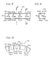
- edges of the notches 132A, 132B, 132C, 132D and 134A, 134B, 134C, 134D are parallel to each other and one of the edges of each notch of one of the wings carries a locking tab, these respectively bearing the references 135A, 135B, 135C, 135D.
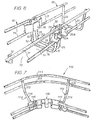
- FIG. 7 illustrates the use of a fishplate according to the invention with a view to make a change of direction of a cable tray, ie a elbow.
- the section 110 as shown laterally two longitudinal threads 111; on one side, the two longitudinal threads have been sectioned to leave room for a splint 130 while on the other side, the longitudinal son were bent to achieve the elbow.
- the soul 133 of the body 131 of the splint 130 is U-shaped open, the lateral parts of which have been almost halfway folded slightly inwards, said soul 133 having a shape polygonal with 5 sides.
- the change of direction of the cable tray is of the order of 130 degrees.
- the splice 30 of FIGS. 1 to 6 has been shown in connection with two portions of cable trays in the extension of one another; she could of course be used for the realization of an elbow, as shown by splice 130; the splint 30 as shown could lead to a change of direction of the order of 120 degrees.
Landscapes
- Engineering & Computer Science (AREA)
- Architecture (AREA)
- Civil Engineering (AREA)
- Structural Engineering (AREA)
- Details Of Indoor Wiring (AREA)
- Light Guides In General And Applications Therefor (AREA)
- Cable Accessories (AREA)
- Multi-Conductor Connections (AREA)
- Installation Of Indoor Wiring (AREA)
- Electric Cable Arrangement Between Relatively Moving Parts (AREA)
- Mechanical Coupling Of Light Guides (AREA)
- Mutual Connection Of Rods And Tubes (AREA)
Description
- la figure 1 est une vue en élévation d'une éclisse de raccordement selon l'invention ;
- la figure 2 est une vue en coupe selon II-II de la figure 1 ;
- la figure 3 est une vue selon la flèche III de la figure 1 ;
- la figure 4 est une vue montrant le raccordement de deux portions de chemin de câbles par l'éclisse des figures 1 à 3 ;
- la figure 5 est une vue selon la flèche V de la figure 4 ;
- la figure 6 est une vue analogue à la figure 4 mais en perspective ;
- la figure 7 est analogue à la figure 6 mais représente une variante ;
- la figure 8 est une vue en élévation de l'éclisse de la variante de la figure 7;
- la figure 9 est une vue en coupe selon IX-IX de la figure 8 ;
- la figure 10 est une vue selon la flèche X de la figure 8 ;
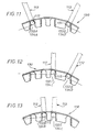
- la figure 11 est une vue partielle de dessus illustrant le montage de la figure 7 ;
- les figures 12 et 13 illustrent deux autres positions de montage de l'éclisse des figures 7 à 11.
Claims (17)
- Eclisse de raccordement pour raccorder deux portions (10,20,110) d'un chemin de câbles en fils constitué de fils de deux types différents, d'une part, des fils de chaíne (11,21,111) et, d'autre part, des fils de trame (12,22,112), le raccordement desdites deux portions (10,20,110), ainsi donc que leur assemblage, étant effectué par l'intermédiaire de leurs fils de trame (12,22,112) placés en bout, caractérisée par le fait qu'elle comprend un corps (31,131) en forme de U ayant deux ailes (32,132,34,134) et une âme (33,133), lesdites ailes (32-132,34-134) comportant chacune au moins deux échancrures (32A,.....132A.... 34A....134A.....) à bords parallèles, les échancrures (32A....132A....) d'une aile (32,132) faisant face aux échancrures (34A.....134A) de l'autre aile (34,134), les bords parallèles entre eux d'une échancrure étant parallèles aux bords parallèles entre eux de l'autre échancrure, l'un des bords d'au moins l'une des échancrures se faisant face portant une patte (35A.....135A.....) dite de verrouillage, lesdites pattes de verrouillage étant adaptées à être par pliage rabattues, vers l'intérieur du U du corps (31,131) en U, sur chacun desdits fils de trame (12,22,112) placés en bout.
- Eclisse de raccordement selon la revendication 1, caractérisée par le fait qu'au moins une patte de verrouillage permet le montage à rotation de l'éclisse (30,130) sur une portion (10,20,110) du chemin de câbles.
- Eclisse de raccordement selon l'une des revendications 1 ou 2, caractérisée par le fait que l'âme (33,133) du corps en U (31,131) est en forme de U ouvert, les ailes (32-132,34-134) du corps en U (31-131) s'étendant depuis l'âme (33,133) dans la concavité de ladite âme (33,133) en U ouvert.
- Eclisse de raccordement selon l'une des revendications 1 à 3, caractérisée par le fait que l'une (34-134) des ailes du U du corps en U (31-131) porte les pattes (35A.....135A....) de verrouillage.
- Eclisse de raccordement selon l'une des revendications 1 à 4, caractérisée par le fait que les pattes de verrouillage (35A... 135A....) s'étendent, avant pliage pour verrouillage, perpendiculairement aux plans des ailes (32-132,34-134).
- Eclisse de raccordement selon la revendication 3 prise seule ou en combinaison avec l'une des revendications 4 ou 5, caractérisée par le fait que les échancrures (32A....132A.....34A.....134A....) s'étendent perpendiculairement au fond, qui est plan, du U ouvert de l'âme (33,133).
- Eclisse de raccordement selon la revendication 6, caractérisée par le fait que les parties latérales du U ouvert constituant l'âme (33) du corps (31) s'étendent depuis le fond plat en faisant entre elles un angle de l'ordre de 120 degrés.
- Eclisse de raccordement selon l'une des revendications 1 à 7, caractérisée par le fait que chaque aile (132,134) comporte quatre échancrures (132A.... 134A....).
- Eclisse de raccordement selon la revendication 8, caractérisée par le fait que les distances entre deux échancrures (132A....... 134A......) adjacentes sont inégales.
- Chemin de câbles en fils ayant deux portions en regard raccordées par au moins une éclisse de raccordement, caractérisé par le fait que ladite éclisse de raccordement est selon l'une des revendications 1 à 9.
- Chemin de câbles en fils selon la revendication 10, caractérisé par le fait que les deux portions du chemin de câbles sont deux tronçons indépendants assemblés bout à bout.
- Chemin de câbles en fils selon la revendication 10, caractérisé par le fait que les deux portions du chemin de câbles constituent un même tronçon d'un chemin de câbles, dont un panneau latéral a été sectionné, et que les deux portions sont raccordées par une éclisse de raccordement, l'éclisse ayant été mise en place dans ladite section après mise en forme de l'autre panneau latéral, ce qui permet de réaliser un coude sur le chemin de câbles.
- Chemin de câbles selon l'une des revendications 10 à 12, caractérisé par le fait que l'éclisse (30,130) est montée par ses échancrures sur des fils de trame (12,22,112) placés en bout, et se faisant face, des deux portions (10,20,110), les pattes (35A....135A....) étant rabattues sur lesdites ailes (15, 25,115).
- Chemin de câbles selon la revendication 13, caractérisé par le fait que l'éclisse (30,130) est montée sur les fils de trame (12,22,112) depuis l'intérieur du chemin de câbles, son âme (33,133) étant située à l'intérieur de celui-ci.
- Chemin de câbles selon l'une des revendications 10 à 14, caractérisé par le fait que l'éclisse (30,130) s'étend entre deux fils de chaíne (11,21,111).
- Chemin de câbles selon la revendication 15, caractérisé par le fait que la largeur de l'âme (33,133) du corps en U de l'éclisse (30,130) est globalement égale, au jeu de montage près, à la distance qui sépare les deux fils de chaíne (11,21,111) entre lesquels elle s'étend.
- Portion de chemin de câbles en fils, caractérisée par le fait qu'elle est équipée d'au moins une éclisse de raccordement selon l'une des revendications 1 à 9, ladite éclisse (30,130) étant montée à pivotement autour d'une aile (15,25,115) d'un fil de trame (12,22,112) en bout et s'étendant à l'intérieur de la portion du chemin de câbles (10,20,110) le long de son panneau latéral (14,24,114) défini notamment par ladite aile (15,25,115).
Applications Claiming Priority (3)
| Application Number | Priority Date | Filing Date | Title |
|---|---|---|---|
| FR0115777A FR2833420B1 (fr) | 2001-12-06 | 2001-12-06 | Eclisse de raccordement pour raccorder deux portions d'un chemin de cables en fils, portion de chemin de cables en fils equipee d'une telle eclisse et chemin de cables en fils ayant deux portions raccordees par une telle eclisse |
| FR0115777 | 2001-12-06 | ||
| PCT/FR2002/004126 WO2003049247A1 (fr) | 2001-12-06 | 2002-12-02 | Eclisse de raccordement pour raccorder deux portions d'un chemin de cables en fils, portion de chemin de cables en fils equipee d'une telle eclisse et chemin de cables en fils ayant deux portions raccordees par une telle eclisse |
Publications (2)
| Publication Number | Publication Date |
|---|---|
| EP1451910A1 EP1451910A1 (fr) | 2004-09-01 |
| EP1451910B1 true EP1451910B1 (fr) | 2005-10-26 |
Family
ID=8870177
Family Applications (1)
| Application Number | Title | Priority Date | Filing Date |
|---|---|---|---|
| EP02801088A Expired - Lifetime EP1451910B1 (fr) | 2001-12-06 | 2002-12-02 | Eclisse de raccordement pour raccorder deux portions d'un chemin de cables en fils, portion de chemin de cables en fils equipee, d'une telle eclisse et chemin de cables en fils ayant deux portions raccordees par une telle eclisse |
Country Status (11)
| Country | Link |
|---|---|
| US (1) | US20050063775A1 (fr) |
| EP (1) | EP1451910B1 (fr) |
| JP (1) | JP4160904B2 (fr) |
| AT (1) | ATE308140T1 (fr) |
| AU (1) | AU2002364806A1 (fr) |
| DE (1) | DE60206960T2 (fr) |
| DK (1) | DK1451910T3 (fr) |
| ES (1) | ES2250743T3 (fr) |
| FR (1) | FR2833420B1 (fr) |
| MX (1) | MXPA04005136A (fr) |
| WO (1) | WO2003049247A1 (fr) |
Cited By (2)
| Publication number | Priority date | Publication date | Assignee | Title |
|---|---|---|---|---|
| US9178343B2 (en) | 2010-05-19 | 2015-11-03 | Panduit Corp. | Cable tray cable routing system |
| US10483733B2 (en) | 2012-10-09 | 2019-11-19 | Thomas & Betts International Llc | Joint strip |
Families Citing this family (30)
| Publication number | Priority date | Publication date | Assignee | Title |
|---|---|---|---|---|
| FR2821211B1 (fr) * | 2001-02-16 | 2003-07-25 | Krieg & Zivy Ind | Eclisse de raccordement pour chemins de cables en fils, chemin de cables en fils equipe d'une telle eclisse et ensemble de chemins de cables en fils raccordes par une telle eclisse |
| FR2883108B1 (fr) * | 2005-03-14 | 2007-06-08 | Icm Group Sa | Eclisse de chemin de cables en fils |
| FR2888683B1 (fr) * | 2005-07-12 | 2007-10-12 | Icm Group Sa | Eclisse de raccordement de troncons de chemin de cables |
| EP1793464A1 (fr) * | 2005-12-02 | 2007-06-06 | Legrand S.p.A. | Pièce de connexion rapide pour chemins de câbles en treillis |
| FR2894726B1 (fr) * | 2005-12-13 | 2008-02-29 | Icm Group Sa | Chemin de cables en fils, notamment chemin de cables a usage domestique |
| ES1067626Y (es) * | 2008-04-04 | 2008-09-01 | Schneider Electric Espana Sa | Brida de union rapida para bandejas portacables |
| US8263863B2 (en) * | 2009-01-05 | 2012-09-11 | Chatsworth Products, Inc. | Cable radius anchor for wire mesh basket tray |
| ES2322787B1 (es) * | 2009-01-30 | 2010-07-07 | Schneider Electric España, S.A. | Dispositivo de union para bandejas de rejilla y tramo de bandejas de rejilla unidas mediante dicho dispositivo. |
| US7903924B2 (en) * | 2009-04-09 | 2011-03-08 | M P Husky, Llc | Connector for splicing and hanging cable trays |
| GB2482450A (en) * | 2009-05-08 | 2012-02-01 | Birmingham Barbed Tape Ltd | Modular fence panel |
| FR2948504B1 (fr) | 2009-07-27 | 2012-12-14 | Cts Cable Tray Systems Sas | Systeme de verrouillage pour chemins de cables et chemins de cables munis d'un tel systeme |
| US20120227675A1 (en) * | 2011-03-10 | 2012-09-13 | David Link | Pet enclosure with dual axes swivel connector |
| FR2976334B1 (fr) * | 2011-06-07 | 2015-06-19 | Legrand France | Accessoire d'angle pour chemins de cables en fils |
| FR2976335B1 (fr) * | 2011-06-07 | 2013-07-05 | Legrand France | Accessoire d'angle pour chemins de cables en fils |
| ES2396209B1 (es) * | 2011-07-14 | 2014-01-30 | Valdinox, S.L. | Tramo de bandeja portacables. |
| EP2605350B1 (fr) | 2011-12-15 | 2015-08-05 | Niedax France | Système de verrouillage de deux tronçons de chemin de câbles |
| US9293899B2 (en) | 2013-02-12 | 2016-03-22 | Panduit Corp. | Transition splice for cable routing system |
| US20150078809A1 (en) * | 2013-09-15 | 2015-03-19 | Richard Gregg Winn | Cable tray splice and support |
| ES2555330B1 (es) * | 2014-05-27 | 2016-09-26 | Valdinox, S.L. | Perfeccionamientos para tramos de bandeja portacables |
| FR3040830B1 (fr) * | 2015-09-08 | 2018-09-07 | Niedax France | Piece de liaison et element de raccordement pour chemins de cables |
| KR101836393B1 (ko) * | 2017-09-29 | 2018-03-08 | (주)예다종합설계감리사무소 | 통신케이블 트레이 |
| US11174633B2 (en) * | 2020-03-09 | 2021-11-16 | Trango-Sys Ltd. | Modular construction system and method of use thereof |
| FR3108210B1 (fr) * | 2020-03-13 | 2022-04-01 | Legrand France | Tronçon de chemin de câble s présentant une extrémité éclissée |
| US11398720B2 (en) * | 2020-04-01 | 2022-07-26 | Cablofil, Inc. | Flex-fitting cable tray |
| US11677221B2 (en) | 2020-10-22 | 2023-06-13 | Panduit Corp. | Locking snap-on splice for cable basket |
| US11909154B1 (en) | 2021-03-08 | 2024-02-20 | Chatsworth Products, Inc. | Endcap for establishing electrical bonding connection |
| EP4080701A1 (fr) | 2021-04-20 | 2022-10-26 | Erico International Corporation | Pinces de chemin de câbles et leurs procédés d'utilisation |
| EP4228110A1 (fr) | 2022-02-11 | 2023-08-16 | Erico International Corporation | Pince d'épissure pour chemins de câbles |
| EP4666357A1 (fr) | 2023-02-16 | 2025-12-24 | Erico International Corporation | Sortie de chemin de câbles |
| KR102691565B1 (ko) * | 2023-12-21 | 2024-08-05 | 김태진 | 케이블 트레이 조립체 |
Family Cites Families (17)
| Publication number | Priority date | Publication date | Assignee | Title |
|---|---|---|---|---|
| US871210A (en) * | 1906-07-25 | 1907-11-19 | Robert A Cummings | Connecting and spacing clip. |
| US1362707A (en) * | 1919-11-01 | 1920-12-21 | Henry H Lampert | Bar-support |
| US2921607A (en) * | 1957-02-11 | 1960-01-19 | Jack E Caveney | Wiring duct |
| US3294351A (en) * | 1965-04-19 | 1966-12-27 | Nashville Wire Products Mfg Co | Gondola shelf and bracket |
| DE1790019C2 (de) * | 1968-08-28 | 1978-03-16 | Rieth & Co, 7312 Kirchheim | Stationär verlegbarer Kabel- oder Leitungsträger |
| US3806994A (en) * | 1972-08-04 | 1974-04-30 | P Lankford | Fastening device for reinforcing rods |
| US4598523A (en) * | 1984-01-17 | 1986-07-08 | Tolliver Wilbur E | Reinforcement support spacer |
| US4715741A (en) * | 1986-07-21 | 1987-12-29 | Amco Corporation | Clip for coupling shelf assemblies |
| DE4138064C1 (fr) * | 1991-11-19 | 1993-05-06 | Kreuzer Gmbh + Co Ohg, 8039 Puchheim, De | |
| FR2687207B1 (fr) * | 1992-02-11 | 1995-05-24 | Mavil | Eclisses pour treillis en fils soudes. |
| FR2727712A1 (fr) * | 1994-12-01 | 1996-06-07 | Metal Deploye Sa | Element porteur pour structures en treillis |
| US5797233A (en) * | 1995-12-29 | 1998-08-25 | Hascall; Karl B. | Pre-spaced time-saving track for mounting studs for construction of drywall and other wall surfaces |
| US5868263A (en) * | 1996-09-11 | 1999-02-09 | Metal Masters Foodservice & Equipment Co., Inc. | Wall mounted storage system |
| DE19815047B4 (de) * | 1997-09-24 | 2006-08-17 | Obo Bettermann Gmbh & Co. Kg | Anordnung zur schraubenlosen Verbindung von Gitterkabelbahnen |
| FR2815091B1 (fr) * | 2000-10-11 | 2003-08-15 | Krieg & Zivy Ind | Attache du suspension |
| FR2821211B1 (fr) * | 2001-02-16 | 2003-07-25 | Krieg & Zivy Ind | Eclisse de raccordement pour chemins de cables en fils, chemin de cables en fils equipe d'une telle eclisse et ensemble de chemins de cables en fils raccordes par une telle eclisse |
| US6918498B2 (en) * | 2003-05-06 | 2005-07-19 | Chicago Display Marketing Corporation | Method and apparatus for a wire shelf hooking onto slotted brackets |
-
2001
- 2001-12-06 FR FR0115777A patent/FR2833420B1/fr not_active Expired - Fee Related
-
2002
- 2002-12-02 DK DK02801088T patent/DK1451910T3/da active
- 2002-12-02 EP EP02801088A patent/EP1451910B1/fr not_active Expired - Lifetime
- 2002-12-02 AT AT02801088T patent/ATE308140T1/de not_active IP Right Cessation
- 2002-12-02 AU AU2002364806A patent/AU2002364806A1/en not_active Abandoned
- 2002-12-02 WO PCT/FR2002/004126 patent/WO2003049247A1/fr not_active Ceased
- 2002-12-02 DE DE60206960T patent/DE60206960T2/de not_active Expired - Lifetime
- 2002-12-02 MX MXPA04005136A patent/MXPA04005136A/es active IP Right Grant
- 2002-12-02 ES ES02801088T patent/ES2250743T3/es not_active Expired - Lifetime
- 2002-12-02 US US10/495,873 patent/US20050063775A1/en not_active Abandoned
- 2002-12-02 JP JP2003550330A patent/JP4160904B2/ja not_active Expired - Fee Related
Cited By (4)
| Publication number | Priority date | Publication date | Assignee | Title |
|---|---|---|---|---|
| US9178343B2 (en) | 2010-05-19 | 2015-11-03 | Panduit Corp. | Cable tray cable routing system |
| US9853428B2 (en) | 2010-05-19 | 2017-12-26 | Panduit Corp. | Cable tray cable routing system |
| US11056865B2 (en) | 2010-05-19 | 2021-07-06 | Panduit Corp. | Cable tray cable routing system |
| US10483733B2 (en) | 2012-10-09 | 2019-11-19 | Thomas & Betts International Llc | Joint strip |
Also Published As
| Publication number | Publication date |
|---|---|
| ATE308140T1 (de) | 2005-11-15 |
| FR2833420B1 (fr) | 2004-07-02 |
| JP4160904B2 (ja) | 2008-10-08 |
| JP2006503527A (ja) | 2006-01-26 |
| EP1451910A1 (fr) | 2004-09-01 |
| MXPA04005136A (es) | 2004-08-11 |
| AU2002364806A1 (en) | 2003-06-17 |
| DE60206960T2 (de) | 2006-07-13 |
| WO2003049247A1 (fr) | 2003-06-12 |
| DE60206960D1 (de) | 2005-12-01 |
| FR2833420A1 (fr) | 2003-06-13 |
| ES2250743T3 (es) | 2006-04-16 |
| US20050063775A1 (en) | 2005-03-24 |
| DK1451910T3 (da) | 2006-03-06 |
Similar Documents
| Publication | Publication Date | Title |
|---|---|---|
| WO2003049247A1 (fr) | Eclisse de raccordement pour raccorder deux portions d'un chemin de cables en fils, portion de chemin de cables en fils equipee d'une telle eclisse et chemin de cables en fils ayant deux portions raccordees par une telle eclisse | |
| EP1360749B1 (fr) | Eclisse de raccordement pour chemins de cables en fils, chemin de cables en fils equipe d'une telle eclisse et ensemble de chemins de cables en fils raccordes par une telle eclisse | |
| EP1224719B1 (fr) | Dispositif de guidage d'au moins un element longiligne souple, tel que cable ou autre, a contour substantiellement ferme | |
| CA2517696C (fr) | Dispositif de fixation d`un fil sur un element porteur muni d`au moins une ouverture | |
| EP1000284A1 (fr) | Chemin de cables en fils equipe d'au moins un accessoire de fixation, et accessoire de fixation correspondant | |
| FR2612539A1 (fr) | Poutrelle de support de plafond | |
| CA2600260A1 (fr) | Eclisse de raccordement pour chemin de cables en fils | |
| EP0235039B1 (fr) | Pièce de jonction permettant d'assembler par rapprochement deux profilés tubulaires coupés à un angle donné | |
| EP2719040B1 (fr) | Accessoire d'angle pour chemins de cables en fils | |
| FR2626723A1 (fr) | Dispositif deformable pour relier des conduits de distribution d'energie electrique | |
| FR2766904A1 (fr) | Profile a section transversale du type en c susceptible d'etre associe a lui-meme par emboitement | |
| EP2719038B1 (fr) | Accessoire d'angle pour chemins de cables en fils | |
| EP1465311A1 (fr) | Console de support de chemin de câbles | |
| FR2738623A1 (fr) | Luminaire muni d'un louvre perfectionne | |
| FR2795250A1 (fr) | Deversoir pour chemin de cables en fils et chemin de cables en fils equipe d'au moins un tel deversoir | |
| EP1150407B1 (fr) | Troncon de chemin à câbles en treillis de fils et chemin à câbles obtenu par assemblage d'au moins deux des dits troncons | |
| EP0745532A1 (fr) | Profilé destiné à l'assemblage des éléments de structure d'un siège tel qu'un siège d'aéronef et procédé d'assemblage utilisant ce profilé | |
| FR2741136A1 (fr) | Support de derivation, notamment pour chemin de cables en fils | |
| EP0163712A1 (fr) | Structure de batiment metallique. | |
| FR2757224A1 (fr) | Assemblage du type tenon-mortaise | |
| FR2800835A1 (fr) | Dispositif de raccordement angulaire pour chemin de cables en fils, et chemin de cables en fils equipe d'un tel dispositif | |
| EP0567371A1 (fr) | Système d'assemblage de panneaux blindés constituant une cage de Faraday | |
| EP0884815A1 (fr) | Chemin de câble de faux-plafond ou de plancher technique | |
| FR2793828A1 (fr) | Piece d'angle a desalignement pour le raccordement de deux troncons successifs d'une plinthe ou analogue | |
| FR2773832A1 (fr) | Dispositif de connexion d'elements de charpente |
Legal Events
| Date | Code | Title | Description |
|---|---|---|---|
| PUAI | Public reference made under article 153(3) epc to a published international application that has entered the european phase |
Free format text: ORIGINAL CODE: 0009012 |
|
| 17P | Request for examination filed |
Effective date: 20040515 |
|
| AK | Designated contracting states |
Kind code of ref document: A1 Designated state(s): AT BE BG CH CY CZ DE DK EE ES FI FR GB GR IE IT LI LU MC NL PT SE SI SK TR |
|
| AX | Request for extension of the european patent |
Extension state: AL LT LV MK RO |
|
| GRAP | Despatch of communication of intention to grant a patent |
Free format text: ORIGINAL CODE: EPIDOSNIGR1 |
|
| GRAS | Grant fee paid |
Free format text: ORIGINAL CODE: EPIDOSNIGR3 |
|
| GRAA | (expected) grant |
Free format text: ORIGINAL CODE: 0009210 |
|
| AK | Designated contracting states |
Kind code of ref document: B1 Designated state(s): AT BE BG CH CY CZ DE DK EE ES FI FR GB GR IE IT LI LU MC NL PT SE SI SK TR |
|
| PG25 | Lapsed in a contracting state [announced via postgrant information from national office to epo] |
Ref country code: SK Free format text: LAPSE BECAUSE OF FAILURE TO SUBMIT A TRANSLATION OF THE DESCRIPTION OR TO PAY THE FEE WITHIN THE PRESCRIBED TIME-LIMIT Effective date: 20051026 Ref country code: SI Free format text: LAPSE BECAUSE OF FAILURE TO SUBMIT A TRANSLATION OF THE DESCRIPTION OR TO PAY THE FEE WITHIN THE PRESCRIBED TIME-LIMIT Effective date: 20051026 Ref country code: IE Free format text: LAPSE BECAUSE OF FAILURE TO SUBMIT A TRANSLATION OF THE DESCRIPTION OR TO PAY THE FEE WITHIN THE PRESCRIBED TIME-LIMIT Effective date: 20051026 Ref country code: FI Free format text: LAPSE BECAUSE OF FAILURE TO SUBMIT A TRANSLATION OF THE DESCRIPTION OR TO PAY THE FEE WITHIN THE PRESCRIBED TIME-LIMIT Effective date: 20051026 Ref country code: EE Free format text: LAPSE BECAUSE OF FAILURE TO SUBMIT A TRANSLATION OF THE DESCRIPTION OR TO PAY THE FEE WITHIN THE PRESCRIBED TIME-LIMIT Effective date: 20051026 Ref country code: AT Free format text: LAPSE BECAUSE OF FAILURE TO SUBMIT A TRANSLATION OF THE DESCRIPTION OR TO PAY THE FEE WITHIN THE PRESCRIBED TIME-LIMIT Effective date: 20051026 |
|
| REG | Reference to a national code |
Ref country code: GB Ref legal event code: FG4D Free format text: NOT ENGLISH |
|
| RIN1 | Information on inventor provided before grant (corrected) |
Inventor name: BOLTZ, ROLAND |
|
| REG | Reference to a national code |
Ref country code: CH Ref legal event code: EP |
|
| REG | Reference to a national code |
Ref country code: IE Ref legal event code: FG4D Free format text: LANGUAGE OF EP DOCUMENT: FRENCH |
|
| REF | Corresponds to: |
Ref document number: 60206960 Country of ref document: DE Date of ref document: 20051201 Kind code of ref document: P |
|
| PG25 | Lapsed in a contracting state [announced via postgrant information from national office to epo] |
Ref country code: CY Free format text: LAPSE BECAUSE OF FAILURE TO SUBMIT A TRANSLATION OF THE DESCRIPTION OR TO PAY THE FEE WITHIN THE PRESCRIBED TIME-LIMIT Effective date: 20051202 |
|
| PG25 | Lapsed in a contracting state [announced via postgrant information from national office to epo] |
Ref country code: MC Free format text: LAPSE BECAUSE OF NON-PAYMENT OF DUE FEES Effective date: 20051231 Ref country code: LU Free format text: LAPSE BECAUSE OF NON-PAYMENT OF DUE FEES Effective date: 20051231 |
|
| PG25 | Lapsed in a contracting state [announced via postgrant information from national office to epo] |
Ref country code: GR Free format text: LAPSE BECAUSE OF FAILURE TO SUBMIT A TRANSLATION OF THE DESCRIPTION OR TO PAY THE FEE WITHIN THE PRESCRIBED TIME-LIMIT Effective date: 20060126 Ref country code: BG Free format text: LAPSE BECAUSE OF FAILURE TO SUBMIT A TRANSLATION OF THE DESCRIPTION OR TO PAY THE FEE WITHIN THE PRESCRIBED TIME-LIMIT Effective date: 20060126 |
|
| REG | Reference to a national code |
Ref country code: SE Ref legal event code: TRGR |
|
| GBT | Gb: translation of ep patent filed (gb section 77(6)(a)/1977) |
Effective date: 20060206 |
|
| REG | Reference to a national code |
Ref country code: DK Ref legal event code: T3 |
|
| PG25 | Lapsed in a contracting state [announced via postgrant information from national office to epo] |
Ref country code: PT Free format text: LAPSE BECAUSE OF FAILURE TO SUBMIT A TRANSLATION OF THE DESCRIPTION OR TO PAY THE FEE WITHIN THE PRESCRIBED TIME-LIMIT Effective date: 20060327 |
|
| REG | Reference to a national code |
Ref country code: ES Ref legal event code: FG2A Ref document number: 2250743 Country of ref document: ES Kind code of ref document: T3 |
|
| REG | Reference to a national code |
Ref country code: IE Ref legal event code: FD4D |
|
| PLBE | No opposition filed within time limit |
Free format text: ORIGINAL CODE: 0009261 |
|
| STAA | Information on the status of an ep patent application or granted ep patent |
Free format text: STATUS: NO OPPOSITION FILED WITHIN TIME LIMIT |
|
| 26N | No opposition filed |
Effective date: 20060727 |
|
| PG25 | Lapsed in a contracting state [announced via postgrant information from national office to epo] |
Ref country code: LI Free format text: LAPSE BECAUSE OF NON-PAYMENT OF DUE FEES Effective date: 20061231 Ref country code: CH Free format text: LAPSE BECAUSE OF NON-PAYMENT OF DUE FEES Effective date: 20061231 |
|
| REG | Reference to a national code |
Ref country code: CH Ref legal event code: PL |
|
| PGFP | Annual fee paid to national office [announced via postgrant information from national office to epo] |
Ref country code: DK Payment date: 20121123 Year of fee payment: 11 |
|
| PGFP | Annual fee paid to national office [announced via postgrant information from national office to epo] |
Ref country code: NL Payment date: 20121228 Year of fee payment: 11 |
|
| REG | Reference to a national code |
Ref country code: DK Ref legal event code: EBP Effective date: 20131231 |
|
| REG | Reference to a national code |
Ref country code: NL Ref legal event code: V1 Effective date: 20140701 |
|
| PG25 | Lapsed in a contracting state [announced via postgrant information from national office to epo] |
Ref country code: NL Free format text: LAPSE BECAUSE OF NON-PAYMENT OF DUE FEES Effective date: 20140701 |
|
| PG25 | Lapsed in a contracting state [announced via postgrant information from national office to epo] |
Ref country code: DK Free format text: LAPSE BECAUSE OF NON-PAYMENT OF DUE FEES Effective date: 20131231 |
|
| PGFP | Annual fee paid to national office [announced via postgrant information from national office to epo] |
Ref country code: CZ Payment date: 20141125 Year of fee payment: 13 |
|
| REG | Reference to a national code |
Ref country code: FR Ref legal event code: PLFP Year of fee payment: 14 |
|
| PG25 | Lapsed in a contracting state [announced via postgrant information from national office to epo] |
Ref country code: CZ Free format text: LAPSE BECAUSE OF NON-PAYMENT OF DUE FEES Effective date: 20151202 |
|
| REG | Reference to a national code |
Ref country code: FR Ref legal event code: PLFP Year of fee payment: 15 |
|
| PGFP | Annual fee paid to national office [announced via postgrant information from national office to epo] |
Ref country code: IT Payment date: 20161214 Year of fee payment: 15 Ref country code: BE Payment date: 20161216 Year of fee payment: 15 Ref country code: SE Payment date: 20161219 Year of fee payment: 15 |
|
| PGFP | Annual fee paid to national office [announced via postgrant information from national office to epo] |
Ref country code: DE Payment date: 20161221 Year of fee payment: 15 |
|
| REG | Reference to a national code |
Ref country code: FR Ref legal event code: PLFP Year of fee payment: 16 |
|
| REG | Reference to a national code |
Ref country code: DE Ref legal event code: R119 Ref document number: 60206960 Country of ref document: DE |
|
| REG | Reference to a national code |
Ref country code: ES Ref legal event code: PC2A Owner name: LEGRAND FRANCE Effective date: 20180807 Ref country code: ES Ref legal event code: PC2A Effective date: 20180807 |
|
| PG25 | Lapsed in a contracting state [announced via postgrant information from national office to epo] |
Ref country code: SE Free format text: LAPSE BECAUSE OF NON-PAYMENT OF DUE FEES Effective date: 20171203 |
|
| REG | Reference to a national code |
Ref country code: GB Ref legal event code: 732E Free format text: REGISTERED BETWEEN 20180913 AND 20180919 |
|
| REG | Reference to a national code |
Ref country code: BE Ref legal event code: MM Effective date: 20171231 |
|
| PG25 | Lapsed in a contracting state [announced via postgrant information from national office to epo] |
Ref country code: IT Free format text: LAPSE BECAUSE OF NON-PAYMENT OF DUE FEES Effective date: 20171202 Ref country code: DE Free format text: LAPSE BECAUSE OF NON-PAYMENT OF DUE FEES Effective date: 20180703 |
|
| PG25 | Lapsed in a contracting state [announced via postgrant information from national office to epo] |
Ref country code: BE Free format text: LAPSE BECAUSE OF NON-PAYMENT OF DUE FEES Effective date: 20171231 |
|
| PGFP | Annual fee paid to national office [announced via postgrant information from national office to epo] |
Ref country code: TR Payment date: 20191126 Year of fee payment: 18 |
|
| PGFP | Annual fee paid to national office [announced via postgrant information from national office to epo] |
Ref country code: GB Payment date: 20191220 Year of fee payment: 18 Ref country code: ES Payment date: 20200124 Year of fee payment: 18 |
|
| PGFP | Annual fee paid to national office [announced via postgrant information from national office to epo] |
Ref country code: FR Payment date: 20201228 Year of fee payment: 19 |
|
| GBPC | Gb: european patent ceased through non-payment of renewal fee |
Effective date: 20201202 |
|
| PG25 | Lapsed in a contracting state [announced via postgrant information from national office to epo] |
Ref country code: GB Free format text: LAPSE BECAUSE OF NON-PAYMENT OF DUE FEES Effective date: 20201202 |
|
| REG | Reference to a national code |
Ref country code: ES Ref legal event code: FD2A Effective date: 20220207 |
|
| PG25 | Lapsed in a contracting state [announced via postgrant information from national office to epo] |
Ref country code: ES Free format text: LAPSE BECAUSE OF NON-PAYMENT OF DUE FEES Effective date: 20201203 |
|
| PG25 | Lapsed in a contracting state [announced via postgrant information from national office to epo] |
Ref country code: TR Free format text: LAPSE BECAUSE OF NON-PAYMENT OF DUE FEES Effective date: 20201202 |
|
| PG25 | Lapsed in a contracting state [announced via postgrant information from national office to epo] |
Ref country code: FR Free format text: LAPSE BECAUSE OF NON-PAYMENT OF DUE FEES Effective date: 20211231 |