EP1450131B1 - Gyroscope à vibration isolé avec une plaque d'entraînement et de détection - Google Patents
Gyroscope à vibration isolé avec une plaque d'entraînement et de détection Download PDFInfo
- Publication number
- EP1450131B1 EP1450131B1 EP04003915A EP04003915A EP1450131B1 EP 1450131 B1 EP1450131 B1 EP 1450131B1 EP 04003915 A EP04003915 A EP 04003915A EP 04003915 A EP04003915 A EP 04003915A EP 1450131 B1 EP1450131 B1 EP 1450131B1
- Authority
- EP
- European Patent Office
- Prior art keywords
- resonator
- plate
- proof mass
- baseplate
- counterbalancing
- Prior art date
- Legal status (The legal status is an assumption and is not a legal conclusion. Google has not performed a legal analysis and makes no representation as to the accuracy of the status listed.)
- Expired - Lifetime
Links
- 229910052710 silicon Inorganic materials 0.000 claims description 41
- 239000010703 silicon Substances 0.000 claims description 41
- XUIMIQQOPSSXEZ-UHFFFAOYSA-N Silicon Chemical compound [Si] XUIMIQQOPSSXEZ-UHFFFAOYSA-N 0.000 claims description 39
- 238000002955 isolation Methods 0.000 claims description 31
- 238000000034 method Methods 0.000 claims description 14
- 238000012546 transfer Methods 0.000 claims description 8
- 238000005530 etching Methods 0.000 claims description 4
- 238000003754 machining Methods 0.000 claims description 2
- 229910052594 sapphire Inorganic materials 0.000 claims 1
- 239000010980 sapphire Substances 0.000 claims 1
- 235000012431 wafers Nutrition 0.000 description 20
- 238000013461 design Methods 0.000 description 9
- 238000004519 manufacturing process Methods 0.000 description 9
- 238000006243 chemical reaction Methods 0.000 description 7
- 230000001133 acceleration Effects 0.000 description 6
- 238000000206 photolithography Methods 0.000 description 5
- 238000004458 analytical method Methods 0.000 description 4
- 239000013078 crystal Substances 0.000 description 4
- 238000009966 trimming Methods 0.000 description 4
- 238000009826 distribution Methods 0.000 description 3
- 230000006872 improvement Effects 0.000 description 3
- 230000003287 optical effect Effects 0.000 description 3
- 238000012545 processing Methods 0.000 description 3
- 230000008901 benefit Effects 0.000 description 2
- 238000007906 compression Methods 0.000 description 2
- 238000010276 construction Methods 0.000 description 2
- 230000008878 coupling Effects 0.000 description 2
- 238000010168 coupling process Methods 0.000 description 2
- 238000005859 coupling reaction Methods 0.000 description 2
- 238000013016 damping Methods 0.000 description 2
- 230000000694 effects Effects 0.000 description 2
- 230000005284 excitation Effects 0.000 description 2
- QUCZBHXJAUTYHE-UHFFFAOYSA-N gold Chemical compound [Au].[Au] QUCZBHXJAUTYHE-UHFFFAOYSA-N 0.000 description 2
- 230000007246 mechanism Effects 0.000 description 2
- 238000005459 micromachining Methods 0.000 description 2
- 238000004806 packaging method and process Methods 0.000 description 2
- 238000005498 polishing Methods 0.000 description 2
- 230000008569 process Effects 0.000 description 2
- 230000035945 sensitivity Effects 0.000 description 2
- 238000000926 separation method Methods 0.000 description 2
- 239000007787 solid Substances 0.000 description 2
- 238000009987 spinning Methods 0.000 description 2
- 239000000725 suspension Substances 0.000 description 2
- RZVAJINKPMORJF-UHFFFAOYSA-N Acetaminophen Chemical compound CC(=O)NC1=CC=C(O)C=C1 RZVAJINKPMORJF-UHFFFAOYSA-N 0.000 description 1
- OFLYIWITHZJFLS-UHFFFAOYSA-N [Si].[Au] Chemical compound [Si].[Au] OFLYIWITHZJFLS-UHFFFAOYSA-N 0.000 description 1
- 238000000708 deep reactive-ion etching Methods 0.000 description 1
- 238000006073 displacement reaction Methods 0.000 description 1
- 230000009977 dual effect Effects 0.000 description 1
- 238000005516 engineering process Methods 0.000 description 1
- 230000005496 eutectics Effects 0.000 description 1
- 230000002349 favourable effect Effects 0.000 description 1
- 230000005484 gravity Effects 0.000 description 1
- 239000012212 insulator Substances 0.000 description 1
- 238000010884 ion-beam technique Methods 0.000 description 1
- 239000000463 material Substances 0.000 description 1
- 238000005259 measurement Methods 0.000 description 1
- 238000012986 modification Methods 0.000 description 1
- 230000004048 modification Effects 0.000 description 1
- 230000003534 oscillatory effect Effects 0.000 description 1
- 239000000047 product Substances 0.000 description 1
- 239000005297 pyrex Substances 0.000 description 1
- 230000009467 reduction Effects 0.000 description 1
- 230000004044 response Effects 0.000 description 1
- 239000011435 rock Substances 0.000 description 1
- 239000004065 semiconductor Substances 0.000 description 1
- 238000004088 simulation Methods 0.000 description 1
- 125000006850 spacer group Chemical group 0.000 description 1
- 239000013589 supplement Substances 0.000 description 1
- 238000009461 vacuum packaging Methods 0.000 description 1
- 230000000007 visual effect Effects 0.000 description 1
Images


Classifications
-
- G—PHYSICS
- G01—MEASURING; TESTING
- G01C—MEASURING DISTANCES, LEVELS OR BEARINGS; SURVEYING; NAVIGATION; GYROSCOPIC INSTRUMENTS; PHOTOGRAMMETRY OR VIDEOGRAMMETRY
- G01C19/00—Gyroscopes; Turn-sensitive devices using vibrating masses; Turn-sensitive devices without moving masses; Measuring angular rate using gyroscopic effects
- G01C19/56—Turn-sensitive devices using vibrating masses, e.g. vibratory angular rate sensors based on Coriolis forces
- G01C19/5642—Turn-sensitive devices using vibrating masses, e.g. vibratory angular rate sensors based on Coriolis forces using vibrating bars or beams
- G01C19/5656—Turn-sensitive devices using vibrating masses, e.g. vibratory angular rate sensors based on Coriolis forces using vibrating bars or beams the devices involving a micromechanical structure
-
- G—PHYSICS
- G01—MEASURING; TESTING
- G01C—MEASURING DISTANCES, LEVELS OR BEARINGS; SURVEYING; NAVIGATION; GYROSCOPIC INSTRUMENTS; PHOTOGRAMMETRY OR VIDEOGRAMMETRY
- G01C19/00—Gyroscopes; Turn-sensitive devices using vibrating masses; Turn-sensitive devices without moving masses; Measuring angular rate using gyroscopic effects
- G01C19/56—Turn-sensitive devices using vibrating masses, e.g. vibratory angular rate sensors based on Coriolis forces
- G01C19/5719—Turn-sensitive devices using vibrating masses, e.g. vibratory angular rate sensors based on Coriolis forces using planar vibrating masses driven in a translation vibration along an axis
-
- G—PHYSICS
- G01—MEASURING; TESTING
- G01P—MEASURING LINEAR OR ANGULAR SPEED, ACCELERATION, DECELERATION, OR SHOCK; INDICATING PRESENCE, ABSENCE, OR DIRECTION, OF MOVEMENT
- G01P15/00—Measuring acceleration; Measuring deceleration; Measuring shock, i.e. sudden change of acceleration
- G01P15/02—Measuring acceleration; Measuring deceleration; Measuring shock, i.e. sudden change of acceleration by making use of inertia forces using solid seismic masses
- G01P15/08—Measuring acceleration; Measuring deceleration; Measuring shock, i.e. sudden change of acceleration by making use of inertia forces using solid seismic masses with conversion into electric or magnetic values
- G01P2015/0805—Measuring acceleration; Measuring deceleration; Measuring shock, i.e. sudden change of acceleration by making use of inertia forces using solid seismic masses with conversion into electric or magnetic values being provided with a particular type of spring-mass-system for defining the displacement of a seismic mass due to an external acceleration
- G01P2015/0822—Measuring acceleration; Measuring deceleration; Measuring shock, i.e. sudden change of acceleration by making use of inertia forces using solid seismic masses with conversion into electric or magnetic values being provided with a particular type of spring-mass-system for defining the displacement of a seismic mass due to an external acceleration for defining out-of-plane movement of the mass
- G01P2015/084—Measuring acceleration; Measuring deceleration; Measuring shock, i.e. sudden change of acceleration by making use of inertia forces using solid seismic masses with conversion into electric or magnetic values being provided with a particular type of spring-mass-system for defining the displacement of a seismic mass due to an external acceleration for defining out-of-plane movement of the mass the mass being suspended at more than one of its sides, e.g. membrane-type suspension, so as to permit multi-axis movement of the mass
-
- Y—GENERAL TAGGING OF NEW TECHNOLOGICAL DEVELOPMENTS; GENERAL TAGGING OF CROSS-SECTIONAL TECHNOLOGIES SPANNING OVER SEVERAL SECTIONS OF THE IPC; TECHNICAL SUBJECTS COVERED BY FORMER USPC CROSS-REFERENCE ART COLLECTIONS [XRACs] AND DIGESTS
- Y10—TECHNICAL SUBJECTS COVERED BY FORMER USPC
- Y10T—TECHNICAL SUBJECTS COVERED BY FORMER US CLASSIFICATION
- Y10T29/00—Metal working
- Y10T29/49—Method of mechanical manufacture
- Y10T29/49002—Electrical device making
- Y10T29/49007—Indicating transducer
Definitions
- Spacecraft generally depend on inertial rate sensing equipment to supplement attitude control.
- this is often performed with expensive conventional spinning mass gyros (e.g., a Kearfott inertial reference unit) or conventionally-machined hemispherical resonator gyroscopes (e.g. a Litton hemispheric resonator gyroscope inertial reference unit).
- spinning mass gyros e.g., a Kearfott inertial reference unit
- conventionally-machined hemispherical resonator gyroscopes e.g. a Litton hemispheric resonator gyroscope inertial reference unit.
- One embodiment of the invention provides an isolated symmetric planar resonator that can be fabricated with silicon photolithography.
- the desired isolation or reactionless vibration of the resonator is achieved by balancing the rocking momentum of the central inertia proof mass element against the rocking momentum of a counterbalancing plate of comparable rocking inertia.
- the proof mass and counterbalancing plate produce substantially no net momentum transfer or reaction on a mounting baseplate when a resonator differential rocking mode is excited.
- An isolated resonator microgyroscope is thereby provided having no coupling of its sense or drive mode to baseplate or package motion except through Coriolis accelerations when a differential rocking mode is internally driven.
- embodiments of the present invention also use the counterbalancing plate as the counter-electrode for the sense and drive electrodes located on the baseplate below.
- the counterbalancing plate serves a dual role, forming an isolated resonator with the proof mass and providing a counter-electrode surface for the drive and sense electrodes.
- the counterbalancing plate is structured with extensive planar surface regions allowing comparably extensive and effective electrodes for electrostatic driving and sensing disposed on the baseplate below the resonator plate.
- FIG. 3 is a flowchart of a typical method of producing an isolated resonator gyroscope of the invention
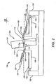
- the axisymmetric resonator is coupled to a baseplate 106 such that the axisymmetric counterbalancing plate 104 can freely vibrate against the axisymmetric central proof mass 102 with counterbalanced oscillatory rocking motion and results in a distinct differential rocking mode with substantially no momentum transfer to or net reaction on the baseplate 106.
- Electrostatic driving and sensing can be implemented with the drive and sense electrodes 120A, 120B (collectively referred to as electrodes 120) affixed to the baseplate 106 beneath the large planar surfaces of the counterbalancing plate 104. See FIG. 1 .
- the large surface area of the counterbalancing plate 104 is used to react with the driving and sensing electrodes 120.
- the extensive planar electrode 120 regions are formed on the baseplate 106 beneath the counterbalancing plate 104.
- the counterbalancing plate 104 structure extends toward the central proof mass 102 beyond the attachment points 122 of flexures 108 to the counterbalancing plate 104 as shown in FIG. 1 to maximize the useful area.
- the gap between the proof mass 102 and the counterbalancing plate 104 is reduced and the counterbalancing plate 104 obtains a more plate-like configuration.
- embodiments of the present invention can also incorporate integral vibration isolation to the baseplate 106 to further improve differential and common rocking mode frequency separation and vibration isolation of the resonator 124.
- a mounting frame 128 is attached to the baseplate 106 through one or more isolation flexures 130.
- the baseplate 106 isolation of the resonator 124 is primarily considered with respect to the mounting frame 128 with the baseplate 106 serving as an additional isolating element.
- the baseplate 106 isolation flexure 130 width and/or length can be set to attenuate axial or rocking vibrations above 500 Hz from the case. In the embodiment shown in FIGS.
Landscapes
- Physics & Mathematics (AREA)
- Engineering & Computer Science (AREA)
- General Physics & Mathematics (AREA)
- Radar, Positioning & Navigation (AREA)
- Remote Sensing (AREA)
- Gyroscopes (AREA)
Claims (21)
- Gyroscope à résonateur, comprenant :un résonateur isolé (124) comportant :une masse étalon (102) ;une plaque d'équilibrage (104) ayant une région plane étendue ; etun ou plusieurs éléments de flexion (108) reliant entre elles la masse étalon et la plaque d'équilibrage, ladite plaque d'équilibrage (104) s'étendant vers ladite masse étalon (102), au-delà de points de raccordement (122) desdits éléments de flexion à ladite plaque d'équilibrage (104) afin d'obtenir une configuration ayant davantage l'aspect d'une plaque ;une plaque de base (106) fixée au résonateur (124) par les un ou plusieurs éléments de flexion (108) ; etdes électrodes d'attaque et de détection (120) fixées à la plaque de base (106) à proximité de la région plane étendue de la plaque d'équilibrage (104) pour exciter le résonateur et détecter le mouvement du gyroscope ;dans lequel le résonateur isolé ne transfère sensiblement aucune quantité de mouvement nette à la plaque de base lorsque le résonateur est excité.
- Gyroscope à résonateur selon la revendication 1, dans lequel la masse étalon (102) et la plaque d'équilibrage (104) ont chacune, par rapport à un axe, un centre de masse et une symétrie inertielle transversale qui coïncident sensiblement l'un avec l'autre, et la masse étalon (102) et la plaque d'équilibrage (104) forment ensemble deux modes de vibration différentielle en oscillation transversalement à l'axe avec des fréquences sensiblement égales.
- Gyroscope à résonateur selon la revendication 1 ou 2, dans lequel les électrodes de détection (120) sont disposées suivant la périphérie de la plaque d'équilibrage (104).
- Gyroscope à résonateur selon l'une quelconque des revendications précédentes, comprenant en outre un châssis de montage (128) fixé à la plaque de base (106) par l'intermédiaire d'au moins un élément de flexion d'isolation (130).
- Gyroscope à résonateur selon l'une quelconque des revendications précédentes, dans lequel la plaque de base (106) est rigide.
- Gyroscope à résonateur selon l'une quelconque des revendications précédentes, dans lequel la plaque de base (106) est souple (61).
- Gyroscope à résonateur selon l'une quelconque des revendications précédentes, dans lequel la plaque d'équilibrage a une inertie d'oscillation sensiblement comparable à celle de la masse étalon (102).
- Gyroscope à résonateur selon l'une quelconque des revendications précédentes, dans lequel les un ou plusieurs éléments de flexion (108) font partie intégrante de la plaque d'équilibrage (104).
- Gyroscope à résonateur selon l'une quelconque des revendications précédentes, dans lequel la masse étalon (102), la plaque d'équilibrage (104) et la plaque de base (106) sont usinées dans du silicium.
- Gyroscope à résonateur selon l'une quelconque des revendications précédentes, dans lequel chacun des un ou plusieurs éléments de flexion (108) est un élément de flexion à fléau fixé à la masse étalon (102) par une première extrémité et à la plaque d'équilibrage (104) par une seconde extrémité.
- Gyroscope à résonateur selon la revendication 10, dans lequel chaque élément de flexion à fléau (108) est fixé à la plaque de base (106) de façon excentrée et plus près de la masse étalon que d'un point de fixation à la plaque d'équilibrage (104).
- Gyroscope à résonateur selon l'une quelconque des revendications précédentes, dans lequel la masse étalon (102) comprend une partie verticale (116) et une partie de plaque centrale (118).
- Gyroscope à résonateur selon la revendication 12, dans lequel les un ou plusieurs éléments de flexion (108) sont solidaires de la partie de plaque centrale.
- Gyroscope à résonateur selon la revendication 12, dans lequel la partie de plaque centrale (118), les un ou plusieurs éléments de flexion (108) et la plaque d'équilibrage (104) sont produits par gravure traversante d'une tranche de silicium polie avec précision.
- Gyroscope à résonateur selon la revendication 12, dans lequel la partie verticale (116) est un élément séparé collé à la partie de plaque centrale (118).
- Gyroscope à résonateur selon la revendication 15, dans lequel l'élément séparé comprend un saphir.
- Procédé de production d'un gyroscope à résonateur, comprenant les étapes consistant à fournir un résonateur isolé (124) comportant :une masse étalon (102) ;une plaque d'équilibrage (104) ayant une région plane étendue ; etun ou plusieurs éléments de flexion (108) reliant entre elles la masse étalon (102) et la plaque d'équilibrage (104),ladite plaque d'équilibrage (104) s'étendant vers ladite masse étalon (102), au-delà de points de raccordement (122) desdits éléments de flexion à ladite plaque d'équilibrage (104) afin d'obtenir une configuration ayant davantage l'aspect d'une plaqué ;la fixation d'électrodes d'attaque et de détection (120) à une plaque de base (106) ; etla fixation du résonateur à la plaque de base (106) au moyen des un ou plusieurs éléments de flexion (108) de façon à ce que les électrodes d'attaque et de détection (120) soient disposées à proximité de la région plane étendue de la plaque d'équilibrage (104).
- Procédé selon la revendication 17, dans lequel les un ou plusieurs éléments de flexion (108) sont produits de façon solidaire de la plaque d'équilibrage (104).
- Procédé selon la revendication 17, dans lequel les étapes de production et de fixation consistent à usiner la masse étalon (102), la plaque d'équilibrage (104) et la plaque de base (106) dans du silicium.
- Procédé selon la revendication 17, dans lequel une partie de plaque centrale (118) de la masse étalon (102), un ou plusieurs éléments de flexion et la plaque d'équilibrage sont produits par gravure traversante d'une tranche de silicium polie avec précision.
- Procédé selon la revendication 17, dans lequel une partie verticale (116) de la masse étalon (102) est un élément séparé de la partie de plaque centrale (118) et l'étape de production de la masse étalon consiste à coller la partie verticale à la partie de plaque centrale.
Applications Claiming Priority (2)
| Application Number | Priority Date | Filing Date | Title |
|---|---|---|---|
| US370953 | 2003-02-20 | ||
| US10/370,953 US7017410B2 (en) | 2001-08-10 | 2003-02-20 | Isolated resonator gyroscope with a drive and sense plate |
Publications (3)
| Publication Number | Publication Date |
|---|---|
| EP1450131A2 EP1450131A2 (fr) | 2004-08-25 |
| EP1450131A3 EP1450131A3 (fr) | 2005-03-16 |
| EP1450131B1 true EP1450131B1 (fr) | 2011-04-06 |
Family
ID=32736451
Family Applications (1)
| Application Number | Title | Priority Date | Filing Date |
|---|---|---|---|
| EP04003915A Expired - Lifetime EP1450131B1 (fr) | 2003-02-20 | 2004-02-20 | Gyroscope à vibration isolé avec une plaque d'entraînement et de détection |
Country Status (4)
| Country | Link |
|---|---|
| US (2) | US7017410B2 (fr) |
| EP (1) | EP1450131B1 (fr) |
| JP (1) | JP4620364B2 (fr) |
| DE (1) | DE602004032075D1 (fr) |
Families Citing this family (30)
| Publication number | Priority date | Publication date | Assignee | Title |
|---|---|---|---|---|
| US6915215B2 (en) * | 2002-06-25 | 2005-07-05 | The Boeing Company | Integrated low power digital gyro control electronics |
| US7691723B2 (en) * | 2005-01-07 | 2010-04-06 | Honeywell International Inc. | Bonding system having stress control |
| US7818871B2 (en) | 2006-07-25 | 2010-10-26 | California Institute Of Technology | Disc resonator gyroscope fabrication process requiring no bonding alignment |
| JP4851555B2 (ja) * | 2008-05-13 | 2012-01-11 | 株式会社デンソー | 力学量センサおよびその製造方法 |
| US8039912B2 (en) * | 2008-06-25 | 2011-10-18 | Honeywell International Inc. | Systems and methods for reduced stress anchors |
| US8450913B1 (en) * | 2011-03-31 | 2013-05-28 | Georgia Tech Research Corporation | Tunable Piezoelectric MEMS Resonators suitable for real-time clock applications |
| US8960003B2 (en) * | 2011-09-16 | 2015-02-24 | Taiwan Semiconductor Manufacturing Company, Ltd. | Motion sensor device and methods for forming the same |
| EP2573516B1 (fr) * | 2011-09-21 | 2013-11-20 | Tronics Microsystems S.A. | Un gyroscope micro-electromécanique |
| US8650955B2 (en) * | 2012-01-18 | 2014-02-18 | The United States Of America As Represented By The Secretary Of The Navy | Time domain switched gyroscope |
| CN102661744B (zh) * | 2012-05-31 | 2014-12-17 | 东南大学 | 硅基双平衡环动调陀螺转子体结构与加工方法 |
| KR101388814B1 (ko) | 2012-09-11 | 2014-04-23 | 삼성전기주식회사 | 각속도 센서 |
| US10273147B2 (en) | 2013-07-08 | 2019-04-30 | Motion Engine Inc. | MEMS components and method of wafer-level manufacturing thereof |
| JP6339669B2 (ja) | 2013-07-08 | 2018-06-06 | モーション・エンジン・インコーポレーテッド | Memsデバイスおよび製造する方法 |
| KR101531093B1 (ko) * | 2013-07-31 | 2015-06-23 | 삼성전기주식회사 | 가속도 센서 및 각속도 센서 |
| WO2015013828A1 (fr) | 2013-08-02 | 2015-02-05 | Motion Engine Inc. | Capteur de mouvement à système microélectromécanique (mems) et procédé de fabrication |
| US20150168146A1 (en) * | 2013-12-13 | 2015-06-18 | Sensors In Motion | Planar accelerometer with internal radial sensing and actuation |
| EP3092499B1 (fr) * | 2013-12-30 | 2018-10-31 | Robert Bosch GmbH | Capteurs inertiels robustes |
| WO2015103688A1 (fr) | 2014-01-09 | 2015-07-16 | Motion Engine Inc. | Système mems intégré |
| US20170030788A1 (en) | 2014-04-10 | 2017-02-02 | Motion Engine Inc. | Mems pressure sensor |
| WO2015184531A1 (fr) | 2014-06-02 | 2015-12-10 | Motion Engine Inc. | Capteur de mouvement mems à plusieurs masses |
| CN104197919B (zh) * | 2014-08-08 | 2017-06-13 | 上海交通大学 | 上下贯通支撑的玻璃金属半球谐振微陀螺 |
| US11287486B2 (en) | 2014-12-09 | 2022-03-29 | Motion Engine, Inc. | 3D MEMS magnetometer and associated methods |
| CA3220839A1 (fr) | 2015-01-15 | 2016-07-21 | Motion Engine Inc. | Dispositif mems 3d a cavite hermetique |
| US10551190B1 (en) | 2015-10-30 | 2020-02-04 | Garmin International, Inc. | Multi Coriolis structured gyroscope |
| US10794700B1 (en) | 2015-10-30 | 2020-10-06 | Garmin International, Inc. | Stress isolation of resonating gyroscopes |
| US10278281B1 (en) | 2015-10-30 | 2019-04-30 | Garmin International, Inc. | MEMS stress isolation and stabilization system |
| US10352960B1 (en) | 2015-10-30 | 2019-07-16 | Garmin International, Inc. | Free mass MEMS accelerometer |
| US10126128B2 (en) | 2016-05-26 | 2018-11-13 | Nxp Usa, Inc. | Angular rate sensor |
| JP2020030067A (ja) * | 2018-08-21 | 2020-02-27 | セイコーエプソン株式会社 | 物理量センサー、センサーデバイス、電子機器、および移動体 |
| CN109813853A (zh) * | 2019-03-16 | 2019-05-28 | 中国民用航空飞行学院 | 一种便携式泡沫灭火剂稳定性能检测仪 |
Family Cites Families (29)
| Publication number | Priority date | Publication date | Assignee | Title |
|---|---|---|---|---|
| US392650A (en) | 1888-11-13 | watrous | ||
| EP0461761B1 (fr) | 1990-05-18 | 1994-06-22 | British Aerospace Public Limited Company | Senseurs inertiels |
| US5203208A (en) * | 1991-04-29 | 1993-04-20 | The Charles Stark Draper Laboratory | Symmetrical micromechanical gyroscope |
| US5665915A (en) | 1992-03-25 | 1997-09-09 | Fuji Electric Co., Ltd. | Semiconductor capacitive acceleration sensor |
| US5646346A (en) | 1994-11-10 | 1997-07-08 | Okada; Kazuhiro | Multi-axial angular velocity sensor |
| US6044705A (en) | 1993-10-18 | 2000-04-04 | Xros, Inc. | Micromachined members coupled for relative rotation by torsion bars |
| US5488862A (en) * | 1993-10-18 | 1996-02-06 | Armand P. Neukermans | Monolithic silicon rate-gyro with integrated sensors |
| DE4442033C2 (de) | 1994-11-25 | 1997-12-18 | Bosch Gmbh Robert | Drehratensensor |
| JP3585980B2 (ja) * | 1995-02-21 | 2004-11-10 | 株式会社ワコー | 角速度センサ |
| JPH08285608A (ja) * | 1995-04-14 | 1996-11-01 | Miyota Kk | 角速度センサ |
| CA2217766A1 (fr) | 1995-05-31 | 1996-12-05 | Litef Gmbh | Capteur micromecanique de vitesse de rotation |
| DE19530007C2 (de) | 1995-08-16 | 1998-11-26 | Bosch Gmbh Robert | Drehratensensor |
| US5756895A (en) | 1995-09-01 | 1998-05-26 | Hughes Aircraft Company | Tunneling-based rate gyros with simple drive and sense axis coupling |
| KR0171009B1 (ko) | 1995-12-07 | 1999-05-01 | 양승택 | 원판 진동형 마이크로 자이로스코프 및 그의 제조방법 |
| US5894090A (en) | 1996-05-31 | 1999-04-13 | California Institute Of Technology | Silicon bulk micromachined, symmetric, degenerate vibratorygyroscope, accelerometer and sensor and method for using the same |
| DE19641284C1 (de) | 1996-10-07 | 1998-05-20 | Inst Mikro Und Informationstec | Drehratensensor mit entkoppelten orthogonalen Primär- und Sekundärschwingungen |
| JP3865854B2 (ja) * | 1997-02-12 | 2007-01-10 | 株式会社ワコー | 振動子を用いた角速度センサ |
| US6151964A (en) | 1998-05-25 | 2000-11-28 | Citizen Watch Co., Ltd. | Angular velocity sensing device |
| US5920012A (en) | 1998-06-16 | 1999-07-06 | Boeing North American | Micromechanical inertial sensor |
| JP3106395B2 (ja) | 1998-07-10 | 2000-11-06 | 株式会社村田製作所 | 角速度センサ |
| GB9817347D0 (en) * | 1998-08-11 | 1998-10-07 | British Aerospace | An angular rate sensor |
| US6009751A (en) | 1998-10-27 | 2000-01-04 | Ljung; Bo Hans Gunnar | Coriolis gyro sensor |
| US6164134A (en) | 1999-01-29 | 2000-12-26 | Hughes Electronics Corporation | Balanced vibratory gyroscope and amplitude control for same |
| US6481285B1 (en) | 1999-04-21 | 2002-11-19 | Andrei M. Shkel | Micro-machined angle-measuring gyroscope |
| US6289733B1 (en) | 1999-05-12 | 2001-09-18 | Hughes Electronics Corporation | Planar vibratory gyroscopes |
| US6367786B1 (en) | 1999-06-07 | 2002-04-09 | California Institute Of Technology | Micromachined double resonator |
| US6245590B1 (en) * | 1999-08-05 | 2001-06-12 | Microvision Inc. | Frequency tunable resonant scanner and method of making |
| JP2002350138A (ja) * | 2001-05-28 | 2002-12-04 | Wacoh Corp | 加速度と角速度との双方を検出する装置 |
| US6629460B2 (en) * | 2001-08-10 | 2003-10-07 | The Boeing Company | Isolated resonator gyroscope |
-
2003
- 2003-02-20 US US10/370,953 patent/US7017410B2/en not_active Expired - Lifetime
-
2004
- 2004-02-20 JP JP2004044947A patent/JP4620364B2/ja not_active Expired - Fee Related
- 2004-02-20 EP EP04003915A patent/EP1450131B1/fr not_active Expired - Lifetime
- 2004-02-20 DE DE602004032075T patent/DE602004032075D1/de not_active Expired - Lifetime
-
2005
- 2005-02-04 US US11/051,884 patent/US7093486B2/en not_active Expired - Lifetime
Also Published As
| Publication number | Publication date |
|---|---|
| US20060070440A1 (en) | 2006-04-06 |
| US7093486B2 (en) | 2006-08-22 |
| JP2004251909A (ja) | 2004-09-09 |
| DE602004032075D1 (de) | 2011-05-19 |
| EP1450131A3 (fr) | 2005-03-16 |
| EP1450131A2 (fr) | 2004-08-25 |
| US20030150267A1 (en) | 2003-08-14 |
| US7017410B2 (en) | 2006-03-28 |
| JP4620364B2 (ja) | 2011-01-26 |
Similar Documents
| Publication | Publication Date | Title |
|---|---|---|
| US7093486B2 (en) | Isolated resonator gyroscope with a drive and sense plate | |
| EP1415127B1 (fr) | Gyroscope a resonateur isole | |
| EP0902875B1 (fr) | Capteur de gyroscope vibrant, symetrique, fabrique par micro-usinage de silicium | |
| US7493814B2 (en) | Vibratory gyroscope with parasitic mode damping | |
| JP3834397B2 (ja) | レートセンサ | |
| US7624494B2 (en) | Method of fabricating a mesoscaled resonator | |
| US7347095B2 (en) | Integral resonator gyroscope | |
| US7793541B2 (en) | Planar resonator gyroscope central die attachment | |
| US7210347B2 (en) | Micromachined inertial sensor for measuring rotational movements | |
| US6990863B2 (en) | Isolated resonator gyroscope with isolation trimming using a secondary element | |
| US8418554B2 (en) | Gyroscope packaging assembly | |
| US6823734B1 (en) | Electrostatic spring softening in redundant degree of freedom resonators | |
| US6955084B2 (en) | Isolated resonator gyroscope with compact flexures | |
| JP4698221B2 (ja) | 内部径方向検知およびアクチュエーションを備える分離型平面ジャイロスコープ | |
| Challoner et al. | Isolated resonator gyroscope with a drive and sense plate | |
| Shcheglov et al. | Method of producing an integral resonator sensor and case |
Legal Events
| Date | Code | Title | Description |
|---|---|---|---|
| PUAI | Public reference made under article 153(3) epc to a published international application that has entered the european phase |
Free format text: ORIGINAL CODE: 0009012 |
|
| AK | Designated contracting states |
Kind code of ref document: A2 Designated state(s): AT BE BG CH CY CZ DE DK EE ES FI FR GB GR HU IE IT LI LU MC NL PT RO SE SI SK TR |
|
| AX | Request for extension of the european patent |
Extension state: AL LT LV MK |
|
| PUAL | Search report despatched |
Free format text: ORIGINAL CODE: 0009013 |
|
| AK | Designated contracting states |
Kind code of ref document: A3 Designated state(s): AT BE BG CH CY CZ DE DK EE ES FI FR GB GR HU IE IT LI LU MC NL PT RO SE SI SK TR |
|
| AX | Request for extension of the european patent |
Extension state: AL LT LV MK |
|
| 17P | Request for examination filed |
Effective date: 20050817 |
|
| AKX | Designation fees paid |
Designated state(s): DE FR GB |
|
| 17Q | First examination report despatched |
Effective date: 20061123 |
|
| GRAP | Despatch of communication of intention to grant a patent |
Free format text: ORIGINAL CODE: EPIDOSNIGR1 |
|
| GRAS | Grant fee paid |
Free format text: ORIGINAL CODE: EPIDOSNIGR3 |
|
| GRAA | (expected) grant |
Free format text: ORIGINAL CODE: 0009210 |
|
| AK | Designated contracting states |
Kind code of ref document: B1 Designated state(s): DE FR GB |
|
| REG | Reference to a national code |
Ref country code: GB Ref legal event code: FG4D |
|
| REF | Corresponds to: |
Ref document number: 602004032075 Country of ref document: DE Date of ref document: 20110519 Kind code of ref document: P |
|
| REG | Reference to a national code |
Ref country code: DE Ref legal event code: R096 Ref document number: 602004032075 Country of ref document: DE Effective date: 20110519 |
|
| PLBE | No opposition filed within time limit |
Free format text: ORIGINAL CODE: 0009261 |
|
| STAA | Information on the status of an ep patent application or granted ep patent |
Free format text: STATUS: NO OPPOSITION FILED WITHIN TIME LIMIT |
|
| 26N | No opposition filed |
Effective date: 20120110 |
|
| REG | Reference to a national code |
Ref country code: DE Ref legal event code: R097 Ref document number: 602004032075 Country of ref document: DE Effective date: 20120110 |
|
| REG | Reference to a national code |
Ref country code: FR Ref legal event code: PLFP Year of fee payment: 13 |
|
| REG | Reference to a national code |
Ref country code: FR Ref legal event code: PLFP Year of fee payment: 14 |
|
| REG | Reference to a national code |
Ref country code: FR Ref legal event code: PLFP Year of fee payment: 15 |
|
| PGFP | Annual fee paid to national office [announced via postgrant information from national office to epo] |
Ref country code: FR Payment date: 20210223 Year of fee payment: 18 |
|
| PGFP | Annual fee paid to national office [announced via postgrant information from national office to epo] |
Ref country code: GB Payment date: 20210225 Year of fee payment: 18 Ref country code: DE Payment date: 20210225 Year of fee payment: 18 |
|
| REG | Reference to a national code |
Ref country code: DE Ref legal event code: R119 Ref document number: 602004032075 Country of ref document: DE |
|
| GBPC | Gb: european patent ceased through non-payment of renewal fee |
Effective date: 20220220 |
|
| PG25 | Lapsed in a contracting state [announced via postgrant information from national office to epo] |
Ref country code: FR Free format text: LAPSE BECAUSE OF NON-PAYMENT OF DUE FEES Effective date: 20220228 |
|
| PG25 | Lapsed in a contracting state [announced via postgrant information from national office to epo] |
Ref country code: GB Free format text: LAPSE BECAUSE OF NON-PAYMENT OF DUE FEES Effective date: 20220220 Ref country code: DE Free format text: LAPSE BECAUSE OF NON-PAYMENT OF DUE FEES Effective date: 20220901 |