EP1449043B1 - Steuerbarer transformer - Google Patents
Steuerbarer transformer Download PDFInfo
- Publication number
- EP1449043B1 EP1449043B1 EP02803575A EP02803575A EP1449043B1 EP 1449043 B1 EP1449043 B1 EP 1449043B1 EP 02803575 A EP02803575 A EP 02803575A EP 02803575 A EP02803575 A EP 02803575A EP 1449043 B1 EP1449043 B1 EP 1449043B1
- Authority
- EP
- European Patent Office
- Prior art keywords
- winding
- transformer
- voltage
- control
- primary
- Prior art date
- Legal status (The legal status is an assumption and is not a legal conclusion. Google has not performed a legal analysis and makes no representation as to the accuracy of the status listed.)
- Expired - Lifetime
Links
- 238000004804 winding Methods 0.000 claims abstract description 341
- 239000000696 magnetic material Substances 0.000 claims abstract description 12
- 230000008859 change Effects 0.000 claims description 22
- 230000000694 effects Effects 0.000 claims description 18
- 238000000034 method Methods 0.000 claims description 17
- 230000004913 activation Effects 0.000 claims description 7
- 238000006243 chemical reaction Methods 0.000 claims description 7
- 230000003213 activating effect Effects 0.000 claims description 3
- 238000012546 transfer Methods 0.000 claims description 3
- 230000009466 transformation Effects 0.000 claims description 3
- 230000004044 response Effects 0.000 claims description 2
- 239000011162 core material Substances 0.000 description 45
- 239000004020 conductor Substances 0.000 description 31
- 230000004907 flux Effects 0.000 description 25
- 239000000463 material Substances 0.000 description 11
- 230000001276 controlling effect Effects 0.000 description 6
- 238000013461 design Methods 0.000 description 4
- 238000010586 diagram Methods 0.000 description 4
- 230000001965 increasing effect Effects 0.000 description 4
- 230000006698 induction Effects 0.000 description 4
- 239000000843 powder Substances 0.000 description 4
- 230000007423 decrease Effects 0.000 description 3
- 230000035699 permeability Effects 0.000 description 3
- 229910000859 α-Fe Inorganic materials 0.000 description 3
- 230000009849 deactivation Effects 0.000 description 2
- 230000006870 function Effects 0.000 description 2
- 230000014509 gene expression Effects 0.000 description 2
- 239000011810 insulating material Substances 0.000 description 2
- 230000009467 reduction Effects 0.000 description 2
- 230000001105 regulatory effect Effects 0.000 description 2
- 238000011160 research Methods 0.000 description 2
- 230000009471 action Effects 0.000 description 1
- 230000000903 blocking effect Effects 0.000 description 1
- 230000002301 combined effect Effects 0.000 description 1
- 230000001419 dependent effect Effects 0.000 description 1
- 238000011161 development Methods 0.000 description 1
- 230000002349 favourable effect Effects 0.000 description 1
- 238000001914 filtration Methods 0.000 description 1
- 230000001939 inductive effect Effects 0.000 description 1
- 238000004519 manufacturing process Methods 0.000 description 1
- 230000010363 phase shift Effects 0.000 description 1
- 238000012360 testing method Methods 0.000 description 1
- 230000001052 transient effect Effects 0.000 description 1
Images


















Classifications
-
- H—ELECTRICITY
- H01—ELECTRIC ELEMENTS
- H01F—MAGNETS; INDUCTANCES; TRANSFORMERS; SELECTION OF MATERIALS FOR THEIR MAGNETIC PROPERTIES
- H01F27/00—Details of transformers or inductances, in general
- H01F27/28—Coils; Windings; Conductive connections
- H01F27/30—Fastening or clamping coils, windings, or parts thereof together; Fastening or mounting coils or windings on core, casing, or other support
-
- G—PHYSICS
- G05—CONTROLLING; REGULATING
- G05F—SYSTEMS FOR REGULATING ELECTRIC OR MAGNETIC VARIABLES
- G05F1/00—Automatic systems in which deviations of an electric quantity from one or more predetermined values are detected at the output of the system and fed back to a device within the system to restore the detected quantity to its predetermined value or values, i.e. retroactive systems
- G05F1/10—Regulating voltage or current
- G05F1/12—Regulating voltage or current wherein the variable actually regulated by the final control device is AC
- G05F1/32—Regulating voltage or current wherein the variable actually regulated by the final control device is AC using magnetic devices having a controllable degree of saturation as final control devices
-
- H—ELECTRICITY
- H01—ELECTRIC ELEMENTS
- H01F—MAGNETS; INDUCTANCES; TRANSFORMERS; SELECTION OF MATERIALS FOR THEIR MAGNETIC PROPERTIES
- H01F27/00—Details of transformers or inductances, in general
- H01F27/24—Magnetic cores
Definitions
- the present invention relates to a method for controllable conversion of a primary alternating current/voltage to a secondary alternating current/voltage by use of a controllable transformer device comprising a body of a magnetic material, a primary winding wound round the body about a first axis, a secondary winding wound round the body about a second axis at right angles to the first axis, and a control winding wound around the body about a third axis coincident with the second axis, comprising:
- the transformer device is preferably designed as a hollow magnetisable core with an internal winding compartment for internal windings and an external winding compartment for external windings.
- it comprises 3 windings, a primary winding in the external winding compartment with associated control winding in the internal winding compartment, and a secondary winding in the internal winding compartment.
- the windings in the external winding compartment and the windings in the internal winding compartment are aligned at right angles (perpendicular) to each other in the compartment, thereby creating magnetic fields that are orthogonal.
- the internal winding compartment may of course house the primary winding and the external winding compartment may house the secondary winding and the control winding.
- the frequency converter is specially, but not in a limiting manner, intended for use in the MVA range.
- the invention is a further development of the device set forth in PCT/NO01/00217.
- primary winding and “secondary winding” are used to design a winding where energy is input (primary) and a winding which is meant for connection to a load (secundary) as is usual in transformators.
- primary and the propeller windings are wound round orthogonal axes.
- control winding denotes a winding which controls the tranformer's tranformation ratio.
- a transformer comprising orthogonal windings is previously known from US patent 4,210,859, Meretsky et al. of April 18, 1978.
- the known solution manifests several disadvantages.
- the main aspects of the invention will be described below based on the prior art described in said publication.
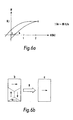
- 6h illustrates the linear part of the magnetisation curve for a standard commercial core plate.
- a laminar material is used where the magnetisation curve is the same for all directions in the plate. This involves the use of nondirectional plate without this being considered as limiting for the application, since for some applications it may be advantageous to have a directionally oriented plate.
- US patent 4,210,859 illustrates a connection diagram for a variable transformer solution with 4 windings: a primary main winding, a secondary main winding arranged at right angles to the primary winding and two control windings, one for each main winding.
- the mode of operation is such that a variable DC current in both control windings will result in a transfer of AC voltage from the primary to the secondary winding.
- a transformer of this kind cannot be considered a realistic option, particularly if the area of application is outside the mA range, because a DC current in the control windings will rotate the domains in the magnetic material in an unfavourable direction for connection in one half cycle of the primary voltage, causing harmonics in the secondary voltage. This phenomenon, which has been extensively studied by the inventors is not taken into consideration in US patent 4,210,859.
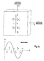
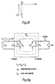
- figs. 6c to 6d illustrate said rotation of the domains.
- Vp represents a voltage on the primary winding and Vs a voltage on the secondary winding.
- Vp denotes the winding axis of the primary winding and Vs the winding axis of the startery winding. Flux produced or linked by the primary winding will then have the direction of Vp while flux produced or linked by the depoty winding will have the direction of Vs.
- the domains are aligned according to the primary voltage Vp and their magnetisation B will vary roughly as shown in the figure.
- the magnetic field H produced by this priomary winding will vary from positive to zero and from zero to a negative value.
- phase shift of the magnetisation in relation to the primary voltage is not included here in order to simplify the illustration, (the magnetisation current lags 90 degrees behind the voltage).
- a control field Bkdc is introduced by activating the control winding and exciting it with DC.
- the control field is added to the primary field Bkvp, establishing a magnetisation Bkr as illustrated. Since a constant field is added to a sinusoidal field, the sum will change sinusoidally in direction and sinusoidally in field strength.
- the simplyfied diagram 6d illustrates that we obtain a change in domain alignment direction that becomes a product of two sinus functions. Both direction and field strength for the resulting field are changed sinusoidally.
- the induced voltage Vs in the secondary winding will be given by two effects. The fact that the domains change direction will give an induction and the fact that the domains change in size will give an additional induction.
- Bkr is the sum of the magnetisation from the primary side Bkvp and the magnetisation Bkdc from the control current.
- V s K 2 ⁇ cos ( 2 ⁇ ⁇ ⁇ t )
- control winding on the primary side is transformatively connected to the primary winding and will be under voltage from the primary side, thereby making it very difficult to regulate without extensive filtering.
- US patent 4,210,859 also discloses a transformer connection (fig. 18) where windings with right-angled axes are interconnected in series two by two.
- the publication states that the core's utilisation can be increased by using such a connection. This is not correct, however, since the magnetic fields for the windings are summed vectorially and the described effect will not be achieved.
- the magnetisation is controlled by means of a pulsed DC or pulsed AC control current in a secondary control winding orthogonal to the primary control winding.
- a pulsed DC or pulsed AC control current in a secondary control winding orthogonal to the primary control winding.
- a magnetisation current is established in the control winding that conforms to the magnetisation current from the primary winding in amplitude in order to enable a transformative connection to be established between the primary and secondary winding that does not produce undesirable frequencies in the secondary voltage. Without this magnetisation it is not possible to activate transformative connection to the secondary winding. There will be some degree of connection on account of the winding's extension in the compartment, which will provide an induced component and also a second induced component due to nonlinearities in the material, but this connection will not be capable of providing the desired transformative effect.
- the control winding Since the sum of the magnetisation currents is the cause of the transformer effect, we want to keep the controlled part of the magnetisation current in the secondary circuit unaffected by load changes in the secondary circuit, i.e. the current in the control winding is kept constant during a load change.
- a suitable inductance in the control winding e.g. by means of the prior art from PCT/NO01/00217, the current in the control winding will be perceived as constant during domain changes caused by load changes in the secondary circuit this is because an inductance will "smooth" the changes in the current.
- the control winding will also be under induction from the primary voltage Vp.
- the control winding is also directly transformatively connected to the secondary winding and a control voltage in the control winding will be transformed to the secondary winding.
- current in the secondary winding will now influence the domain distortion and the phase ratio between primary and secondary winding.
- all currents in the system must be monitored and the control winding must be excited so as to compensate for domain changes established by the secondary winding.
- an inductance is introduced in the control circuit that causes an approximately constant current in the control winding and gives a sufficient drop in voltage between the control winding and the secondary winding.
- the transformed voltage in the secondary winding from the primary side and the transformed voltage in the secondary winding from the control winding will be in phase or in antiphase, since we have basically used a control voltage that should be in phase with the primary voltage in order to obtain a directionally constant domain change. It is also important to be aware that the core is reset at every zero passage in the voltages. Thus by removing the control current the magnetisation angle between the windings will decrease due to the fact that the secondary current decreases and after a few periods we are back to minimal connection.
- the transformer according to the invention comprises only one control winding located in the winding compartment together with the secondary winding.
- a control winding in the primary winding compartment is not necessary since the primary winding will rotate the domains in its' direction and also rotate any domains established from a current in the secondary winding to the same direction.
- the domains In order to obtain transformative connection between the orthogonal windings, the domains must be rotated as mentioned above in order to efficiently produce a magnetisation that is in a favourable direction for transformative connection between the primary and the secondary winding. The best that can be achieved is a rotation of 45 degrees for the domains. (From a different point of view, we "twist" the secondary winding relative to the primary winding in such a manner that some of the field from the primary winding passes through the secondary winding.)
- an (AC) alternating voltage is used on the control winding, which as previously mentioned is located in the same winding compartment as the secondary winding.
- AC AC
- this current will reinforce the connection with the primary side by the domains being helped in the right direction by the field from the secondary current and the field from the control current.
- control voltage in the transformer according to the invention will be in phase with or phase shifted 180 degrees relative to the voltage on the primary side in order to obtain a distortion-free transformation.
- the current in the control winding can be regulated by a system that monitors the primary and the secondary current/voltage as well as the control current, thus enabling the connection and the electrical angle between the windings to be controlled by means of the alignment of the domains.
- the values of current and voltage in the primary, secondary and control winding will give a clear indication of the state of the domains (rotation and magnetisation) and thus these parameters together with reference values can be used for controlling the transformer's operation and adapt it to different operation conditions.
- the transformer according to the invention may also advantageously be employed as a controlled rectifier or frequency converter.
- two methods may be employed. These will be described in detail with reference to the drawings.
- the first method comprises:
- the transformative connection between the primary and the secondary side will be as for an ordinary transformer as long as the transformation occurs in the linear region of the magnetisation curve and as long as the directional dependence of the permeability in the plate is approximately symmetrical and the control current is in phase with the primary voltage and of such a strength that the direction of the domains is not changed during the primary voltage sequence.
- the invention relates to a new device, since the primary and the secondary windings do not have parallel, but right-angled winding axes, and a control of the domain state is included.
- Figure 1a illustrates a device comprising a body 1 of a magnetisable material that forms a closed magnetic circuit.
- This magnetisable body or core 1 may be annular in form or of another suitable shape.
- a first main winding 2 Around the body 1 is wound a first main winding 2, where the direction of the magnetic field H1 (corresponding to the direction of the flux density B1) that will be produced when the main winding 2 is excited will conform to the magnetic circuit.
- the main winding 2 resembles a winding in an ordinary transformer.
- the device comprises a second main winding 3, which is wound round the magnetisable body 1 in the same way as the main winding 2 and which will thereby provide a magnetic field extending substantially along the body 1 (i.e. parallel to H1, B1).
- the device comprises a third main winding 4, which in a preferred embodiment of the invention extends internally along the magnetic body 1.
- the magnetic field H2 (and thereby the flux density B2) that is created when the third main winding 4 is excited, will have a direction that is at right angles to the direction of the fields in the first and the second main winding (direction of H1, B1).
- the third main winding 4 constitutes a primary winding, the first main winding 2 the secondary winding and the second main winding 3 the control winding.
- the turns in the main winding follow the field direction from the control field and the turns in the control winding follow the field direction of the working field.
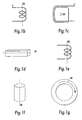
- Figures 1b-1g illustrate the definition of the axes and the direction of the various windings and the magnetic body.
- the secondary winding 2 will have an axis A2, the control winding 3 an axis A3 and the primary winding 4 an axis A4.
- the longitudinal direction will vary according to the shape. If the body is elongated, the longitudinal direction A1 will coincide with the body's longitudinal axis. If the magnetic body is square as illustrated in figure 1 a, it will be possible to define a longitudinal direction A1 for each leg of the square. Where the body is tubular, the longitudinal direction A1 will be the tube's axis, and for an annular body the longitudinal direction A1 will follow the circumference of the ring.
- the invention is based on the principle of aligning the domains in the core in the magnetisable body 1 in relation to a first magnetic field H2 by changing a second magnetic field H1 that is at right angles to the first.
- the field H2 may, for example, be defined as the working field and control the body's 1 domain direction (and thereby the behaviour of the working field H2) by means of the field H1 (hereinafter called control field H1).
- control field H1 hereinafter called control field H1
- the winding compartments are orthogonal with the result that the fields from the two windings are orthogonal and consequently there is no magnetic connection between the windings as long as no current is flowing in the control winding and the secondary winding.
- winding 4 is the primary winding and winding 2 the secondary winding while winding 3 is the control winding.
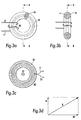
- Fig. 4 shows A1 as the flux area for secondary winding 2 and control winding 3 and this area may be called the area for the internal winding compartment iws, and A2 the flux area for the primary winding 4, or the area of the external winding compartment ews. Depending on the kind of conversion and connection required, it will be possible to give the areas equal or unequal dimensions.
- Fig. 4 is a diagram illustrating the transformer according to the invention where the windings are located with parallel and right-angled axes, and where the magnetisation direction is also represented.
- the domains and thereby the magnetisation must be aligned in such a manner that the angle between the domains and the windings that have to be influenced is different from 90 degrees.
- the best that can be achieved with connection between two orthogonal windings is to align the magnetisation in the body 1 by means of a control winding to 45 degrees. This means that with an equal number of turns on the primary and the secondary winding and the same flux area, a maximum of approximately 70% of the voltage can be transformed since sinus of 45 degrees is 0.707 and is the part of the flux area a winding rotated at 45 degrees relative to a source winding will cover.
- Fig. 5 illustrates the magnetisation curves for the entire material of the magnetisable body 1 and the domain change under the influence of the H1 field from the secondary winding 2.
- Fig. 6 illustrates the magnetisation curves for the entire material of the magnetisable body 1 and the domain change under the influence of the H2 field in the direction of the winding 4.
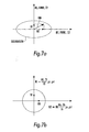
- Figs. 7a and 7b illustrate the flux densities B1 (where the field H1 is established by the secondary winding) and B2 (corresponding to the primary current).
- the ellipse illustrates the saturation limit for the B fields, i.e. when the B field reaches the limit, this will cause the material of the magnetisable body 1 to reach saturation.
- the design of the ellipse's axes will be given by the field length and the permeability of the two fields B1 (H1) and B2 (H2) in the core material of the magnetisable body 1.
- Figure 8 is a schematic illustration of a second embodiment of the invention.
- Fig. 9 illustrates the same embodiment of a magnetically influenced connector provided in a preferred embodiment of the transformer according to the invention, where fig. 9a illustrates the assembled connector and fig. 9b is an end view of the connector.
- Fig. 10 illustrates a section along line II in figure 9b.
- the magnetisable body 1 is co mposed inter alia of two parallel tubes 6 and 7 made of a magnetisable material.
- Magnetic field connectors 10, 11 are mounted at the ends of the respective tubes 6, 7 in order to interconnect the tubes fieldwise in a loop.
- the conductor 8 will be able to convey a load current I1 (fig. 9a).
- the tubes' 6, 7 length and diameter will be determined on the basis of the power and voltage that have to be connected.
- the number of turns N1 on the main winding 2 will be determined by the reverse blocking ability for voltage and the cross-sectional area for the magnitude of the working flux ⁇ 2.
- the number of turns N2 on the control winding 4 is determined by the conversion ratio required for the special transformer.
- winding 4 is arranged as primary winding and the winding 2 as control and secondary winding.
- Figure 11 illustrates an embodiment where the primary and the secondary main windings have been interchanged.
- the solution in fig. 11 differs from that illustrated in figs. 9a and 10 only by the fact that instead of a single insulated conductor 8, which is passed through the tubes 6 and 7, two separate oppositely directed conductors, so-called secondary conductors 8 and control conductors 8' are employed, in order thereby to achieve a voltage converter function in the magnetically influenced device according to the invention.
- the design basically resembles that illustrated in figs. 8, 9 and 10.
- the magnetisable body 1 comprises two parallel tubes 6 and 7.
- the magnetic field connectors 10, 11 are mounted at the end of the respective tubes 6, 7 in order to interconnect the tubes 6 and 7 fieldwise in a loop, thereby forming the magnetisable body 1.
- the conductor 8 and the conductor 8' are illustrated with only one pass through the tubes 6 and 7, it will be immediately apparent that both the conductor 8 and the conductor 8' will be able to be passed through the tubes 6 and 7 N1 and N1' number of times respectively.
- the tubes' 6 and 7 length and diameter will be determined on the basis of the power and voltage that have to be converted. For a transformer with a conversion ratio (N1:N1') equal to 10:1, in practice ten conductors will be used as conductors 8 and only one conductor 4.
- a magnetic field connector 10 and/or 11 is illustrated in figure 12.
- a magnetic field connector 10, 11 is illustrated composed of magnetically conducting material, wherein two preferably circular apertures 12 for the conductor 8 in the winding 2 (see, e.g., fig. 10) are machined out of the magnetic material in the connectors 10, 11. Furthermore, a gap 13 is provided which interrupts the magnetic field path of the conductor 8.
- End surface 14 is the connecting surface for the magnetic field H2 from the winding 4 consisting of conductor 9 and 9' (fig. 10).
- Fig. 13 illustrates a thin insulating film 15 which will be placed between the end surface of tubes 6 and 7 and the magnetic field connector 10, 11 in a preferred embodiment of the invention.
- FIGS 14 and 15 illustrate other alternative embodiments of the magnetic field connectors 10, 11.
- Figures 16-29 illustrate various embodiments of a core 16, which in the embodiment illustrated in figures 9, 10 and 11 forms the main part of the tubes 6 and 7, which preferably together with the magnetic field connectors 10 and 11 form the magnetisable body 1.
- Fig. 16 illustrates a cylindrical core part 16, which is divided lengthwise as illustrated and where one or more layers 17 of insulating material are placed between the two core halves 16,' 16".
- Fig. 17 illustrates a rectangular core part 16 and fig. 18 illustrates an embodiment of this core part 16 where it is divided in two with partial sections in the lateral surface.
- Fig. 18 illustrates an embodiment of this core part 16 where it is divided in two with partial sections in the lateral surface.
- one or more layers of insulating material 17 are placed between the core halves 16, 16'.
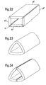
- a further variant is illustrated in figure 22 where the partial section is placed in each corner.
- Figs. 20, 21 and 22 illustrate a rectangular shape.
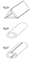
- Figures 23, 24 and 25 illustrate the same for a triangular shape.
- Figs. 26 and 27 illustrate an oval variant, and finally figures 28 and 29 illustrate a hexagonal shape.
- the hexagonal shape is composed of 6 equal surfaces 18 and in fig. 27 the hexagon consists of two parts 16' and 16".
- Reference numeral 17 refers to a thin insulating film.
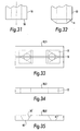
- FIGs 30 and 31 illustrate a magnetic field connector 10, 11 that can be used as a control field connector between the rectangular and square main cores 16 (illustrated in figures 10-11 and 20-22 respectively).
- This magnetic field connector comprises three parts 10', 10" and 19.
- Figure 31 illustrates an embodiment of a core part or main core 16 where the end surface 14 or the connecting surface for the control flux is at right angles to the axis of the core part 16.
- Figure 32 illustrates a second embodiment of the core part 16 where the connecting surface 14 for the control flux is at an angle ⁇ relative to the axis of the core part 16.
- Figures 33-39 illustrate various designs of the magnetic field connector 10, 11, which are based on the fact that the connecting surfaces 14' of the magnetic field connector 10, 11 are at the same angle as the end surfaces 14 to the core part 16.
- Fig. 33 illustrates a magnetic field connector 10, 11 in which different hole shapes 12 are indicated for the main winding 2 based on the shape of the core part 16 (round, triangular, etc.).
- the magnetic connector 10, 11 is flat. It is adapted for use with core parts 16 with right-angled end surfaces 14.
- an angle ⁇ ' is indicated to the magnetic field connector 10, 11, which is adapted to the angle ⁇ to the core part 16 (figure 32) with the result that the end surface 14 and the connecting surface 14' coincide.
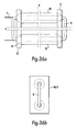
- FIG. 36a an embodiment of the invention is illustrated with an assembly of magnetic field connectors 10, 11 and core parts 16.
- Figure 36b illustrates the same embodiment viewed from the side.
- control winding will preferably follow the same winding compartment as the secondary winding.
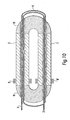
- Figures 37 and 38 are a sectional illustration and a view respectively illustrating a third embodiment of a magnetically influenced voltage connector device.
- the device comprises (see figure 37b) a magnetisable body 1 comprising an external tube 20 and an internal tube 21 (or core parts 16, 16') that are concentric and made of a magnetisable material with a gap 22 between the external tube's 20 inner wall and the internal tube's 21 outer wall.
- Magnetic field connectors 10, 11 between the tubes 20 and 21 are mounted at respective ends thereof (fig. 37a).
- a compartmentr 23 (fig. 37a) is placed in the gap 22 thus keeping the tubes 20, 21 concentric.
- a primary winding 4 composed of conductors 9 is wound round the internal tube 21 and is located in the said gap 22.
- the winding axis A2 for the primary winding 4 therefore coincides with the axis A1 of the tubes 20 and 21.
- This embodiment of the device can also be modified so that the tubes 20, 21 do not have a round cross section but a cross section that is square, rectangular, triangular, etc. We must define «winding compartment» better. It is not exactly a cavity in the core, since the windings are wound round the walls of the core.
- Figs. 39-41 illustrate different embodiments of the magnetic field connector 10, 11, which are specially adapted for the last-mentioned embodiment of the invention, i.e. that described in connection with figures 37 and 38.
- Figure 39a is a sectional view and figure 39b a view from above of a magnetic field connector 10, 11 with connecting surfaces 14' at an angle relative to the axis of the tubes 20, 21 (the core parts 16) and naturally the internal 21 and external 20 tubes will also be at the same angle to the connecting surfaces 14.
- Figs. 40 and 41 illustrate other variants of the magnetic field connector 10, 11 where the connecting surfaces 14' of the control field H2 (B2) are at right angles to the main axis of the core parts 16 (tubes 20, 21).
- Figure 40 illustrates a hollow semi-toroidal magnetic field connector 10, 11 with a hollow, semicircular cross section
- figure 39 illustrates a toroidal magnetic field connector with a rectangular cross section.
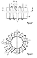
- Figure 42 illustrates the third embodiment of the invention adapted for use as a transformer.
- Figures 43 and 44 illustrate an embodiment of the invention adapted to a powder-based magnetic material, and thereby without magnetic field connectors.
- Figures 44 and 45 illustrate a section along lines VI-VI and V-V in figure 42.
- Figures 46 and 47 illustrate a core adapted to a powder-based magnetic material, and thereby without magnetic field connectors.
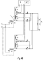
- Figure 48 shows an embodiment of the method according to the invention. This method comprises:
- T1 and T5 are excited by a DC signal.
- Figures 49 and 50 illustrate another method for rectification by means of a first and a second transformer device according to the invention, comprising (fig. 49, 50):
- Figure 50 is a time vs voltage diagram that shows how the method is implemented by controlling the voltage in the load by means of the voltages in the two control windings.
Landscapes
- Engineering & Computer Science (AREA)
- Power Engineering (AREA)
- Automation & Control Theory (AREA)
- Electromagnetism (AREA)
- General Physics & Mathematics (AREA)
- Radar, Positioning & Navigation (AREA)
- Physics & Mathematics (AREA)
- Dc-Dc Converters (AREA)
- Coils Of Transformers For General Uses (AREA)
- Ac-Ac Conversion (AREA)
- Electronic Switches (AREA)
- Coils Or Transformers For Communication (AREA)
- Rectifiers (AREA)
- Electrical Discharge Machining, Electrochemical Machining, And Combined Machining (AREA)
- Discharge-Lamp Control Circuits And Pulse- Feed Circuits (AREA)
Claims (5)
- Verfahren zum steuerbaren Umwandeln eines primären Wechselstroms/ einer primären Wechselspannung in einen sekundären Wechselstrom / eine sekundäre Wechselspannung durch Verwenden eines steuerbaren Transformatorgerätes, mit einem Körper (1) aus magnetischen Material, einer primären Windung (4), die um den Körper um eine erste Achse (A4) gewickelt ist, einer sekundären Windung (2), die um den Körper um eine zweite Achse (A2) im rechten Winkel zu der ersten Achse gewickelt ist, und einer Steuerwindung (3), die um den Körper um eine dritte Achse (A3) gewickelt ist, die mit der zweiten Achse zusammenfällt, mit:a) Speisen der primären Windung mit einem primären Wechselstrom/ einer primären Wechselspannung,b) Speisen der Steuerwindung mit einer Wechselspannung, die entweder in Phase oder 180° phasenverschoben in Bezug auf den primären Strom/ die primäre Spannung ist, undc) Speisen der Steuerwindung mit einem veränderlichen Strom, und dadurch Steuern des Umwandlungsverhältnisses des Transformators mittels des veränderlichen Steuerstroms.
- Verfahren nach Anspruch 1, weiter mit:- Erzwingen eine langsamen Änderung in der Amplitude der Steuerspannung, um so eine Veränderung in der Richtung der Domänen in dem magnetischen Material oder dem Magnetisierungswinkel zwischen der primären Windung und der sekundären Windung zu erreichen und um dadurch die Spannungsübertragung zu ändern,- Einführen einer Induktivität in den Steuerschaltkreis, um den Effekt der direkten transformierenden Verbindung zwischen der sekundären Windung und der Steuerwindung zu unterdrücken,- Erreichen einer zusätzlichen Steuerung durch Hinzufügen von elektromagnetischer Kraft von der sekundären Windung an die elektromagnetische Kraft der Steuerwindung und Beeinflussen des Magnetisierungswinkels zwischen der primären Windung und der sekundären Windung,- Kompensieren der Phasenwinkeldrehung, die zwischen der primären Windung und der sekundären Windung entsteht, die in Übereinstimmung mit der Lastbedingung variiert,- Erreichen eines gesteuerten Transformationseffektes durch Erhalten einer ersten primären Windungsantwort auf eine Laständerung in der sekundären Seite in Übereinstimmung mit dem Lenz'schen Gesetz.
- Verfahren nach Anspruch 1, wobei die Steuerwindung mit einer gepulsten Wechselspannung gespeist wird.
- Verfahren, das die Verwendung von zwei steuerbaren Transformatorgeräten umfasst, von denen jedes nach Anspruch 1 betrieben wird, wobei das Verfahren weiter umfasst:a1) Verbinden der primären Windung (T3) eines ersten Transformaors mit einer Leistungsversorgung,a2) Verbinden der primären Windung (T4) eines zweiten Transformators mit einer Leistungsversorgung,b1) Aktivieren der ersten Steuerwindung (T1) in dem ersten Transformator durch Zuführen einer Wechselspannung, während die zweite Steuerwindung (T5) in dem zweiten Transformator nicht aktiviert wird,
Gleichrichten der Spannung von der sekundären Windung (T2) des ersten Transformators und Anlegen der resultierenden Spannung (Vdc) an eine Last (U1),b2) Aktivieren der zweiten Steuerwindung (T5) in dem zweiten Transformator durch Zuführen einer Wechselspannung,
Gleichrichten der Spannung von der sekundären Windung (T6) des ersten Transformators und Anlegen der resultierenden Spannung (Vdc) an eine Last (U1), durch Steuern der Aktivierung der Steuerwindungen (T1 und T5), um die Länge der positiven und der negativen Gleichrichterperiode zu steuern, und Erhalten einer variablen Frequenzsteuerung von 0 bis 50 Hz. - Verfahren, das die Verwendung von zwei steuerbaren Transformatorgeräten umfasst, von denen jedes nach Anspruch 1 betrieben wird, wobei das Verfahren weiter umfasst:a1) Verbinden der primären Windung (T3) eines ersten Transformators mit einer Leistungsversorgung,a2) Verbinden der primären Windung (T4) eines zweiten Transformators mit der Leistungsversorgung,b1) Zuführen einer Wechselspannung an die Steuerwindung (T1) in dem ersten Transformatorb2) Zuführen einer Wechselspannung an die Steuerwindung (T5) in dem zweiten Transformator, wobei
die primäre Windung des ersten Transformators (T3) entgegengesetzt zu der primärem Windung des zweiten Transformators (T4) mit einer gemeinsamen Spannung verbunden ist,
die sekundären Windungen des ersten und des zweiten Transformators (T2, T6) parallel zu einer Last (Motor) verbunden sind, undc1) eine gepulste Steuerspannung (Vk1) in Phase und entgegengesetzt zu der Spannung in der primären Windung des ersten Transformators (T3) angelegt wird,c2) beim nächsten Nulldurchgang der Spannung an der primären Windung des ersten Transformators (T3) die Steuerspannung (Vk1) in der Steuerwindung des ersten Transformators (T1) entfernt wird, undc3) beim nächsten Nulldurchgang der Spannung eine gepulste Steuerspannung (Vk2) an die Steuerwindung des zweiten Transformators angelegt wird.
Applications Claiming Priority (5)
| Application Number | Priority Date | Filing Date | Title |
|---|---|---|---|
| NO20015689 | 2001-11-21 | ||
| NO20015689A NO319424B1 (no) | 2001-11-21 | 2001-11-21 | Fremgangsmate for styrbar omforming av en primaer vekselstrom/-spenning til en sekundaer vekselstrom/-spenning |
| US33313601P | 2001-11-27 | 2001-11-27 | |
| US333136P | 2001-11-27 | ||
| PCT/NO2002/000435 WO2003044613A1 (en) | 2001-11-21 | 2002-11-21 | Controllable transformer |
Publications (2)
| Publication Number | Publication Date |
|---|---|
| EP1449043A1 EP1449043A1 (de) | 2004-08-25 |
| EP1449043B1 true EP1449043B1 (de) | 2006-10-11 |
Family
ID=19913050
Family Applications (1)
| Application Number | Title | Priority Date | Filing Date |
|---|---|---|---|
| EP02803575A Expired - Lifetime EP1449043B1 (de) | 2001-11-21 | 2002-11-21 | Steuerbarer transformer |
Country Status (13)
| Country | Link |
|---|---|
| US (2) | US6788180B2 (de) |
| EP (1) | EP1449043B1 (de) |
| JP (1) | JP4398250B2 (de) |
| KR (1) | KR100981194B1 (de) |
| CN (1) | CN1615462A (de) |
| AT (1) | ATE342537T1 (de) |
| AU (1) | AU2002366186A1 (de) |
| CA (2) | CA2467989C (de) |
| DE (1) | DE60215381T2 (de) |
| ES (1) | ES2276983T3 (de) |
| NO (1) | NO319424B1 (de) |
| PT (1) | PT1449043E (de) |
| WO (1) | WO2003044613A1 (de) |
Families Citing this family (30)
| Publication number | Priority date | Publication date | Assignee | Title |
|---|---|---|---|---|
| CZ20033151A3 (cs) * | 2003-11-19 | 2005-07-13 | Jaroslav Foglar | Regulátor napětí, především pro regulaci výkonu |
| DE102004016944A1 (de) * | 2004-04-06 | 2005-10-27 | Patent-Treuhand-Gesellschaft für elektrische Glühlampen mbH | Wandlerschaltung mit gekoppelten Induktivitäten |
| US7271696B2 (en) * | 2004-12-14 | 2007-09-18 | Groupe Delta Xfo Inc. | Two part transformer core, transformer and method of manufacture |
| US20080106154A1 (en) * | 2006-11-07 | 2008-05-08 | Boyd Joseph J | Electromagnetic energy collector |
| NO328415B1 (no) * | 2008-03-17 | 2010-02-15 | Vetco Gray Scandinavia As | Innretning relatert til et offshore kabelsystem |
| BRPI0911459A2 (pt) | 2008-04-11 | 2018-03-20 | Magtech As | sistema de transmissão de energia |
| CN102185553B (zh) * | 2011-04-11 | 2012-11-21 | 山东大学 | 一种连续可控变压器 |
| US9389619B2 (en) | 2013-07-29 | 2016-07-12 | The Boeing Company | Transformer core flux control for power management |
| US9568563B2 (en) | 2012-07-19 | 2017-02-14 | The Boeing Company | Magnetic core flux sensor |
| US9455084B2 (en) | 2012-07-19 | 2016-09-27 | The Boeing Company | Variable core electromagnetic device |
| US9947450B1 (en) | 2012-07-19 | 2018-04-17 | The Boeing Company | Magnetic core signal modulation |
| US9159487B2 (en) * | 2012-07-19 | 2015-10-13 | The Boeing Company | Linear electromagnetic device |
| US9651633B2 (en) | 2013-02-21 | 2017-05-16 | The Boeing Company | Magnetic core flux sensor |
| US10186371B2 (en) * | 2013-07-08 | 2019-01-22 | Samsung Electronics Co., Ltd. | Magnetic field generation apparatus having planar structure |
| RU2552514C2 (ru) * | 2013-07-08 | 2015-06-10 | Корпорация "САМСУНГ ЭЛЕКТРОНИКС Ко., Лтд." | Планарное устройство для генерации магнитного поля с произвольным направлением |
| DE102013222435B4 (de) | 2013-11-05 | 2019-06-06 | SUMIDA Components & Modules GmbH | Magnetkernelement, Magnetkernmodul und ein das Magnetkernmodul verwendendes induktives Bauelement |
| CN103559981B (zh) | 2013-11-20 | 2018-05-22 | 戴珊珊 | 交流永磁增益变压装置及其调压控制方法 |
| DE102014116846A1 (de) | 2014-11-18 | 2016-05-19 | Manfred Diez | Elektromagnetische Netzspannungsregelung und Smart Grid Anwendung |
| CN115410804A (zh) | 2015-11-30 | 2022-11-29 | 鹰港科技有限公司 | 高压变压器 |
| FR3045925B1 (fr) * | 2015-12-22 | 2018-02-16 | Supergrid Institute | Transformateur electrique pour des equipements haute tension distants |
| US10403429B2 (en) | 2016-01-13 | 2019-09-03 | The Boeing Company | Multi-pulse electromagnetic device including a linear magnetic core configuration |
| BR112018068494A2 (pt) * | 2016-08-05 | 2019-01-22 | Faraday Grid Ltd | sistema e processo de abastecimento de potência elétrica |
| WO2018049473A1 (en) * | 2016-09-14 | 2018-03-22 | Faraday Grid Limited | An electrical power distribution network and process |
| EP3406434B1 (de) | 2017-05-22 | 2024-12-25 | Ratier-Figeac SAS | Verbundblatt und verfahren zur herstellung |
| DE102017209230B4 (de) * | 2017-05-31 | 2019-01-24 | Universität Stuttgart | Verfahren zum Betrieb eines Gleichspannungswandlers mit hoher Effizienz mittels dynamischer Regelung der Spuleninduktivität |
| EP3413322A1 (de) * | 2017-06-08 | 2018-12-12 | Goodrich Control Systems | Aktiver induktor |
| EP3925064B1 (de) * | 2019-05-21 | 2023-03-29 | Huawei Digital Power Technologies Co., Ltd. | Aufwärtswandler und steuerungsverfahren |
| CN112541154B (zh) * | 2020-11-26 | 2021-10-08 | 东南大学 | 一种磁路功率的计算方法 |
| DE102023000998A1 (de) | 2022-04-11 | 2023-10-12 | Sew-Eurodrive Gmbh & Co Kg | Transformator mit Ringkern |
| WO2024162179A1 (ja) * | 2023-01-31 | 2024-08-08 | 学校法人常翔学園 | 変圧器、変圧装置及び制御方法 |
Family Cites Families (28)
| Publication number | Priority date | Publication date | Assignee | Title |
|---|---|---|---|---|
| US1287982A (en) * | 1917-02-16 | 1918-12-17 | Western Electric Co | Modulating system. |
| US2284406A (en) * | 1940-03-01 | 1942-05-26 | Gen Electric | Transformer |
| US2883604A (en) * | 1957-02-08 | 1959-04-21 | Harry T Mortimer | Magnetic frequency changer |
| US3371217A (en) * | 1964-03-05 | 1968-02-27 | Sperry Rand Corp | Parametric information translating system |
| GB1209253A (en) | 1968-01-31 | 1970-10-21 | Ross & Catherall Ltd | Improvements in or relating to transformer cores |
| US3757201A (en) | 1972-05-19 | 1973-09-04 | L Cornwell | Electric power controlling or regulating system |
| US4004251A (en) * | 1975-11-03 | 1977-01-18 | General Electric Company | Inverter transformer |
| US4002999A (en) * | 1975-11-03 | 1977-01-11 | General Electric Company | Static inverter with controlled core saturation |
| FR2344109A1 (fr) | 1976-03-08 | 1977-10-07 | Ungari Serge | Transformateur statique a noyau central |
| DE2625354C3 (de) | 1976-06-04 | 1981-06-04 | Siemens AG, 1000 Berlin und 8000 München | Übertrager für Gleich- und Wechselstromsignale mit einem ferromagnetischen Kern, der mindestens zwei voneinander unabhängige Magnetflüsse zuläßt |
| US4210859A (en) | 1978-04-18 | 1980-07-01 | Technion Research & Development Foundation Ltd. | Inductive device having orthogonal windings |
| CA1118509A (fr) * | 1978-10-20 | 1982-02-16 | Gerald Roberge | Variable inductance |
| US4202031A (en) * | 1978-11-01 | 1980-05-06 | General Electric Company | Static inverter employing an assymetrically energized inductor |
| FR2452167A1 (fr) * | 1979-03-20 | 1980-10-17 | Aerospatiale | Procede pour la realisation d'une armature magnetique a structure divisee et armature ainsi obtenue |
| JPS5857718A (ja) * | 1981-09-30 | 1983-04-06 | Sony Corp | トランスのコア |
| US5187428A (en) * | 1991-02-26 | 1993-02-16 | Miller Electric Mfg. Co. | Shunt coil controlled transformer |
| US5404101A (en) * | 1992-02-27 | 1995-04-04 | Logue; Delmar L. | Rotary sensing device utilizing a rotating magnetic field within a hollow toroid core |
| SE9203331L (sv) | 1992-11-09 | 1994-05-10 | Asea Brown Boveri | Styrbar induktor samt användning av en sådan |
| SE515458C2 (sv) | 1996-03-15 | 2001-08-06 | Abb Research Ltd | Styrbar reaktor med återkopplad styrlindning |
| SE506893C2 (sv) * | 1996-05-23 | 1998-02-23 | Asea Brown Boveri | Styrbar induktor |
| SE511406C2 (sv) | 1997-01-08 | 1999-09-27 | Abb Ab | Styrbar induktor |
| US5936503A (en) * | 1997-02-14 | 1999-08-10 | Asea Brown Boveri Ab | Controllable inductor |
| JP2001519970A (ja) * | 1997-03-26 | 2001-10-23 | エービービー アクチボラゲット | 制御可能なインダクタのためのコア及びそれを製造するための方法 |
| US6307468B1 (en) * | 1999-07-20 | 2001-10-23 | Avid Identification Systems, Inc. | Impedance matching network and multidimensional electromagnetic field coil for a transponder interrogator |
| NO317045B1 (no) | 2000-05-24 | 2004-07-26 | Magtech As | Magnetisk pavirkbar strom- eller spenningsregulerende anordning |
| CN1284291C (zh) | 2000-09-26 | 2006-11-08 | 松下电器产业株式会社 | 线性传动装置的叠层磁芯及其制造方法 |
| EP1464062A1 (de) | 2002-11-01 | 2004-10-06 | Magtech As | Kupplungsvorrichtung |
| JP2006510088A (ja) | 2002-12-12 | 2006-03-23 | メグテック エーエス | 電源線の電圧安定化システム |
-
2001
- 2001-11-21 NO NO20015689A patent/NO319424B1/no not_active IP Right Cessation
-
2002
- 2002-11-21 EP EP02803575A patent/EP1449043B1/de not_active Expired - Lifetime
- 2002-11-21 ES ES02803575T patent/ES2276983T3/es not_active Expired - Lifetime
- 2002-11-21 JP JP2003546184A patent/JP4398250B2/ja not_active Expired - Fee Related
- 2002-11-21 AT AT02803575T patent/ATE342537T1/de active
- 2002-11-21 WO PCT/NO2002/000435 patent/WO2003044613A1/en not_active Ceased
- 2002-11-21 PT PT02803575T patent/PT1449043E/pt unknown
- 2002-11-21 AU AU2002366186A patent/AU2002366186A1/en not_active Abandoned
- 2002-11-21 KR KR1020047007824A patent/KR100981194B1/ko not_active Expired - Fee Related
- 2002-11-21 CN CNA028274156A patent/CN1615462A/zh active Pending
- 2002-11-21 US US10/300,752 patent/US6788180B2/en not_active Expired - Lifetime
- 2002-11-21 CA CA2467989A patent/CA2467989C/en not_active Expired - Lifetime
- 2002-11-21 CA CA2729421A patent/CA2729421C/en not_active Expired - Fee Related
- 2002-11-21 DE DE60215381T patent/DE60215381T2/de not_active Expired - Lifetime
-
2004
- 2004-07-16 US US10/892,657 patent/US7061356B2/en not_active Expired - Fee Related
Also Published As
| Publication number | Publication date |
|---|---|
| US20030117251A1 (en) | 2003-06-26 |
| KR100981194B1 (ko) | 2010-09-10 |
| AU2002366186A1 (en) | 2003-06-10 |
| PT1449043E (pt) | 2007-01-31 |
| NO319424B1 (no) | 2005-08-08 |
| CA2729421A1 (en) | 2003-05-30 |
| KR20050044585A (ko) | 2005-05-12 |
| US20050110605A1 (en) | 2005-05-26 |
| DE60215381T2 (de) | 2007-08-23 |
| CA2467989C (en) | 2012-04-24 |
| CA2467989A1 (en) | 2003-05-30 |
| NO20015689L (no) | 2003-05-22 |
| CA2729421C (en) | 2013-01-15 |
| WO2003044613A1 (en) | 2003-05-30 |
| JP4398250B2 (ja) | 2010-01-13 |
| US7061356B2 (en) | 2006-06-13 |
| JP2005522858A (ja) | 2005-07-28 |
| ES2276983T3 (es) | 2007-07-01 |
| US6788180B2 (en) | 2004-09-07 |
| CN1615462A (zh) | 2005-05-11 |
| NO20015689D0 (no) | 2001-11-21 |
| DE60215381D1 (de) | 2006-11-23 |
| EP1449043A1 (de) | 2004-08-25 |
| ATE342537T1 (de) | 2006-11-15 |
Similar Documents
| Publication | Publication Date | Title |
|---|---|---|
| CA2467989C (en) | Controllable transformer | |
| US7277302B2 (en) | 12-pulse converter including a filter choke incorporated in the rectifier | |
| US6101113A (en) | Transformers for multipulse AC/DC converters | |
| EP0716496A1 (de) | Dreiphasiger, bürstenloser, selbsterregender Synchrongenerator ohne Rotorerregerwicklung | |
| US6466466B1 (en) | Stable artificial neutral point in a three phase network of single phase rectifiers | |
| US4493016A (en) | Rectifier transformer | |
| TWI830063B (zh) | 三相磁性組件 | |
| RU2328051C2 (ru) | Трансформатор | |
| JP6504766B2 (ja) | 静止誘導電器 | |
| US4652771A (en) | Oscillating flux transformer | |
| US2265296A (en) | Magnetic modulator | |
| JP2000294438A (ja) | 分離型トランスの電力伝送方法及びその装置 | |
| US4378522A (en) | Adjustable current source | |
| JP3789333B2 (ja) | 電磁機器 | |
| JPS61161942A (ja) | 単相同期発電機の電圧補償回路 | |
| JP2007060831A (ja) | スイッチング電源装置 | |
| US11239763B2 (en) | Interphase power transformer for electrical systems | |
| JPH09330829A (ja) | 線形可変リアクトル | |
| RU2124776C1 (ru) | Многофункциональный трансформатор | |
| CN110197759A (zh) | 变压器、三相变压器及其接线方法 | |
| JPH10333758A (ja) | 電圧調整装置 | |
| JPH10214732A (ja) | 磁束制御形可変変圧器 | |
| JPH10285951A (ja) | インバータ出力回路用変圧器 | |
| JPH06176943A (ja) | 整流変圧器 |
Legal Events
| Date | Code | Title | Description |
|---|---|---|---|
| REG | Reference to a national code |
Ref country code: SE Ref legal event code: TRGR |
|
| PUAI | Public reference made under article 153(3) epc to a published international application that has entered the european phase |
Free format text: ORIGINAL CODE: 0009012 |
|
| 17P | Request for examination filed |
Effective date: 20040621 |
|
| AK | Designated contracting states |
Kind code of ref document: A1 Designated state(s): AT BE BG CH CY CZ DE DK EE ES FI FR GB GR IE IT LI LU MC NL PT SE SK TR |
|
| AX | Request for extension of the european patent |
Extension state: AL LT LV MK RO SI |
|
| 17Q | First examination report despatched |
Effective date: 20050520 |
|
| GRAP | Despatch of communication of intention to grant a patent |
Free format text: ORIGINAL CODE: EPIDOSNIGR1 |
|
| GRAS | Grant fee paid |
Free format text: ORIGINAL CODE: EPIDOSNIGR3 |
|
| GRAA | (expected) grant |
Free format text: ORIGINAL CODE: 0009210 |
|
| AK | Designated contracting states |
Kind code of ref document: B1 Designated state(s): AT BE BG CH CY CZ DE DK EE ES FI FR GB GR IE IT LI LU MC NL PT SE SK TR |
|
| AX | Request for extension of the european patent |
Extension state: LT LV SI |
|
| PG25 | Lapsed in a contracting state [announced via postgrant information from national office to epo] |
Ref country code: IT Free format text: LAPSE BECAUSE OF FAILURE TO SUBMIT A TRANSLATION OF THE DESCRIPTION OR TO PAY THE FEE WITHIN THE PRE;WARNING: LAPSES OF ITALIAN PATENTS WITH EFFECTIVE DATE BEFORE 2007 MAY HAVE OCCURRED AT ANY TIME BEFORE 2007. THE CORRECT EFFECTIVE DATE MAY BE DIFFERENT FROM THE ONE RECORDED.SCRIBED TIME-LIMIT Effective date: 20061011 Ref country code: NL Free format text: LAPSE BECAUSE OF FAILURE TO SUBMIT A TRANSLATION OF THE DESCRIPTION OR TO PAY THE FEE WITHIN THE PRESCRIBED TIME-LIMIT Effective date: 20061011 Ref country code: BE Free format text: LAPSE BECAUSE OF FAILURE TO SUBMIT A TRANSLATION OF THE DESCRIPTION OR TO PAY THE FEE WITHIN THE PRESCRIBED TIME-LIMIT Effective date: 20061011 Ref country code: CZ Free format text: LAPSE BECAUSE OF FAILURE TO SUBMIT A TRANSLATION OF THE DESCRIPTION OR TO PAY THE FEE WITHIN THE PRESCRIBED TIME-LIMIT Effective date: 20061011 Ref country code: SK Free format text: LAPSE BECAUSE OF FAILURE TO SUBMIT A TRANSLATION OF THE DESCRIPTION OR TO PAY THE FEE WITHIN THE PRESCRIBED TIME-LIMIT Effective date: 20061011 |
|
| REG | Reference to a national code |
Ref country code: GB Ref legal event code: FG4D |
|
| REG | Reference to a national code |
Ref country code: CH Ref legal event code: EP |
|
| REG | Reference to a national code |
Ref country code: IE Ref legal event code: FG4D |
|
| REF | Corresponds to: |
Ref document number: 60215381 Country of ref document: DE Date of ref document: 20061123 Kind code of ref document: P |
|
| PG25 | Lapsed in a contracting state [announced via postgrant information from national office to epo] |
Ref country code: MC Free format text: LAPSE BECAUSE OF NON-PAYMENT OF DUE FEES Effective date: 20061130 |
|
| PG25 | Lapsed in a contracting state [announced via postgrant information from national office to epo] |
Ref country code: DK Free format text: LAPSE BECAUSE OF FAILURE TO SUBMIT A TRANSLATION OF THE DESCRIPTION OR TO PAY THE FEE WITHIN THE PRESCRIBED TIME-LIMIT Effective date: 20070111 Ref country code: BG Free format text: LAPSE BECAUSE OF FAILURE TO SUBMIT A TRANSLATION OF THE DESCRIPTION OR TO PAY THE FEE WITHIN THE PRESCRIBED TIME-LIMIT Effective date: 20070111 |
|
| REG | Reference to a national code |
Ref country code: PT Ref legal event code: SC4A Free format text: AVAILABILITY OF NATIONAL TRANSLATION Effective date: 20070110 |
|
| REG | Reference to a national code |
Ref country code: CH Ref legal event code: NV Representative=s name: PATENTANWAELTE SCHAAD, BALASS, MENZL & PARTNER AG Ref country code: GR Ref legal event code: EP Ref document number: 20070400069 Country of ref document: GR |
|
| LTIE | Lt: invalidation of european patent or patent extension |
Effective date: 20061011 |
|
| NLV1 | Nl: lapsed or annulled due to failure to fulfill the requirements of art. 29p and 29m of the patents act | ||
| ET | Fr: translation filed | ||
| REG | Reference to a national code |
Ref country code: ES Ref legal event code: FG2A Ref document number: 2276983 Country of ref document: ES Kind code of ref document: T3 |
|
| PLBE | No opposition filed within time limit |
Free format text: ORIGINAL CODE: 0009261 |
|
| STAA | Information on the status of an ep patent application or granted ep patent |
Free format text: STATUS: NO OPPOSITION FILED WITHIN TIME LIMIT |
|
| 26N | No opposition filed |
Effective date: 20070712 |
|
| PG25 | Lapsed in a contracting state [announced via postgrant information from national office to epo] |
Ref country code: EE Free format text: LAPSE BECAUSE OF FAILURE TO SUBMIT A TRANSLATION OF THE DESCRIPTION OR TO PAY THE FEE WITHIN THE PRESCRIBED TIME-LIMIT Effective date: 20061011 |
|
| PG25 | Lapsed in a contracting state [announced via postgrant information from national office to epo] |
Ref country code: LU Free format text: LAPSE BECAUSE OF NON-PAYMENT OF DUE FEES Effective date: 20061121 |
|
| PG25 | Lapsed in a contracting state [announced via postgrant information from national office to epo] |
Ref country code: CY Free format text: LAPSE BECAUSE OF FAILURE TO SUBMIT A TRANSLATION OF THE DESCRIPTION OR TO PAY THE FEE WITHIN THE PRESCRIBED TIME-LIMIT Effective date: 20061011 |
|
| REG | Reference to a national code |
Ref country code: GB Ref legal event code: 732E Free format text: REGISTERED BETWEEN 20141002 AND 20141008 |
|
| REG | Reference to a national code |
Ref country code: FR Ref legal event code: CA Effective date: 20141106 |
|
| REG | Reference to a national code |
Ref country code: FR Ref legal event code: CL Name of requester: FJORDS PROCESSING AS, NO Effective date: 20141205 |
|
| REG | Reference to a national code |
Ref country code: FR Ref legal event code: PLFP Year of fee payment: 14 |
|
| PGFP | Annual fee paid to national office [announced via postgrant information from national office to epo] |
Ref country code: DE Payment date: 20151119 Year of fee payment: 14 Ref country code: GB Payment date: 20151118 Year of fee payment: 14 Ref country code: CH Payment date: 20151118 Year of fee payment: 14 Ref country code: IE Payment date: 20151119 Year of fee payment: 14 Ref country code: GR Payment date: 20151112 Year of fee payment: 14 Ref country code: TR Payment date: 20151113 Year of fee payment: 14 Ref country code: IT Payment date: 20151125 Year of fee payment: 14 Ref country code: FI Payment date: 20151111 Year of fee payment: 14 |
|
| PGFP | Annual fee paid to national office [announced via postgrant information from national office to epo] |
Ref country code: SE Payment date: 20151118 Year of fee payment: 14 Ref country code: FR Payment date: 20151119 Year of fee payment: 14 Ref country code: PT Payment date: 20151117 Year of fee payment: 14 Ref country code: ES Payment date: 20151111 Year of fee payment: 14 Ref country code: AT Payment date: 20151119 Year of fee payment: 14 |
|
| REG | Reference to a national code |
Ref country code: DE Ref legal event code: R119 Ref document number: 60215381 Country of ref document: DE |
|
| REG | Reference to a national code |
Ref country code: CH Ref legal event code: PL |
|
| REG | Reference to a national code |
Ref country code: SE Ref legal event code: EUG |
|
| REG | Reference to a national code |
Ref country code: AT Ref legal event code: MM01 Ref document number: 342537 Country of ref document: AT Kind code of ref document: T Effective date: 20161121 |
|
| GBPC | Gb: european patent ceased through non-payment of renewal fee |
Effective date: 20161121 |
|
| PG25 | Lapsed in a contracting state [announced via postgrant information from national office to epo] |
Ref country code: GR Free format text: LAPSE BECAUSE OF NON-PAYMENT OF DUE FEES Effective date: 20170612 Ref country code: LI Free format text: LAPSE BECAUSE OF NON-PAYMENT OF DUE FEES Effective date: 20161130 Ref country code: CH Free format text: LAPSE BECAUSE OF NON-PAYMENT OF DUE FEES Effective date: 20161130 Ref country code: FI Free format text: LAPSE BECAUSE OF NON-PAYMENT OF DUE FEES Effective date: 20161121 |
|
| REG | Reference to a national code |
Ref country code: IE Ref legal event code: MM4A |
|
| REG | Reference to a national code |
Ref country code: FR Ref legal event code: ST Effective date: 20170731 |
|
| PG25 | Lapsed in a contracting state [announced via postgrant information from national office to epo] |
Ref country code: AT Free format text: LAPSE BECAUSE OF NON-PAYMENT OF DUE FEES Effective date: 20161121 Ref country code: PT Free format text: LAPSE BECAUSE OF NON-PAYMENT OF DUE FEES Effective date: 20170522 Ref country code: SE Free format text: LAPSE BECAUSE OF NON-PAYMENT OF DUE FEES Effective date: 20161122 |
|
| PG25 | Lapsed in a contracting state [announced via postgrant information from national office to epo] |
Ref country code: FR Free format text: LAPSE BECAUSE OF NON-PAYMENT OF DUE FEES Effective date: 20161130 Ref country code: IT Free format text: LAPSE BECAUSE OF NON-PAYMENT OF DUE FEES Effective date: 20161121 |
|
| PG25 | Lapsed in a contracting state [announced via postgrant information from national office to epo] |
Ref country code: IE Free format text: LAPSE BECAUSE OF NON-PAYMENT OF DUE FEES Effective date: 20161121 Ref country code: DE Free format text: LAPSE BECAUSE OF NON-PAYMENT OF DUE FEES Effective date: 20170601 Ref country code: GB Free format text: LAPSE BECAUSE OF NON-PAYMENT OF DUE FEES Effective date: 20161121 |
|
| PG25 | Lapsed in a contracting state [announced via postgrant information from national office to epo] |
Ref country code: ES Free format text: LAPSE BECAUSE OF NON-PAYMENT OF DUE FEES Effective date: 20161122 |
|
| REG | Reference to a national code |
Ref country code: ES Ref legal event code: FD2A Effective date: 20181119 |
|
| PG25 | Lapsed in a contracting state [announced via postgrant information from national office to epo] |
Ref country code: TR Free format text: LAPSE BECAUSE OF NON-PAYMENT OF DUE FEES Effective date: 20161121 |