EP1448355B1 - Vorrichtung zum koextrudieren von kautschukmischungen - Google Patents
Vorrichtung zum koextrudieren von kautschukmischungen Download PDFInfo
- Publication number
- EP1448355B1 EP1448355B1 EP02750930A EP02750930A EP1448355B1 EP 1448355 B1 EP1448355 B1 EP 1448355B1 EP 02750930 A EP02750930 A EP 02750930A EP 02750930 A EP02750930 A EP 02750930A EP 1448355 B1 EP1448355 B1 EP 1448355B1
- Authority
- EP
- European Patent Office
- Prior art keywords
- extrusion
- rubber
- nozzle
- extruder
- wall
- Prior art date
- Legal status (The legal status is an assumption and is not a legal conclusion. Google has not performed a legal analysis and makes no representation as to the accuracy of the status listed.)
- Expired - Lifetime
Links
- 239000000203 mixture Substances 0.000 title claims abstract description 69
- 229920001971 elastomer Polymers 0.000 title claims abstract description 48
- 239000005060 rubber Substances 0.000 title claims abstract description 48
- 238000001125 extrusion Methods 0.000 claims abstract description 59
- 238000000034 method Methods 0.000 claims abstract description 15
- 238000011144 upstream manufacturing Methods 0.000 claims abstract description 6
- 238000004519 manufacturing process Methods 0.000 claims description 10
- 230000005611 electricity Effects 0.000 claims description 6
- 239000000615 nonconductor Substances 0.000 claims 1
- 230000002787 reinforcement Effects 0.000 description 14
- 150000001875 compounds Chemical class 0.000 description 9
- 239000000243 solution Substances 0.000 description 9
- VYPSYNLAJGMNEJ-UHFFFAOYSA-N Silicium dioxide Chemical compound O=[Si]=O VYPSYNLAJGMNEJ-UHFFFAOYSA-N 0.000 description 8
- 239000006229 carbon black Substances 0.000 description 6
- 239000012763 reinforcing filler Substances 0.000 description 5
- 241000283070 Equus zebra Species 0.000 description 4
- 239000002184 metal Substances 0.000 description 4
- 238000005096 rolling process Methods 0.000 description 4
- 239000000377 silicon dioxide Substances 0.000 description 4
- 230000003068 static effect Effects 0.000 description 4
- 230000006978 adaptation Effects 0.000 description 3
- 238000003490 calendering Methods 0.000 description 2
- 230000036961 partial effect Effects 0.000 description 2
- 244000043261 Hevea brasiliensis Species 0.000 description 1
- CBENFWSGALASAD-UHFFFAOYSA-N Ozone Chemical compound [O-][O+]=O CBENFWSGALASAD-UHFFFAOYSA-N 0.000 description 1
- 208000024780 Urticaria Diseases 0.000 description 1
- 238000009825 accumulation Methods 0.000 description 1
- 230000002411 adverse Effects 0.000 description 1
- 230000032683 aging Effects 0.000 description 1
- 239000007767 bonding agent Substances 0.000 description 1
- 238000004140 cleaning Methods 0.000 description 1
- 239000011231 conductive filler Substances 0.000 description 1
- 239000004020 conductor Substances 0.000 description 1
- 230000008094 contradictory effect Effects 0.000 description 1
- 230000007547 defect Effects 0.000 description 1
- 230000000694 effects Effects 0.000 description 1
- 230000007613 environmental effect Effects 0.000 description 1
- 235000012438 extruded product Nutrition 0.000 description 1
- 239000000945 filler Substances 0.000 description 1
- 239000000446 fuel Substances 0.000 description 1
- 239000003292 glue Substances 0.000 description 1
- 238000002347 injection Methods 0.000 description 1
- 239000007924 injection Substances 0.000 description 1
- 238000003780 insertion Methods 0.000 description 1
- 230000037431 insertion Effects 0.000 description 1
- 238000009434 installation Methods 0.000 description 1
- 230000000670 limiting effect Effects 0.000 description 1
- 230000007257 malfunction Effects 0.000 description 1
- VNWKTOKETHGBQD-UHFFFAOYSA-N methane Chemical compound C VNWKTOKETHGBQD-UHFFFAOYSA-N 0.000 description 1
- 229920003052 natural elastomer Polymers 0.000 description 1
- 229920001194 natural rubber Polymers 0.000 description 1
- 238000009877 rendering Methods 0.000 description 1
- 229920003051 synthetic elastomer Polymers 0.000 description 1
- 239000005061 synthetic rubber Substances 0.000 description 1
- 238000003466 welding Methods 0.000 description 1
Images

Classifications
-
- B—PERFORMING OPERATIONS; TRANSPORTING
- B29—WORKING OF PLASTICS; WORKING OF SUBSTANCES IN A PLASTIC STATE IN GENERAL
- B29C—SHAPING OR JOINING OF PLASTICS; SHAPING OF MATERIAL IN A PLASTIC STATE, NOT OTHERWISE PROVIDED FOR; AFTER-TREATMENT OF THE SHAPED PRODUCTS, e.g. REPAIRING
- B29C48/00—Extrusion moulding, i.e. expressing the moulding material through a die or nozzle which imparts the desired form; Apparatus therefor
- B29C48/16—Articles comprising two or more components, e.g. co-extruded layers
-
- B—PERFORMING OPERATIONS; TRANSPORTING
- B60—VEHICLES IN GENERAL
- B60C—VEHICLE TYRES; TYRE INFLATION; TYRE CHANGING; CONNECTING VALVES TO INFLATABLE ELASTIC BODIES IN GENERAL; DEVICES OR ARRANGEMENTS RELATED TO TYRES
- B60C19/00—Tyre parts or constructions not otherwise provided for
- B60C19/08—Electric-charge-dissipating arrangements
-
- B—PERFORMING OPERATIONS; TRANSPORTING
- B29—WORKING OF PLASTICS; WORKING OF SUBSTANCES IN A PLASTIC STATE IN GENERAL
- B29C—SHAPING OR JOINING OF PLASTICS; SHAPING OF MATERIAL IN A PLASTIC STATE, NOT OTHERWISE PROVIDED FOR; AFTER-TREATMENT OF THE SHAPED PRODUCTS, e.g. REPAIRING
- B29C48/00—Extrusion moulding, i.e. expressing the moulding material through a die or nozzle which imparts the desired form; Apparatus therefor
- B29C48/03—Extrusion moulding, i.e. expressing the moulding material through a die or nozzle which imparts the desired form; Apparatus therefor characterised by the shape of the extruded material at extrusion
- B29C48/07—Flat, e.g. panels
-
- B—PERFORMING OPERATIONS; TRANSPORTING
- B29—WORKING OF PLASTICS; WORKING OF SUBSTANCES IN A PLASTIC STATE IN GENERAL
- B29C—SHAPING OR JOINING OF PLASTICS; SHAPING OF MATERIAL IN A PLASTIC STATE, NOT OTHERWISE PROVIDED FOR; AFTER-TREATMENT OF THE SHAPED PRODUCTS, e.g. REPAIRING
- B29C48/00—Extrusion moulding, i.e. expressing the moulding material through a die or nozzle which imparts the desired form; Apparatus therefor
- B29C48/16—Articles comprising two or more components, e.g. co-extruded layers
- B29C48/18—Articles comprising two or more components, e.g. co-extruded layers the components being layers
- B29C48/19—Articles comprising two or more components, e.g. co-extruded layers the components being layers the layers being joined at their edges
-
- B—PERFORMING OPERATIONS; TRANSPORTING
- B29—WORKING OF PLASTICS; WORKING OF SUBSTANCES IN A PLASTIC STATE IN GENERAL
- B29C—SHAPING OR JOINING OF PLASTICS; SHAPING OF MATERIAL IN A PLASTIC STATE, NOT OTHERWISE PROVIDED FOR; AFTER-TREATMENT OF THE SHAPED PRODUCTS, e.g. REPAIRING
- B29C48/00—Extrusion moulding, i.e. expressing the moulding material through a die or nozzle which imparts the desired form; Apparatus therefor
- B29C48/16—Articles comprising two or more components, e.g. co-extruded layers
- B29C48/18—Articles comprising two or more components, e.g. co-extruded layers the components being layers
- B29C48/21—Articles comprising two or more components, e.g. co-extruded layers the components being layers the layers being joined at their surfaces
-
- B—PERFORMING OPERATIONS; TRANSPORTING
- B29—WORKING OF PLASTICS; WORKING OF SUBSTANCES IN A PLASTIC STATE IN GENERAL
- B29C—SHAPING OR JOINING OF PLASTICS; SHAPING OF MATERIAL IN A PLASTIC STATE, NOT OTHERWISE PROVIDED FOR; AFTER-TREATMENT OF THE SHAPED PRODUCTS, e.g. REPAIRING
- B29C48/00—Extrusion moulding, i.e. expressing the moulding material through a die or nozzle which imparts the desired form; Apparatus therefor
- B29C48/25—Component parts, details or accessories; Auxiliary operations
- B29C48/30—Extrusion nozzles or dies
- B29C48/305—Extrusion nozzles or dies having a wide opening, e.g. for forming sheets
- B29C48/307—Extrusion nozzles or dies having a wide opening, e.g. for forming sheets specially adapted for bringing together components, e.g. melts within the die
-
- B—PERFORMING OPERATIONS; TRANSPORTING
- B29—WORKING OF PLASTICS; WORKING OF SUBSTANCES IN A PLASTIC STATE IN GENERAL
- B29C—SHAPING OR JOINING OF PLASTICS; SHAPING OF MATERIAL IN A PLASTIC STATE, NOT OTHERWISE PROVIDED FOR; AFTER-TREATMENT OF THE SHAPED PRODUCTS, e.g. REPAIRING
- B29C48/00—Extrusion moulding, i.e. expressing the moulding material through a die or nozzle which imparts the desired form; Apparatus therefor
- B29C48/25—Component parts, details or accessories; Auxiliary operations
- B29C48/30—Extrusion nozzles or dies
- B29C48/35—Extrusion nozzles or dies with rollers
-
- B—PERFORMING OPERATIONS; TRANSPORTING
- B29—WORKING OF PLASTICS; WORKING OF SUBSTANCES IN A PLASTIC STATE IN GENERAL
- B29C—SHAPING OR JOINING OF PLASTICS; SHAPING OF MATERIAL IN A PLASTIC STATE, NOT OTHERWISE PROVIDED FOR; AFTER-TREATMENT OF THE SHAPED PRODUCTS, e.g. REPAIRING
- B29C48/00—Extrusion moulding, i.e. expressing the moulding material through a die or nozzle which imparts the desired form; Apparatus therefor
- B29C48/25—Component parts, details or accessories; Auxiliary operations
- B29C48/36—Means for plasticising or homogenising the moulding material or forcing it through the nozzle or die
- B29C48/395—Means for plasticising or homogenising the moulding material or forcing it through the nozzle or die using screws surrounded by a cooperating barrel, e.g. single screw extruders
- B29C48/397—Means for plasticising or homogenising the moulding material or forcing it through the nozzle or die using screws surrounded by a cooperating barrel, e.g. single screw extruders using a single screw
-
- B—PERFORMING OPERATIONS; TRANSPORTING
- B29—WORKING OF PLASTICS; WORKING OF SUBSTANCES IN A PLASTIC STATE IN GENERAL
- B29C—SHAPING OR JOINING OF PLASTICS; SHAPING OF MATERIAL IN A PLASTIC STATE, NOT OTHERWISE PROVIDED FOR; AFTER-TREATMENT OF THE SHAPED PRODUCTS, e.g. REPAIRING
- B29C48/00—Extrusion moulding, i.e. expressing the moulding material through a die or nozzle which imparts the desired form; Apparatus therefor
- B29C48/25—Component parts, details or accessories; Auxiliary operations
- B29C48/36—Means for plasticising or homogenising the moulding material or forcing it through the nozzle or die
- B29C48/49—Means for plasticising or homogenising the moulding material or forcing it through the nozzle or die using two or more extruders to feed one die or nozzle
-
- B—PERFORMING OPERATIONS; TRANSPORTING
- B60—VEHICLES IN GENERAL
- B60C—VEHICLE TYRES; TYRE INFLATION; TYRE CHANGING; CONNECTING VALVES TO INFLATABLE ELASTIC BODIES IN GENERAL; DEVICES OR ARRANGEMENTS RELATED TO TYRES
- B60C11/00—Tyre tread bands; Tread patterns; Anti-skid inserts
-
- B—PERFORMING OPERATIONS; TRANSPORTING
- B29—WORKING OF PLASTICS; WORKING OF SUBSTANCES IN A PLASTIC STATE IN GENERAL
- B29D—PRODUCING PARTICULAR ARTICLES FROM PLASTICS OR FROM SUBSTANCES IN A PLASTIC STATE
- B29D30/00—Producing pneumatic or solid tyres or parts thereof
- B29D30/06—Pneumatic tyres or parts thereof (e.g. produced by casting, moulding, compression moulding, injection moulding, centrifugal casting)
- B29D30/52—Unvulcanised treads, e.g. on used tyres; Retreading
- B29D2030/526—Unvulcanised treads, e.g. on used tyres; Retreading the tread comprising means for discharging the electrostatic charge, e.g. conductive elements or portions having conductivity higher than the tread rubber
-
- Y—GENERAL TAGGING OF NEW TECHNOLOGICAL DEVELOPMENTS; GENERAL TAGGING OF CROSS-SECTIONAL TECHNOLOGIES SPANNING OVER SEVERAL SECTIONS OF THE IPC; TECHNICAL SUBJECTS COVERED BY FORMER USPC CROSS-REFERENCE ART COLLECTIONS [XRACs] AND DIGESTS
- Y10—TECHNICAL SUBJECTS COVERED BY FORMER USPC
- Y10S—TECHNICAL SUBJECTS COVERED BY FORMER USPC CROSS-REFERENCE ART COLLECTIONS [XRACs] AND DIGESTS
- Y10S152/00—Resilient tires and wheels
- Y10S152/02—Static discharge
Definitions
- the present invention relates to a method for obtaining a tire having a plurality of mixtures comprising, as a majority filler, a non-conductive filler such as silica or mixtures lightly charged with carbon black, at least two of these mixtures constituting the tread.
- the invention also relates to apparatus for the implementation of such a method.
- one of the objectives of tire manufacturers is to produce a tire with both very low rolling resistance, excellent adhesion on both dry and wet or snow-covered or icy surfaces, very good wear resistance, and low rolling noise.
- the static electricity thus accumulated in a tire is likely to cause, when certain particular conditions are met, an unpleasant electric shock to the occupant of a vehicle, when it is brought to touch the body of the vehicle.
- This static electricity is, moreover, likely to hasten the aging of the tire due to the ozone generated by the electric discharge. It can also be the cause, depending on the nature of the ground and the vehicle, a malfunction of the radio on board the vehicle because of the interference it generates.
- Requirement EP 0 658 452 A1 describes the adaptation of principles known for a long time to a so-called modern tire, an adaptation that makes it possible to solve the main problems relating to the solutions proposed in various old documents and, in particular, the harmful heterogeneities introduced in tire architectures.
- the proposed solution consists in inserting a strip of conductive rubber compound or insert, extending preferably over the entire circumference of the tire and connecting the surface of the tread either to one of the crown plies or to the reinforcement frame. carcass, that is to say any other part of the sufficiently electrically conductive tire, the necessary electrical conductivity being conferred by the presence of a suitable carbon black.
- a first solution consists, as described in the French application FR 97/02276 ( FR-A-2759946 ) of the applicant, to ensure the electrical connection between two conductive or conductive first layers, separated by a third non-conductive layer, by at least one strip of rubber mix of small thickness, width and length, placed between the two faces of welding the third non-conductive layer and in contact with the conducting means making the first two layers connected by the connection.
- this method requires additional product installation and involves an additional manufacturing cost.
- a second solution consists, as described in the international application WO 99/43506 of the Applicant, to provide each non-conductive layer with a circumferential insert of conductive mixture and after extrusion of said layer by conventional extrusion means, and then to join the two products together before laying on the top, said layers having a common contact wall and the width of the insert of one of the layers at the contact wall being equal to at least 10 times that of the insert of the other layer at this same level.
- This method effectively makes each conductive layer and ensure the electrical connection between them and the carcass reinforcement.
- certain rubber compounds have rheological properties so different that they make it extremely difficult to bond them. This is particularly the case when one of the mixtures is more decohesive than the other.
- a bonding agent such as a glue or a specific bonding gum between the two
- coextrusion which has, moreover, a certain industrial economic interest. Indeed, in a coextrusion process, the different products that have been separately worked by extrusion screws are discharged to a common extrusion orifice for assembling said products under heat and pressure.
- the subject of the invention is a coextrusion apparatus and a method of implementing the apparatus, in particular intended for the manufacture of a tire comprising at least two layers of non-electrically conductive rubber mixes and a circumferential insert of conductive mixture allowing the dissipation of electrical charges induced by the rolling of the tire, the simplest possible and using the just necessary amount of product to achieve the insert.
- the invention also relates to the apparatus for coextrusion of rubber mixes which comprises a main extruder comprising an extrusion head comprising at least two flow channels each of a rubber mix, said channels opening on the same extrusion orifice at through which the two rubber mixtures are pushed back, the extrusion orifice being delimited by a first and a second wall, said apparatus also comprises at least one micro-extruder of a third rubber mix whose extrusion head is provided with its end of a nozzle, said nozzle passing through the two flow channels to insert the third rubber mix into each rubber mixture upstream of the extrusion orifice.
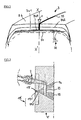
- the apparatus for producing a tread in the unvulcanized state comprising two coextruded layers of rubber mixes A and B and comprising a rubber mix insert C made by coextrusion with all the mixtures A and B.
- the extrusion head 10 comprises an upper vault 11 and a lower vault 13 delimiting with an intermediate support 12 two flow channels 14 and 15 each of one of the mixtures A and B.
- the flow channel 15 opens onto a first extrusion orifice 17 through which mixture B is discharged, delimited by a wall 121 of the support 12 and the surface 161 of a roller 16.
- This extrusion orifice 17 opens the door.
- a second extrusion orifice 18 in which is also discharged the mixture A arriving through the flow channel 14 so that the mixture B is disposed between the roller 16 and the mixture A.
- the extrusion orifice 18 is delimited by a first and a second wall respectively constituted by a wall 111 carried by the roof 11, belonging to an extrusion blade 19 and the outer surface 161 of the roller 16.
- the orifice Extrusion thus makes it possible to confer on the assembly constituted by the two coextruded mixtures the desired profile.
- the extruder is an extruder called "roll nose” in which the first wall 111 of the extrusion blade 19 is fixed and the second wall is movable and constituted by the outer surface 161 of a roller associated with the extruder.
- the invention is not limited to the use of this type of extruder, one can also consider an extruder 1 'said "flat nose” in which the first and second walls are constituted by the two fixed walls 191' and 192 'of an extrusion blade 19' as shown in the figure 3 .
- a very small extruder 2 commonly called a "micro-extruder”, fixedly mounted in the roof 11.
- This extruder 2 armed with a screw 21 and an extrusion head 22, has at its end a nozzle 23 fixed to the nose of the micro-extruder 2, and for extruding, in a desired profile and trace, an insert based on a third mixture in each mixture A and B uncured and hot passing through the flow channels 14 and 15.
- the extrusion head 22 forms a bend 221 so that the extrusion nozzle 23, fixed to the nose of the extrusion head through the two channels 14 and 15 and the support 12.
- a mixture of conductive rubber C intended to form the insert is thus extruded into each of the streams of mixtures A and B.
- the micro-extruder is mounted perpendicular to the axis of the roll 16, which prevents the extrusion head of said micro-extruder to form a bend.
- the extrusion nozzle 23 used with the micro-extruder 2 has a mobile die, in position of contact with the upper wall 131 of the vault 13 and passes through the support 12 thus allowing the passage of the mixture C over the entire length of the nozzle .
- the nozzle 23 is inclined relative to the direction perpendicular to the ends of the two flow channels 14 and 15 opening towards the extrusion orifice 18.
- This arrangement allows, in the example described, to insert the rubber mix C , and therefore to achieve the zebra in each flow channel, near the extrusion orifices 17 and 18 to prevent the zebra that is likely to undergo too much deformation between its zone of creation and the extrusion orifice concerned.
- this provision is to be determined according to a number of parameters, including the nature of the rubber mixes used, the temperature and pressure conditions within the extruders, the width and the nature of the rubbery mixture C. This is why according to these criteria, the nozzle may or may not form an angle of inclination with the direction of the flow channels and be more or less distant from the extrusion orifices.
- the arch 11 and the support 12 receive in a bore the nozzle 23 with a moving die which has on its cylindrical surface two slots 231, 232 made in a suitable section over part of its height so that each slot coincides with one of the channels. flow 14, 15.
- the contact between the base of the movable die nozzle 23 and the wall 131 of the arch 13 is maintained by the pressure of the conductive mixture acting on the section 230.
- the nozzle 23 can be fixed directly to the wall 131 of the vault 13.
- This device makes it possible to make welts whose width may vary over a range of about 0.1 mm to 2 mm without requiring a variation in width at the bases of the two layers of rubber compounds that will be in contact.
- this device if desired, to extrude the mixture C in a discontinuous manner depending on the desired applications for having, for example, a "dotted" zebra strip.
- the apparatus described above thus makes it possible, in accordance with the invention, in particular to manufacture a tread consisting of two non-conductive mixtures A and B and traversed by a conductive mixing insert C, of a tire as represented on the figure 2 .
- the tire 3, of size 315 / 80.R.22.5 designed to have a low rolling resistance, comprises a carcass reinforcement 31, composed of a metal sheet formed of inextensible metal cables embedded in a rubbery calendering mixture, conductive rendering of electrostatic charges through a carbon black commonly used as a reinforcing filler in mixtures.
- the carcass reinforcement 31 is surmounted at its top with a crown reinforcement 32, composed, in the example described, of plies and / or half-plies formed of metal ropes. All the cables of this crown reinforcement 32 are embedded in one or more rubber-like calendering mixture (s), conductive (s) electrostatic charges with a carbon black commonly used as a reinforcing filler in the mixtures.
- a crown reinforcement 32 composed, in the example described, of plies and / or half-plies formed of metal ropes. All the cables of this crown reinforcement 32 are embedded in one or more rubber-like calendering mixture (s), conductive (s) electrostatic charges with a carbon black commonly used as a reinforcing filler in the mixtures.
- the inner and outer layers 341 and 342 of the tread 34 are made conductive by means of a rubber or strip insert, which is in the form of a circumferential ring along the entire height of the two layers 341 and 342. for connecting the surface of the tread 34 coming into contact with the ground with the radially outermost ply of the crown reinforcement 32, formed of metal cables embedded in a rubber mixture loaded with a conventional and conductive carbon black .
- This insert 35 of very small axial width e on the tread surface is, in the case presented, unique and theoretically centered on the equatorial plane XX 'of the tire, and its trace on the contact surface 340 between the inner layer 341 and the radially outermost ply of the crown reinforcement 32 is rectilinear and circular.
- the insert 35 could be off-center, in particular in the case of the presence on the tread of a central groove; there could also be two inserts placed for example symmetrically with respect to the equatorial plane, or more, but in any case placed axially so that contact with the ground can be established regardless of the rate of wear of the tread. It can also be envisaged that the insert constitutes a circumferentially continuous or discontinuous ring.
- the rubber composition constituting the conductive connection 11 of the electrostatic charges is based on a natural rubber and / or synthetic rubbers, usually used in the manufacture of tires and particularly treads, and having as reinforcing filler a carbon black. conductor preferably usually used in the manufacture of tires.
- the method and the coextrusion apparatus according to the invention can be used for the introduction of insert in rubber compounds without a conduction appearance, such as for example for place one or more colored inserts in black rubber mixes.
Claims (9)
- Verfahren zur Herstellung eines Elements auf Basis von Kautschukgemischen, das für die Erzeugung eines Reifens bestimmt ist, umfassend die folgenden Schritte:- Extrusion mindestens zweier Schichten von Kautschukgemischen (A, B) durch Coextrusion auf einem Hauptextruder (1), der mit mindestens zwei Extrusionsschrauben versehen ist, die jeweils einen Abflusskanal (14, 15) umfassen, der in eine Extrusionsöffnung (18) mündet, die durch eine erste (111) und eine zweite Wand (161) begrenzt ist,
dadurch gekennzeichnet, dass- durch Coextrusion durch die beiden Schichten mindestens ein Einsatz (35) eines Kautschukgemisches (C) stromaufwärts zur Extrusionsöffnung mit Hilfe einer Düse (23) eines Mikro-Extruders (2) eingesetzt wird, wobei die Düse durch die beiden Abflusskanäle (14, 15) hindurchgeht. - Verfahren nach Anspruch 1, bei dem die Schichten von Kautschukgemischen Teile (341, 342) einer Lauffläche (34) darstellen.
- Verfahren nach Anspruch 2, bei dem die Kautschukgemische (A, B), die die Teile (341, 342) der Lauffläche bilden, elektrisch nicht leitend sind, und das vom Mikro-Extruder (2) extrudierte Kautschukgemisch (C) elektrisch leitend ist.
- Gerät zur Coextrusion von Kautschukgemischen, das einen Hauptextruder (1) besitzt, umfassend einen Extruderkopf (10), umfassend mindestens zwei Abflusskanäle (14, 15) für je ein Kautschukgemisch (A, B), wobei die Kanäle in eine Extrusionsöffnung (18) münden, durch die die beiden Kautschukgemische (A, B) geleitet werden, wobei die Extrusionsöffnung (18) von einer ersten (111) und einer zweiten Wand (161) begrenzt ist, wobei das Gerät auch mindestens einen Mikro-Extruder (2) für ein drittes Kautschukgemisch (C) besitzt, dessen Extruderkopf (22) an seinem Ende mit einer Düse (23) versehen ist, wobei die Düse durch die beiden Abflusskanäle (14, 15) geht, so dass das dritte Kautschukgemisch (C) in jedes Kautschukgemisch (A, B) stromaufwärts zur Extrusionsöffnung (18) eingesetzt wird.
- Gerät nach Anspruch 4, bei dem die erste und die zweite Wand des Extruderblättchens von den beiden festen Wänden eines Extruderblättchens (19) gebildet sind.
- Gerät nach Anspruch 4, bei dem, da die erste Wand (111), die die Extrusionsöffnung (18) begrenzt, fest ist, seine zweite Wand von der Außenfläche (161) von einer vom Hauptextruder (1) getragenen Walze (16) gebildet ist.
- Gerät nach einem der Ansprüche 4 oder 5, bei dem die Extrusionsdüse (23) eine bewegliche Matrize besitzt, auf einem Teil ihrer Höhe geschlitzt und in eine Bohrung eingesetzt ist.
- Gerät nach Anspruch 7, bei dem die Basis der Düse (23) mit einer Wand (131) eines der Abflusskanäle (15) durch den Druck des von diesem Mikro-Extruder (2) extrudierten Gemisches (C) in Kontakt gehalten wird.
- Gerät nach Anspruch 7, bei dem die Basis der Düse (23) an einer Wand (131) eines der Abflusskanäle (15) befestigt ist.
Applications Claiming Priority (3)
| Application Number | Priority Date | Filing Date | Title |
|---|---|---|---|
| FR0106489 | 2001-05-16 | ||
| FR0106489 | 2001-05-16 | ||
| PCT/EP2002/005333 WO2002092322A1 (fr) | 2001-05-16 | 2002-05-15 | Appareillage de coextrusion de melanges caoutchouteux |
Publications (2)
| Publication Number | Publication Date |
|---|---|
| EP1448355A1 EP1448355A1 (de) | 2004-08-25 |
| EP1448355B1 true EP1448355B1 (de) | 2008-11-19 |
Family
ID=8863374
Family Applications (1)
| Application Number | Title | Priority Date | Filing Date |
|---|---|---|---|
| EP02750930A Expired - Lifetime EP1448355B1 (de) | 2001-05-16 | 2002-05-15 | Vorrichtung zum koextrudieren von kautschukmischungen |
Country Status (12)
| Country | Link |
|---|---|
| US (1) | US6994817B2 (de) |
| EP (1) | EP1448355B1 (de) |
| JP (1) | JP4374192B2 (de) |
| KR (1) | KR20030020371A (de) |
| CN (1) | CN1238176C (de) |
| AT (1) | ATE414601T1 (de) |
| BR (1) | BR0205350B1 (de) |
| CA (1) | CA2420772A1 (de) |
| DE (1) | DE60229974D1 (de) |
| PL (1) | PL363908A1 (de) |
| RU (1) | RU2286255C2 (de) |
| WO (1) | WO2002092322A1 (de) |
Families Citing this family (25)
| Publication number | Priority date | Publication date | Assignee | Title |
|---|---|---|---|---|
| US20020157747A1 (en) * | 2001-03-12 | 2002-10-31 | Bridgestone Corporation | Tire, device for extruding unvulcanized tread rubber for the tire, and method of extruding unvulcanized tread rubber for the tire |
| KR100513240B1 (ko) * | 2003-11-04 | 2005-09-07 | 금호타이어 주식회사 | 트레드에 방전로를 갖는 타이어 압출성형장치의 다이세트 |
| US20080142130A1 (en) * | 2005-03-16 | 2008-06-19 | Yukihiro Kiwaki | Pneumatic Tire |
| CA2691052A1 (en) * | 2007-06-27 | 2008-12-31 | Sekisui Chemical Co., Ltd. | Apparatus and method for manufacturing multiplex interlayer for safety glass |
| US8062017B2 (en) * | 2008-10-13 | 2011-11-22 | The Goodyear Tire & Rubber Co | Splice bar for tire tread extrusion apparatus |
| US8016580B2 (en) * | 2009-01-28 | 2011-09-13 | The Goodyear Tire & Rubber Company | Assembly and a method for extruding a tire component |
| WO2011027562A1 (ja) * | 2009-09-07 | 2011-03-10 | 株式会社クラレ | Led用反射板およびそれを備える発光装置 |
| US9375980B2 (en) * | 2010-07-16 | 2016-06-28 | Exxonmobil Chemical Patents Inc. | Adhesive extrusion for dynamically vulcanized thermoplastic elastomer laminates |
| NL2006420C2 (en) * | 2011-03-18 | 2012-09-19 | Apollo Vredestein Bv | Method of manufacturing an antistatic vehicle tire and vehicle tire obtainable by the method. |
| NL2006728C2 (en) * | 2011-05-06 | 2012-11-08 | Apollo Vredestein Bv | Method and device for manufacturing an antistatic vehicle tire. |
| NL2006729C2 (en) * | 2011-05-06 | 2012-11-08 | Apollo Vredestein Bv | Method and device for manufacturing an antistatic vehicle tire. |
| US9085104B2 (en) | 2011-07-20 | 2015-07-21 | Nordson Corporation | Sculpted extrusion die |
| DE102012104691A1 (de) * | 2012-05-31 | 2013-12-05 | Continental Reifen Deutschland Gmbh | Verfahren zur Herstellung einer Mischungsbahn und Verfahren zur Herstellung einer Materialbahn aus zwei Mischungsbahnen |
| FR3006620B1 (fr) * | 2013-06-10 | 2015-12-11 | Batscap Sa | Filiere pour la fabrication d'un film par extrusion |
| DE102015202171A1 (de) * | 2015-02-06 | 2016-08-11 | Continental Reifen Deutschland Gmbh | Verfahren und Vorrichtung zur Herstellung eines mehrschichtig zusammengesetzten Rohlaufstreifens |
| FR3046104B1 (fr) * | 2015-12-23 | 2017-12-22 | Michelin & Cie | Procede de coextrusion d’un profile caoutchouteux complexe destine a la fabrication d’un pneumatique |
| FR3046105B1 (fr) | 2015-12-23 | 2017-12-22 | Michelin & Cie | Tete de coextrusion d’un profile caoutchouteux complexe destine a la fabrication d’un pneumatique |
| FR3060436A1 (fr) | 2016-12-20 | 2018-06-22 | Compagnie Generale Des Etablissements Michelin | Procede de coextrusion d’un profile caoutchouteux complexe destine a la fabrication d’un pneumatique |
| FR3060435A1 (fr) | 2016-12-20 | 2018-06-22 | Compagnie Generale Des Etablissements Michelin | Tete de coextrusion d'un profile caoutchouteux complexe destine a la fabrication d'un pneumatique |
| WO2019002782A1 (fr) | 2017-06-30 | 2019-01-03 | Compagnie Generale Des Etablissements Michelin | Tete d'extrusion avec chenaux pour la réalisation d'inserts dans une bande profilée destinée à la fabrication d'un pneumatique et procédé d'extrusion correspondant |
| FR3071760B1 (fr) * | 2017-10-04 | 2021-01-22 | Michelin & Cie | Tete d'extrusion d'un profile complexe comprenant un insert dans un melange fortement elastique |
| FR3072896A1 (fr) | 2017-10-27 | 2019-05-03 | Compagnie Generale Des Etablissements Michelin | Tete d’extrusion d’un profile complexe forme de profiles juxtaposes |
| CN108215118A (zh) * | 2018-01-25 | 2018-06-29 | 正新橡胶(中国)有限公司 | 一种生产导电轮胎的挤出口型 |
| CN115803173A (zh) * | 2020-07-22 | 2023-03-14 | 株式会社神户制钢所 | 金属构件、以及使用具备其的装置的橡胶材料的加工方法 |
| FR3117398B1 (fr) * | 2020-12-16 | 2023-10-06 | Continental Reifen Deutschland Gmbh | Installation d’extrusion améliorée pour la fabrication de bande de profilé |
Family Cites Families (18)
| Publication number | Priority date | Publication date | Assignee | Title |
|---|---|---|---|---|
| US2342576A (en) | 1941-08-01 | 1944-02-22 | Wingfoot Corp | Tire construction |
| DE3325017C2 (de) | 1983-07-11 | 1985-11-28 | Continental Gummi-Werke Ag, 3000 Hannover | Preßkopf zum Herstellen von flachen zusammenhängenden Profilsträngen aus plastischen Kautschuk- oder Kunststoffmischungen verschiedener Zusammensetzung |
| US4539169A (en) | 1983-07-29 | 1985-09-03 | The Goodyear Tire & Rubber Company | Apparatus and method for forming a co-extrusion from extruded strips |
| US5017118A (en) * | 1989-06-16 | 1991-05-21 | The Goodyear Tire & Rubber Company | Apparatus for forming a coextrusion from extruded strips |
| FR2673187B1 (fr) | 1991-02-25 | 1994-07-01 | Michelin & Cie | Composition de caoutchouc et enveloppes de pneumatiques a base de ladite composition. |
| FR2700291A1 (fr) | 1993-01-08 | 1994-07-13 | Michelin & Cie | Appareil d'extrusion et procédé d'extrusion pour mélanges de caoutchouc cru. |
| IT1264990B1 (it) | 1993-12-14 | 1996-10-17 | Pirelli | Pneumatico antistatico con mescole a basso tenore di nero di carbonio |
| CA2140999A1 (en) | 1994-11-07 | 1996-05-08 | Jennifer Leigh Gabor | Triplex tread |
| EP0753391B1 (de) * | 1995-07-13 | 2001-09-19 | Sumitomo Rubber Industries Ltd. | Extrusionsvorrichtung für Elastomer |
| FR2759946B1 (fr) | 1997-02-24 | 1999-04-09 | Michelin & Cie | Pneumatique a plusieurs melanges non conducteurs |
| IT1290520B1 (it) * | 1997-04-03 | 1998-12-04 | Pirelli | Metodo ed apparato di estrusione per realizzare fasce battistrada per pneumatici di veicoli |
| DE69833734T2 (de) | 1997-08-07 | 2007-01-04 | Bridgestone Corp. | Luftreifen und Verfahren zu seiner Herstellung |
| US6294119B1 (en) | 1997-12-26 | 2001-09-25 | Bridgestone Corporation | Production of unvulcanized tread rubber for pneumatic tires |
| DE69940193D1 (de) * | 1998-02-26 | 2009-02-12 | Michelin & Cie | Elektrisch leitender reifen und vorrichtungen zum extrudieren von leitenden profilen |
| JP3863298B2 (ja) | 1998-08-05 | 2006-12-27 | 株式会社ブリヂストン | 未加硫ゴム押出方法 |
| ES2238242T3 (es) * | 1999-11-23 | 2005-09-01 | Societe De Technologie Michelin | Aparato para la coextrusion de mezclas de caucho. |
| US20020157747A1 (en) * | 2001-03-12 | 2002-10-31 | Bridgestone Corporation | Tire, device for extruding unvulcanized tread rubber for the tire, and method of extruding unvulcanized tread rubber for the tire |
| US6746227B2 (en) * | 2001-06-19 | 2004-06-08 | The Goodyear Tire & Rubber Company | Tire tread die |
-
2002
- 2002-05-15 CN CNB028016939A patent/CN1238176C/zh not_active Expired - Fee Related
- 2002-05-15 CA CA002420772A patent/CA2420772A1/fr not_active Abandoned
- 2002-05-15 AT AT02750930T patent/ATE414601T1/de not_active IP Right Cessation
- 2002-05-15 WO PCT/EP2002/005333 patent/WO2002092322A1/fr active Application Filing
- 2002-05-15 BR BRPI0205350-0A patent/BR0205350B1/pt not_active IP Right Cessation
- 2002-05-15 JP JP2002589239A patent/JP4374192B2/ja not_active Expired - Fee Related
- 2002-05-15 DE DE60229974T patent/DE60229974D1/de not_active Expired - Lifetime
- 2002-05-15 EP EP02750930A patent/EP1448355B1/de not_active Expired - Lifetime
- 2002-05-15 KR KR10-2003-7000602A patent/KR20030020371A/ko not_active Application Discontinuation
- 2002-05-15 PL PL02363908A patent/PL363908A1/xx unknown
- 2002-05-15 RU RU2003105224/12A patent/RU2286255C2/ru not_active IP Right Cessation
-
2003
- 2003-02-13 US US10/366,529 patent/US6994817B2/en not_active Expired - Lifetime
Also Published As
| Publication number | Publication date |
|---|---|
| KR20030020371A (ko) | 2003-03-08 |
| EP1448355A1 (de) | 2004-08-25 |
| ATE414601T1 (de) | 2008-12-15 |
| WO2002092322A1 (fr) | 2002-11-21 |
| US20030136498A1 (en) | 2003-07-24 |
| BR0205350A (pt) | 2003-04-22 |
| DE60229974D1 (de) | 2009-01-02 |
| CN1238176C (zh) | 2006-01-25 |
| RU2286255C2 (ru) | 2006-10-27 |
| PL363908A1 (en) | 2004-11-29 |
| JP2004525012A (ja) | 2004-08-19 |
| BR0205350B1 (pt) | 2010-10-19 |
| CN1463220A (zh) | 2003-12-24 |
| CA2420772A1 (fr) | 2002-11-21 |
| US6994817B2 (en) | 2006-02-07 |
| JP4374192B2 (ja) | 2009-12-02 |
Similar Documents
| Publication | Publication Date | Title |
|---|---|---|
| EP1448355B1 (de) | Vorrichtung zum koextrudieren von kautschukmischungen | |
| EP1103391B1 (de) | Vorrichtung zum Coextrudieren von Kautschukmischungen | |
| EP1058623B1 (de) | Elektrisch leitender reifen und vorrichtung zum extrudieren eines profiles mit leitfähigem einsatz | |
| EP1659005B1 (de) | Elektrisch leitender Gummistreifen | |
| EP1060089B1 (de) | Elektrisch leitender reifen und vorrichtungen zum extrudieren von leitenden profilen | |
| EP2214897B1 (de) | Verfahren zur herstellung eines reifens mit einem elektrisch leitenden einsatz durch wickeln von streifen | |
| EP2268478A1 (de) | Drahtschicht mit elektrisch leitenden bereichen | |
| EP3393748A1 (de) | Verfahren zum coextrudieren eines komplexen kautschukprofils zur herstellung eines reifens | |
| EP0721856B1 (de) | Dichtungsprofil und Verfahren zu dessen Herstellung | |
| EP0963302B1 (de) | Reifen mit mehreren nichtleitenden mischungen | |
| FR2991266A1 (fr) | Profile de lame d'essuyage et son procede de fabrication | |
| FR2957020A1 (fr) | Pneumatique pour vehicules comportant une bande de roulement constituee de plusieurs melanges et une armature de carcasse radiale formee d'au moins deux couches. | |
| EP3645236B1 (de) | Extrusionskopf mit kanälen zur herstellung von einsätzen in einem profilband zur herstellung eines luftreifens und entsprechendes extrusionsverfahren | |
| EP1117545B1 (de) | Verstärkungsgürtel für radialen reifen | |
| EP2542428A1 (de) | Fahrzeugreifen mit profil aus mehreren verbindungen und karkassenverstärkung aus mindestens zwei schichten | |
| WO2017025828A1 (fr) | Pneumatique comprenant un fil conducteur | |
| FR2871285A1 (fr) | Cable comportant plusieurs conducteurs isoles enveloppes dans une meme gaine et procede de fabrication d'un tel cable | |
| FR3075694A3 (fr) | Pneumatique comprenant un cordon conducteur | |
| FR2586379A3 (fr) | Pneumatique radial |
Legal Events
| Date | Code | Title | Description |
|---|---|---|---|
| PUAI | Public reference made under article 153(3) epc to a published international application that has entered the european phase |
Free format text: ORIGINAL CODE: 0009012 |
|
| 17P | Request for examination filed |
Effective date: 20031216 |
|
| AK | Designated contracting states |
Kind code of ref document: A1 Designated state(s): AT BE CH CY DE DK ES FI FR GB GR IE IT LI LU MC NL PT SE TR |
|
| AX | Request for extension of the european patent |
Extension state: AL LT LV MK RO SI |
|
| GRAP | Despatch of communication of intention to grant a patent |
Free format text: ORIGINAL CODE: EPIDOSNIGR1 |
|
| GRAS | Grant fee paid |
Free format text: ORIGINAL CODE: EPIDOSNIGR3 |
|
| GRAA | (expected) grant |
Free format text: ORIGINAL CODE: 0009210 |
|
| AK | Designated contracting states |
Kind code of ref document: B1 Designated state(s): AT BE CH CY DE DK ES FI FR GB GR IE IT LI LU MC NL PT SE TR |
|
| REG | Reference to a national code |
Ref country code: GB Ref legal event code: FG4D Free format text: NOT ENGLISH |
|
| REG | Reference to a national code |
Ref country code: CH Ref legal event code: EP |
|
| REG | Reference to a national code |
Ref country code: IE Ref legal event code: FG4D Free format text: LANGUAGE OF EP DOCUMENT: FRENCH |
|
| REF | Corresponds to: |
Ref document number: 60229974 Country of ref document: DE Date of ref document: 20090102 Kind code of ref document: P |
|
| PG25 | Lapsed in a contracting state [announced via postgrant information from national office to epo] |
Ref country code: ES Free format text: LAPSE BECAUSE OF FAILURE TO SUBMIT A TRANSLATION OF THE DESCRIPTION OR TO PAY THE FEE WITHIN THE PRESCRIBED TIME-LIMIT Effective date: 20090301 Ref country code: AT Free format text: LAPSE BECAUSE OF FAILURE TO SUBMIT A TRANSLATION OF THE DESCRIPTION OR TO PAY THE FEE WITHIN THE PRESCRIBED TIME-LIMIT Effective date: 20081119 |
|
| NLV1 | Nl: lapsed or annulled due to failure to fulfill the requirements of art. 29p and 29m of the patents act | ||
| PG25 | Lapsed in a contracting state [announced via postgrant information from national office to epo] |
Ref country code: FI Free format text: LAPSE BECAUSE OF FAILURE TO SUBMIT A TRANSLATION OF THE DESCRIPTION OR TO PAY THE FEE WITHIN THE PRESCRIBED TIME-LIMIT Effective date: 20081119 Ref country code: NL Free format text: LAPSE BECAUSE OF FAILURE TO SUBMIT A TRANSLATION OF THE DESCRIPTION OR TO PAY THE FEE WITHIN THE PRESCRIBED TIME-LIMIT Effective date: 20081119 |
|
| REG | Reference to a national code |
Ref country code: IE Ref legal event code: FD4D |
|
| PG25 | Lapsed in a contracting state [announced via postgrant information from national office to epo] |
Ref country code: IE Free format text: LAPSE BECAUSE OF FAILURE TO SUBMIT A TRANSLATION OF THE DESCRIPTION OR TO PAY THE FEE WITHIN THE PRESCRIBED TIME-LIMIT Effective date: 20081119 Ref country code: DK Free format text: LAPSE BECAUSE OF FAILURE TO SUBMIT A TRANSLATION OF THE DESCRIPTION OR TO PAY THE FEE WITHIN THE PRESCRIBED TIME-LIMIT Effective date: 20081119 |
|
| PG25 | Lapsed in a contracting state [announced via postgrant information from national office to epo] |
Ref country code: SE Free format text: LAPSE BECAUSE OF FAILURE TO SUBMIT A TRANSLATION OF THE DESCRIPTION OR TO PAY THE FEE WITHIN THE PRESCRIBED TIME-LIMIT Effective date: 20090219 Ref country code: PT Free format text: LAPSE BECAUSE OF FAILURE TO SUBMIT A TRANSLATION OF THE DESCRIPTION OR TO PAY THE FEE WITHIN THE PRESCRIBED TIME-LIMIT Effective date: 20090420 |
|
| PLBE | No opposition filed within time limit |
Free format text: ORIGINAL CODE: 0009261 |
|
| STAA | Information on the status of an ep patent application or granted ep patent |
Free format text: STATUS: NO OPPOSITION FILED WITHIN TIME LIMIT |
|
| 26N | No opposition filed |
Effective date: 20090820 |
|
| BERE | Be: lapsed |
Owner name: SOC. DE TECHNOLOGIE MICHELIN Effective date: 20090531 Owner name: MICHELIN RECHERCHE ET TECHNIQUE S.A. Effective date: 20090531 |
|
| PG25 | Lapsed in a contracting state [announced via postgrant information from national office to epo] |
Ref country code: MC Free format text: LAPSE BECAUSE OF NON-PAYMENT OF DUE FEES Effective date: 20090531 |
|
| REG | Reference to a national code |
Ref country code: CH Ref legal event code: PL |
|
| GBPC | Gb: european patent ceased through non-payment of renewal fee |
Effective date: 20090515 |
|
| PG25 | Lapsed in a contracting state [announced via postgrant information from national office to epo] |
Ref country code: CH Free format text: LAPSE BECAUSE OF NON-PAYMENT OF DUE FEES Effective date: 20090531 Ref country code: LI Free format text: LAPSE BECAUSE OF NON-PAYMENT OF DUE FEES Effective date: 20090531 |
|
| PG25 | Lapsed in a contracting state [announced via postgrant information from national office to epo] |
Ref country code: GB Free format text: LAPSE BECAUSE OF NON-PAYMENT OF DUE FEES Effective date: 20090515 |
|
| PG25 | Lapsed in a contracting state [announced via postgrant information from national office to epo] |
Ref country code: BE Free format text: LAPSE BECAUSE OF NON-PAYMENT OF DUE FEES Effective date: 20090531 |
|
| PG25 | Lapsed in a contracting state [announced via postgrant information from national office to epo] |
Ref country code: GR Free format text: LAPSE BECAUSE OF FAILURE TO SUBMIT A TRANSLATION OF THE DESCRIPTION OR TO PAY THE FEE WITHIN THE PRESCRIBED TIME-LIMIT Effective date: 20090220 |
|
| PG25 | Lapsed in a contracting state [announced via postgrant information from national office to epo] |
Ref country code: LU Free format text: LAPSE BECAUSE OF NON-PAYMENT OF DUE FEES Effective date: 20090515 |
|
| PG25 | Lapsed in a contracting state [announced via postgrant information from national office to epo] |
Ref country code: TR Free format text: LAPSE BECAUSE OF FAILURE TO SUBMIT A TRANSLATION OF THE DESCRIPTION OR TO PAY THE FEE WITHIN THE PRESCRIBED TIME-LIMIT Effective date: 20081119 |
|
| PG25 | Lapsed in a contracting state [announced via postgrant information from national office to epo] |
Ref country code: CY Free format text: LAPSE BECAUSE OF FAILURE TO SUBMIT A TRANSLATION OF THE DESCRIPTION OR TO PAY THE FEE WITHIN THE PRESCRIBED TIME-LIMIT Effective date: 20081119 |
|
| REG | Reference to a national code |
Ref country code: FR Ref legal event code: PLFP Year of fee payment: 15 |
|
| REG | Reference to a national code |
Ref country code: FR Ref legal event code: PLFP Year of fee payment: 16 |
|
| REG | Reference to a national code |
Ref country code: FR Ref legal event code: PLFP Year of fee payment: 17 |
|
| PGFP | Annual fee paid to national office [announced via postgrant information from national office to epo] |
Ref country code: DE Payment date: 20180522 Year of fee payment: 17 |
|
| PGFP | Annual fee paid to national office [announced via postgrant information from national office to epo] |
Ref country code: IT Payment date: 20180530 Year of fee payment: 17 Ref country code: FR Payment date: 20180522 Year of fee payment: 17 |
|
| REG | Reference to a national code |
Ref country code: DE Ref legal event code: R079 Ref document number: 60229974 Country of ref document: DE Free format text: PREVIOUS MAIN CLASS: B29C0047560000 Ipc: B29C0048490000 |
|
| REG | Reference to a national code |
Ref country code: DE Ref legal event code: R119 Ref document number: 60229974 Country of ref document: DE |
|
| PG25 | Lapsed in a contracting state [announced via postgrant information from national office to epo] |
Ref country code: IT Free format text: LAPSE BECAUSE OF NON-PAYMENT OF DUE FEES Effective date: 20190515 Ref country code: DE Free format text: LAPSE BECAUSE OF NON-PAYMENT OF DUE FEES Effective date: 20191203 |
|
| PG25 | Lapsed in a contracting state [announced via postgrant information from national office to epo] |
Ref country code: FR Free format text: LAPSE BECAUSE OF NON-PAYMENT OF DUE FEES Effective date: 20190531 |