EP1448024A2 - Equipement du chauffage avec deux domaines - Google Patents
Equipement du chauffage avec deux domaines Download PDFInfo
- Publication number
- EP1448024A2 EP1448024A2 EP04000818A EP04000818A EP1448024A2 EP 1448024 A2 EP1448024 A2 EP 1448024A2 EP 04000818 A EP04000818 A EP 04000818A EP 04000818 A EP04000818 A EP 04000818A EP 1448024 A2 EP1448024 A2 EP 1448024A2
- Authority
- EP
- European Patent Office
- Prior art keywords
- region
- power
- heating device
- area
- maximum
- Prior art date
- Legal status (The legal status is an assumption and is not a legal conclusion. Google has not performed a legal analysis and makes no representation as to the accuracy of the status listed.)
- Granted
Links
- 238000010438 heat treatment Methods 0.000 title claims abstract description 56
- 239000002241 glass-ceramic Substances 0.000 claims abstract description 11
- 239000004020 conductor Substances 0.000 claims description 6
- 238000010411 cooking Methods 0.000 claims description 6
- 238000012544 monitoring process Methods 0.000 claims description 4
- 239000000463 material Substances 0.000 claims description 2
- 238000013021 overheating Methods 0.000 description 3
- 230000001681 protective effect Effects 0.000 description 3
- 230000009286 beneficial effect Effects 0.000 description 2
- 238000013459 approach Methods 0.000 description 1
- 230000003247 decreasing effect Effects 0.000 description 1
- 230000001419 dependent effect Effects 0.000 description 1
- 238000013461 design Methods 0.000 description 1
- 238000000034 method Methods 0.000 description 1
- 230000001105 regulatory effect Effects 0.000 description 1
- 238000010792 warming Methods 0.000 description 1
Images

Classifications
-
- H—ELECTRICITY
- H05—ELECTRIC TECHNIQUES NOT OTHERWISE PROVIDED FOR
- H05B—ELECTRIC HEATING; ELECTRIC LIGHT SOURCES NOT OTHERWISE PROVIDED FOR; CIRCUIT ARRANGEMENTS FOR ELECTRIC LIGHT SOURCES, IN GENERAL
- H05B3/00—Ohmic-resistance heating
- H05B3/68—Heating arrangements specially adapted for cooking plates or analogous hot-plates
- H05B3/74—Non-metallic plates, e.g. vitroceramic, ceramic or glassceramic hobs, also including power or control circuits
- H05B3/748—Resistive heating elements, i.e. heating elements exposed to the air, e.g. coil wire heater
-
- H—ELECTRICITY
- H05—ELECTRIC TECHNIQUES NOT OTHERWISE PROVIDED FOR
- H05B—ELECTRIC HEATING; ELECTRIC LIGHT SOURCES NOT OTHERWISE PROVIDED FOR; CIRCUIT ARRANGEMENTS FOR ELECTRIC LIGHT SOURCES, IN GENERAL
- H05B3/00—Ohmic-resistance heating
- H05B3/68—Heating arrangements specially adapted for cooking plates or analogous hot-plates
- H05B3/74—Non-metallic plates, e.g. vitroceramic, ceramic or glassceramic hobs, also including power or control circuits
- H05B3/746—Protection, e.g. overheat cutoff, hot plate indicator
-
- H—ELECTRICITY
- H05—ELECTRIC TECHNIQUES NOT OTHERWISE PROVIDED FOR
- H05B—ELECTRIC HEATING; ELECTRIC LIGHT SOURCES NOT OTHERWISE PROVIDED FOR; CIRCUIT ARRANGEMENTS FOR ELECTRIC LIGHT SOURCES, IN GENERAL
- H05B2213/00—Aspects relating both to resistive heating and to induction heating, covered by H05B3/00 and H05B6/00
- H05B2213/07—Heating plates with temperature control means
Definitions
- the invention relates to a heating device according to the preamble of claim 1.
- a heating device is in particular for a cooking area with a glass ceramic hob suitable
- the heating time or warm-up time for radiant heaters as heating devices on the one hand depends on a adjusted glass-ceramic surface temperature and the quality of the cookware used and on the other hand, from the rated power of the radiant heater and thus its power density. In many cases, it is desirable to shorten this cooking time to a comfortable operation and to achieve fast cooking.
- the power density of a radiant heater However, it can not be increased to infinity. at Radiant heaters with BandMapleitern can from a certain power density the heating conductor temperature is no longer in the specified Upper limits are kept.
- Values for power densities in such radiant heaters are called, which represent a good compromise between the cooking time, quality of the cookware used and the heating conductor temperature.
- An advantageous power density can be close to 8 watts / cm 2 .
- radiant heaters with a nominal diameter of 140mm and 180mm such a power density is used successfully.
- the invention is based on the object, an aforementioned heating device to deal with the problems of the state of the Technique can be avoided and especially the size of a Radiant heater regardless of the power density or a Switching capacity of protection temperature limiters made more variable can be.
- a heating device is in at least a first and split a second area.
- a first area can be from monitored for a first over-temperature fuse. This can for example, be a rod regulator or a protection temperature limiter, the at least partially overlaps this first area or above runs.
- the first area has a maximum first power. This is matched to the above values.
- a second area of the heater is operated without monitoring by the first overtemperature fuse.
- the second area is operated at all without over-temperature protection. This is achieved by the maximum area coverage of the second area being approximately 2.5 watts / cm 2 .
- the heating device divided into two parts, so to speak.
- a first area is operated with a critical power density and must therefore have a protective temperature limiter.
- This first area can be chosen so large that the protective temperature limiter the resulting power just manage or switch.
- the area of the To increase radiant heaters a second area is added. This second area will in any case be without supervision operated by the over-temperature fuse of the first area, preferably without any monitoring by an overtemperature fuse.
- a value is chosen as the power density, which for a glass ceramic is technically possible and permissible.
- a separate over-temperature fuse could be used for the second Be provided area. This would increase the effort, but also improve safety.
- the second region can rest against the first region, advantageously at least along the half outer border. This gives you an approximate elongated heating device.
- the second area surrounds the first area, where they can be arranged concentrically. While the lateral connection of a second area to a first area in about a known elongated roasting heater corresponds, is a concentric arrangement for use either smaller or large round cookware advantageous.
- the performance for the first range more than that for a radiant heater of this size usual basic service amount.
- the performance the maximum value of the overtemperature fuse for example one Stabreglers, approach.
- one performance for the first Range of a maximum of 2500 or 2700 watts be provided at one round area with a diameter of 230mm.
- the first area a switchable power have, which can be switched to the basic power. It is provided that the maximum first power is then present if the switchable power is also applied.
- a switchable Power can be, for example, a boil or the like his.
- the performance for the second area may, in particular due to the lower power density, much lower. For example 600 watts can be provided here. Because this performance is beneficial in the outer or edge region is present as a second area, in which also Cooking pots with not very even floor get up, this is Performance in any case decreased. Thus, too much warming a glass ceramic hob avoided here. Furthermore has in heating mode without pot, so if no heat output removed is, the glass ceramic in the edge area due to the larger area the biggest heat loss. Even so, she is overheating protected.
- the heating device have a controller or be connected to it.
- This controller can be an additional contact to the circuit of a basic service of Heating device or a switchable power for the first Range to the total combined maximum first power.
- the additional power can be defined, for example, as a boost and be used.
- the heating device can have an electronic control, for example, with a touch switch arrangement for input.
- Another relay can be provided to the switchable Power in addition to the base load to the total maximum first To switch power.
- a radiant heater is used as the heating device, which have a heating conductor made of resistance material can.
- the heating conductor is preferably in a so-called flat band shape, where he is standing upright on an insulating pad and partially embedded in it.
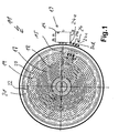
- a radiant heater 11 is shown in plan view, as he known per se. Its heated area is controlled by a rod regulator 13 overlapped.
- the temperature limiter or rod controller 13 is with his Housing 14 attached to the side of the radiant heater 11.
- Of the Sensor rod 15 protrudes in the radial direction over the center of the radiant heater 11 a bit out.
- the heating area of the radiant heater 11 is subdivided into a first one innermost region 17.
- the first region 17 is of an annular surrounded in the middle second area 19. This in turn is from Surrounding a relatively narrow circumferential third region 21, which forms the outermost heating area.
- the first region 17 is formed by first heating coils 18, the are laid meandering.
- This basic structure of a radiant heater For example, from EP 590 315, incorporated herein by reference expressly referred to.
- the second heating area 19 is formed by second heating coils 20.
- the third region 21 is again formed by third heating convolutions 22, which, as can be seen from Fig. 1, from a single loop consist.
- the Schuwindened 18, 20 and 22 are for example advantageous a heating tape formed in upright ribbon shape. You can be specially selected with regard to their characteristics certain power distribution or area performance achieved during operation or to achieve overall performance. It can also be seen that the Heating coils 18 of the first region 17 with a smaller distance from each other run as the second heating coils 20 of the second area 19th
- a connection of the heating coils to a power supply such as power electronics or a so-called clocking energy regulator.
- the heating coils 18 and 20 of the first and second areas are respectively over the top terminal lug 24a contacted, as can be seen.
- This connection banner 24a is connected to the housing 14 of the rod controller 13. Your electrical connection is thus monitored by the rod controller 13 and interrupted in case of overheating to the switch off the first heating area 17 and the second heating area 19.
- the rod controller 13 in this way and a distinction between the first area 17 and the second region 19 in overtemperature case not possible. It would be insofar as possible in a further embodiment of the embodiment, Such a distinction is possible by means of a further bar controller do. However, this plays for the invention in the frame discussed here not matter.
- the third heating coil 22 of the outer third region 21 is over the Connection lugs 24c and 24d connected. These are without that Interposing the rod controller 13 connected to a power supply. They are therefore not monitored by the rod controller 13 concerning overtemperature.
- FIG. 2 is a schematic thermal image of the radiant heater.
- FIG 11 of FIG. 1 in operation. Due to the different surface markings the temperature that prevails is displayed. ever brighter, the higher the temperature. The gradation is per brightness level 10 ° C.
- the first area 17 is predominantly the brightest, with the temperature here is between 545 ° C and 564 ° C respectively at about 555 ° C.
- the second region 19 has temperatures in the range of 524 ° C to 544 ° C.
- the third region 21 has predominantly temperatures in the Range between 494 ° C and 514 ° C or about 500 ° C.
- the radiant heater 11 is a two-circuit radiant heater. It has a diameter of 230 mm and a total nominal power of 2800 W. It accounts for the first area 17 1100 W, the second area 19 also 1100 W and the third area 21 600 W. This 600 W are the so-called unprotected or unregulated power. From Fig. 2 it can be seen that here the temperature in about 50 ° to 60 ° lower than in the first or second region, which are centrally in the radiant heater 11. Further, the area power of the third region 21 is less than 2.5 W / cm 2 , while the power density in the first and second regions is 7.8 W / cm 2 .
- Fig. 2 is thus proven that with heating areas with the previously described properties, ie in particular the outermost Heating area with low area performance, a radiant heater with additional power can be provided, which does not have a Rod controller or not regulated by a single common rod controller must become.
- the radiant heater In the operation of the radiant heater, it is such that in single-circuit operation only the first area 17 is active. In the two-circuit operation of the second area 19 and the third area 21, although electrically separate, but timed together.
- the third heating area 21 could be the same be switched off, but not directly by the rod controller 13, but by its property as a signal generator indirectly. This Although not always because of the thermal load on the surface of the third area 21 is necessary. This would be a uniform Operation of all heating areas possible, so not from the glow pattern of the radiant heater, the outermost area continues to glow brightly, while the central area is dark.
Landscapes
- Chemical & Material Sciences (AREA)
- Engineering & Computer Science (AREA)
- Ceramic Engineering (AREA)
- Electric Stoves And Ranges (AREA)
- Control Of Resistance Heating (AREA)
- Superconductors And Manufacturing Methods Therefor (AREA)
- Control Of Combustion (AREA)
- Resistance Heating (AREA)
Priority Applications (1)
| Application Number | Priority Date | Filing Date | Title |
|---|---|---|---|
| SI200430604T SI1448024T1 (sl) | 2003-02-17 | 2004-01-16 | Grelna priprava z dvema podrocjema |
Applications Claiming Priority (2)
| Application Number | Priority Date | Filing Date | Title |
|---|---|---|---|
| DE10307246A DE10307246A1 (de) | 2003-02-17 | 2003-02-17 | Heizungseinrichtung mit zwei Bereichen |
| DE10307246 | 2003-02-17 |
Publications (3)
| Publication Number | Publication Date |
|---|---|
| EP1448024A2 true EP1448024A2 (fr) | 2004-08-18 |
| EP1448024A3 EP1448024A3 (fr) | 2005-10-19 |
| EP1448024B1 EP1448024B1 (fr) | 2007-11-14 |
Family
ID=32668113
Family Applications (1)
| Application Number | Title | Priority Date | Filing Date |
|---|---|---|---|
| EP04000818A Expired - Lifetime EP1448024B1 (fr) | 2003-02-17 | 2004-01-16 | Equipement du chauffage avec deux domaines |
Country Status (6)
| Country | Link |
|---|---|
| US (1) | US7053340B2 (fr) |
| EP (1) | EP1448024B1 (fr) |
| AT (1) | ATE378797T1 (fr) |
| DE (2) | DE10307246A1 (fr) |
| ES (1) | ES2297282T3 (fr) |
| SI (1) | SI1448024T1 (fr) |
Cited By (2)
| Publication number | Priority date | Publication date | Assignee | Title |
|---|---|---|---|---|
| DE202013007643U1 (de) | 2013-08-21 | 2013-09-05 | E.G.O. Elektro-Gerätebau GmbH | Heizeinrichtung für eine Kochstelle in einem Kochfeld und Kochfeld |
| DE102013216290A1 (de) | 2013-08-16 | 2015-02-19 | E.G.O. Elektro-Gerätebau GmbH | Heizeinrichtung und Verfahren zum Betrieb einer Heizeinrichtung |
Families Citing this family (12)
| Publication number | Priority date | Publication date | Assignee | Title |
|---|---|---|---|---|
| CA2583743A1 (fr) * | 2004-10-15 | 2006-04-27 | Duke Manufacturing Company | Bar pour servir des aliments |
| DE102004059779A1 (de) * | 2004-12-07 | 2006-06-08 | E.G.O. Elektro-Gerätebau GmbH | Vorrichtung und Verfahren zur Ansteuerung eines Mehrkreis-Heizkörpers |
| JP4728021B2 (ja) * | 2005-03-17 | 2011-07-20 | 日本碍子株式会社 | 均熱性評価方法及び均熱性評価装置 |
| WO2008127330A1 (fr) | 2007-04-12 | 2008-10-23 | Duke Manufacturing Co. | Bar de service pour aliments |
| FR2952289B1 (fr) * | 2009-11-06 | 2012-02-24 | Pillivuyt | Ustensile de cuisson en ceramique |
| ES2564849B1 (es) * | 2014-09-24 | 2017-01-12 | BSH Electrodomésticos España S.A. | Dispositivo de campo de cocción |
| DE102016224069A1 (de) * | 2016-12-02 | 2018-06-07 | E.G.O. Elektro-Gerätebau GmbH | Kochgerät mit einer Kochplatte und einer Heizeinrichtung darunter |
| US10132504B1 (en) * | 2017-05-15 | 2018-11-20 | Backer Ehp Inc. | Dual coil electric heating element |
| US11067288B2 (en) | 2017-05-15 | 2021-07-20 | Backer Ehp Inc. | Dual coil electric heating element |
| KR102177948B1 (ko) | 2018-10-16 | 2020-11-12 | 엘지전자 주식회사 | 전기 히터 |
| USD955168S1 (en) | 2019-07-03 | 2022-06-21 | Backer Ehp Inc. | Electric heating element |
| US11581156B2 (en) | 2019-07-03 | 2023-02-14 | Backer Ehp Inc. | Dual coil electric heating element |
Citations (6)
| Publication number | Priority date | Publication date | Assignee | Title |
|---|---|---|---|---|
| US4327280A (en) * | 1979-02-07 | 1982-04-27 | Micropore International Limited | Smooth top cookers |
| US4430558A (en) * | 1980-07-22 | 1984-02-07 | Micropore International Ltd. | Electric radiant heater unit for a glass ceramic top cooker |
| EP0551172A2 (fr) * | 1992-01-10 | 1993-07-14 | Ceramaspeed Limited | Plaque de cuisson en vitro-céramique muni de plusieurs zones de chauffage |
| US5498853A (en) * | 1992-09-03 | 1996-03-12 | E.G.O. Elektro-Gerate Blanc U. Fischer | Heater, particularly for kitchen appliances |
| GB2324946A (en) * | 1997-05-01 | 1998-11-04 | Ceramaspeed Ltd | Radiant electric heater with visible radiation shielding |
| DE19814949A1 (de) * | 1997-05-07 | 1998-11-12 | Aeg Hausgeraete Gmbh | Gareinrichtung mit Induktionsbeheizung und Widerstandsbeheizung |
Family Cites Families (8)
| Publication number | Priority date | Publication date | Assignee | Title |
|---|---|---|---|---|
| NZ196104A (en) * | 1980-02-01 | 1984-08-24 | Micropore International Ltd | Cooker plate with twin element:thermal cut-out for one |
| DE3206024A1 (de) * | 1982-02-19 | 1983-09-08 | Bosch-Siemens Hausgeräte GmbH, 7000 Stuttgart | Elektrokochplatte, vorzugsweise glaskeramik-kochmulde |
| DE3314501A1 (de) * | 1983-04-21 | 1984-10-25 | Ego Elektro Blanc & Fischer | Heizelement, insbesondere strahlungs-heizelement fuer die beheizung von glaskeramikplatten |
| AT386714B (de) * | 1983-07-07 | 1988-10-10 | Electrovac | Vorrichtung zur heissanzeige und zur regelung bzw. begrenzung der temperatur von strahlungsbzw. kontaktheizkoerpern von elektrischen kochgeraeten |
| DE3333645A1 (de) * | 1983-09-17 | 1985-04-11 | E.G.O. Elektro-Geräte Blanc u. Fischer, 7519 Oberderdingen | Temperaturbegrenzer fuer eine glaskeramikkocheinheit |
| DE4022846C2 (de) * | 1990-07-18 | 1994-08-11 | Schott Glaswerke | Vorrichtung zur Leistungssteuerung und -begrenzung bei einer Heizfläche aus Glaskeramik oder einem vergleichbaren Material |
| GB9102133D0 (en) * | 1991-01-31 | 1991-03-13 | Ceramaspeed Ltd | Radiant electric heaters |
| GB2333406B (en) * | 1998-01-16 | 2001-10-10 | Ceramaspeed Ltd | Radiant electric heater |
-
2003
- 2003-02-17 DE DE10307246A patent/DE10307246A1/de not_active Withdrawn
-
2004
- 2004-01-16 EP EP04000818A patent/EP1448024B1/fr not_active Expired - Lifetime
- 2004-01-16 AT AT04000818T patent/ATE378797T1/de active
- 2004-01-16 SI SI200430604T patent/SI1448024T1/sl unknown
- 2004-01-16 ES ES04000818T patent/ES2297282T3/es not_active Expired - Lifetime
- 2004-01-16 DE DE502004005460T patent/DE502004005460D1/de not_active Expired - Lifetime
- 2004-01-29 US US10/767,655 patent/US7053340B2/en not_active Expired - Lifetime
Patent Citations (6)
| Publication number | Priority date | Publication date | Assignee | Title |
|---|---|---|---|---|
| US4327280A (en) * | 1979-02-07 | 1982-04-27 | Micropore International Limited | Smooth top cookers |
| US4430558A (en) * | 1980-07-22 | 1984-02-07 | Micropore International Ltd. | Electric radiant heater unit for a glass ceramic top cooker |
| EP0551172A2 (fr) * | 1992-01-10 | 1993-07-14 | Ceramaspeed Limited | Plaque de cuisson en vitro-céramique muni de plusieurs zones de chauffage |
| US5498853A (en) * | 1992-09-03 | 1996-03-12 | E.G.O. Elektro-Gerate Blanc U. Fischer | Heater, particularly for kitchen appliances |
| GB2324946A (en) * | 1997-05-01 | 1998-11-04 | Ceramaspeed Ltd | Radiant electric heater with visible radiation shielding |
| DE19814949A1 (de) * | 1997-05-07 | 1998-11-12 | Aeg Hausgeraete Gmbh | Gareinrichtung mit Induktionsbeheizung und Widerstandsbeheizung |
Cited By (5)
| Publication number | Priority date | Publication date | Assignee | Title |
|---|---|---|---|---|
| DE102013216290A1 (de) | 2013-08-16 | 2015-02-19 | E.G.O. Elektro-Gerätebau GmbH | Heizeinrichtung und Verfahren zum Betrieb einer Heizeinrichtung |
| EP2844029A1 (fr) | 2013-08-16 | 2015-03-04 | E.G.O. Elektro-Gerätebau GmbH | Dispositif de chauffage et son procédé de fonctionnement |
| DE102013216290B4 (de) * | 2013-08-16 | 2015-09-03 | E.G.O. Elektro-Gerätebau GmbH | Heizeinrichtung und Verfahren zum Betrieb einer Heizeinrichtung |
| US9894716B2 (en) | 2013-08-16 | 2018-02-13 | E.G.O. Elektro-Geraetebau Gmbh | Heating device and method for operating a heating device |
| DE202013007643U1 (de) | 2013-08-21 | 2013-09-05 | E.G.O. Elektro-Gerätebau GmbH | Heizeinrichtung für eine Kochstelle in einem Kochfeld und Kochfeld |
Also Published As
| Publication number | Publication date |
|---|---|
| EP1448024A3 (fr) | 2005-10-19 |
| SI1448024T1 (sl) | 2008-04-30 |
| EP1448024B1 (fr) | 2007-11-14 |
| US7053340B2 (en) | 2006-05-30 |
| ATE378797T1 (de) | 2007-11-15 |
| DE502004005460D1 (de) | 2007-12-27 |
| DE10307246A1 (de) | 2004-08-26 |
| ES2297282T3 (es) | 2008-05-01 |
| US20040182850A1 (en) | 2004-09-23 |
Similar Documents
| Publication | Publication Date | Title |
|---|---|---|
| DE4130337C2 (de) | Verfahren zum Betrieb einer elektrischen Heizeinheit und elektrische Heizeinheit | |
| EP0103741B1 (fr) | Elément chauffant, en particulier élément chauffant radiant pour le chauffage de plaques en céramique | |
| DE69816222T2 (de) | Flexibler Flächenheizkörper mit Kontrolleinheit | |
| EP1448024B1 (fr) | Equipement du chauffage avec deux domaines | |
| DE4022846C2 (de) | Vorrichtung zur Leistungssteuerung und -begrenzung bei einer Heizfläche aus Glaskeramik oder einem vergleichbaren Material | |
| DE69320667T2 (de) | Glaskeramik-Kochmulde mit mehreren Heizzonen | |
| EP0250880B1 (fr) | Corps de chauffage à rayonnement | |
| DE69317453T2 (de) | Vorrichtung zur Steuerung oder Begrenzung der Temperatur in einem elektrischen Kochgerät | |
| DE102013216290B4 (de) | Heizeinrichtung und Verfahren zum Betrieb einer Heizeinrichtung | |
| EP1258171A1 (fr) | Espace de cuisson a sonde pyrometrique | |
| DE69931980T2 (de) | Elektrischer Strahlungsheizkörper | |
| CH654459A5 (de) | Elektrischer strahlungsheizkoerper. | |
| EP3764738B1 (fr) | Appareil de préparation d'aliments pourvu de conducteurs électriques ptc à commutation parallèle | |
| EP1774831B1 (fr) | Dispositif pour commuter plusieurs systemes de chauffage d'un appareil de cuisson et appareil de cuisson equipe d'un tel dispositif | |
| DE3314501A1 (de) | Heizelement, insbesondere strahlungs-heizelement fuer die beheizung von glaskeramikplatten | |
| DE69915884T2 (de) | Verbesserungen an elektrisch geheizten kochgefässen | |
| WO2001062046A1 (fr) | Ensemble plaque de cuisson dote d'un capteur de temperature | |
| EP1774554B1 (fr) | Dispositif pour commander plusieurs unites de chauffage d'un appareil de cuisson, et appareil de cuisson equipe d'un tel dispositif | |
| DE69614647T2 (de) | Elektrischer Strahlungsheizkörper und Verfahren zu dessen Betrieb | |
| WO2001062047A1 (fr) | Espace de cuisson a sonde pyrometrique | |
| DE3518124A1 (de) | Elektrokochgeraet | |
| DE102006022571A1 (de) | Vorrichtung zur Steuerung von Strahlungsheizkörpern | |
| EP2983449B1 (fr) | Procede d'acceleration d'un processus de cuisson, dispositif de commande et appareil de cuisson correspondant | |
| DE3601634C2 (de) | Vorrichtung zum Regeln oder Begrenzen der Temperatur von Strahlungs- oder Kontaktheizkörpern | |
| DE2758465C2 (fr) |
Legal Events
| Date | Code | Title | Description |
|---|---|---|---|
| PUAI | Public reference made under article 153(3) epc to a published international application that has entered the european phase |
Free format text: ORIGINAL CODE: 0009012 |
|
| AK | Designated contracting states |
Kind code of ref document: A2 Designated state(s): AT BE BG CH CY CZ DE DK EE ES FI FR GB GR HU IE IT LI LU MC NL PT RO SE SI SK TR |
|
| AX | Request for extension of the european patent |
Extension state: AL LT LV MK |
|
| PUAL | Search report despatched |
Free format text: ORIGINAL CODE: 0009013 |
|
| AK | Designated contracting states |
Kind code of ref document: A3 Designated state(s): AT BE BG CH CY CZ DE DK EE ES FI FR GB GR HU IE IT LI LU MC NL PT RO SE SI SK TR |
|
| AX | Request for extension of the european patent |
Extension state: AL LT LV MK |
|
| 17P | Request for examination filed |
Effective date: 20051118 |
|
| AKX | Designation fees paid |
Designated state(s): AT BE BG CH CY CZ DE DK EE ES FI FR GB GR HU IE IT LI LU MC NL PT RO SE SI SK TR |
|
| GRAP | Despatch of communication of intention to grant a patent |
Free format text: ORIGINAL CODE: EPIDOSNIGR1 |
|
| GRAS | Grant fee paid |
Free format text: ORIGINAL CODE: EPIDOSNIGR3 |
|
| GRAA | (expected) grant |
Free format text: ORIGINAL CODE: 0009210 |
|
| AK | Designated contracting states |
Kind code of ref document: B1 Designated state(s): AT BE BG CH CY CZ DE DK EE ES FI FR GB GR HU IE IT LI LU MC NL PT RO SE SI SK TR |
|
| REG | Reference to a national code |
Ref country code: GB Ref legal event code: FG4D Free format text: NOT ENGLISH |
|
| REG | Reference to a national code |
Ref country code: CH Ref legal event code: EP |
|
| REG | Reference to a national code |
Ref country code: IE Ref legal event code: FG4D Free format text: LANGUAGE OF EP DOCUMENT: GERMAN |
|
| REF | Corresponds to: |
Ref document number: 502004005460 Country of ref document: DE Date of ref document: 20071227 Kind code of ref document: P |
|
| REG | Reference to a national code |
Ref country code: SE Ref legal event code: TRGR |
|
| GBT | Gb: translation of ep patent filed (gb section 77(6)(a)/1977) |
Effective date: 20071206 |
|
| PG25 | Lapsed in a contracting state [announced via postgrant information from national office to epo] |
Ref country code: NL Free format text: LAPSE BECAUSE OF FAILURE TO SUBMIT A TRANSLATION OF THE DESCRIPTION OR TO PAY THE FEE WITHIN THE PRESCRIBED TIME-LIMIT Effective date: 20071114 |
|
| NLV1 | Nl: lapsed or annulled due to failure to fulfill the requirements of art. 29p and 29m of the patents act | ||
| REG | Reference to a national code |
Ref country code: ES Ref legal event code: FG2A Ref document number: 2297282 Country of ref document: ES Kind code of ref document: T3 |
|
| PG25 | Lapsed in a contracting state [announced via postgrant information from national office to epo] |
Ref country code: BG Free format text: LAPSE BECAUSE OF FAILURE TO SUBMIT A TRANSLATION OF THE DESCRIPTION OR TO PAY THE FEE WITHIN THE PRESCRIBED TIME-LIMIT Effective date: 20080214 Ref country code: FI Free format text: LAPSE BECAUSE OF FAILURE TO SUBMIT A TRANSLATION OF THE DESCRIPTION OR TO PAY THE FEE WITHIN THE PRESCRIBED TIME-LIMIT Effective date: 20071114 |
|
| ET | Fr: translation filed | ||
| BERE | Be: lapsed |
Owner name: E.G.O. ELEKTRO-GERATEBAU G.M.B.H. Effective date: 20080131 |
|
| PG25 | Lapsed in a contracting state [announced via postgrant information from national office to epo] |
Ref country code: DK Free format text: LAPSE BECAUSE OF FAILURE TO SUBMIT A TRANSLATION OF THE DESCRIPTION OR TO PAY THE FEE WITHIN THE PRESCRIBED TIME-LIMIT Effective date: 20071114 Ref country code: CZ Free format text: LAPSE BECAUSE OF FAILURE TO SUBMIT A TRANSLATION OF THE DESCRIPTION OR TO PAY THE FEE WITHIN THE PRESCRIBED TIME-LIMIT Effective date: 20071114 |
|
| PG25 | Lapsed in a contracting state [announced via postgrant information from national office to epo] |
Ref country code: RO Free format text: LAPSE BECAUSE OF FAILURE TO SUBMIT A TRANSLATION OF THE DESCRIPTION OR TO PAY THE FEE WITHIN THE PRESCRIBED TIME-LIMIT Effective date: 20071114 Ref country code: SK Free format text: LAPSE BECAUSE OF FAILURE TO SUBMIT A TRANSLATION OF THE DESCRIPTION OR TO PAY THE FEE WITHIN THE PRESCRIBED TIME-LIMIT Effective date: 20071114 Ref country code: MC Free format text: LAPSE BECAUSE OF NON-PAYMENT OF DUE FEES Effective date: 20080131 |
|
| REG | Reference to a national code |
Ref country code: CH Ref legal event code: PL |
|
| PLBE | No opposition filed within time limit |
Free format text: ORIGINAL CODE: 0009261 |
|
| STAA | Information on the status of an ep patent application or granted ep patent |
Free format text: STATUS: NO OPPOSITION FILED WITHIN TIME LIMIT |
|
| PG25 | Lapsed in a contracting state [announced via postgrant information from national office to epo] |
Ref country code: PT Free format text: LAPSE BECAUSE OF FAILURE TO SUBMIT A TRANSLATION OF THE DESCRIPTION OR TO PAY THE FEE WITHIN THE PRESCRIBED TIME-LIMIT Effective date: 20080414 |
|
| REG | Reference to a national code |
Ref country code: IE Ref legal event code: FD4D |
|
| 26N | No opposition filed |
Effective date: 20080815 |
|
| PG25 | Lapsed in a contracting state [announced via postgrant information from national office to epo] |
Ref country code: CH Free format text: LAPSE BECAUSE OF NON-PAYMENT OF DUE FEES Effective date: 20080131 Ref country code: IE Free format text: LAPSE BECAUSE OF FAILURE TO SUBMIT A TRANSLATION OF THE DESCRIPTION OR TO PAY THE FEE WITHIN THE PRESCRIBED TIME-LIMIT Effective date: 20071114 Ref country code: LI Free format text: LAPSE BECAUSE OF NON-PAYMENT OF DUE FEES Effective date: 20080131 |
|
| PG25 | Lapsed in a contracting state [announced via postgrant information from national office to epo] |
Ref country code: EE Free format text: LAPSE BECAUSE OF FAILURE TO SUBMIT A TRANSLATION OF THE DESCRIPTION OR TO PAY THE FEE WITHIN THE PRESCRIBED TIME-LIMIT Effective date: 20071114 Ref country code: GR Free format text: LAPSE BECAUSE OF FAILURE TO SUBMIT A TRANSLATION OF THE DESCRIPTION OR TO PAY THE FEE WITHIN THE PRESCRIBED TIME-LIMIT Effective date: 20080215 |
|
| PG25 | Lapsed in a contracting state [announced via postgrant information from national office to epo] |
Ref country code: BE Free format text: LAPSE BECAUSE OF NON-PAYMENT OF DUE FEES Effective date: 20080131 |
|
| PG25 | Lapsed in a contracting state [announced via postgrant information from national office to epo] |
Ref country code: CY Free format text: LAPSE BECAUSE OF FAILURE TO SUBMIT A TRANSLATION OF THE DESCRIPTION OR TO PAY THE FEE WITHIN THE PRESCRIBED TIME-LIMIT Effective date: 20071114 |
|
| PG25 | Lapsed in a contracting state [announced via postgrant information from national office to epo] |
Ref country code: HU Free format text: LAPSE BECAUSE OF FAILURE TO SUBMIT A TRANSLATION OF THE DESCRIPTION OR TO PAY THE FEE WITHIN THE PRESCRIBED TIME-LIMIT Effective date: 20080515 Ref country code: LU Free format text: LAPSE BECAUSE OF NON-PAYMENT OF DUE FEES Effective date: 20080116 |
|
| PG25 | Lapsed in a contracting state [announced via postgrant information from national office to epo] |
Ref country code: TR Free format text: LAPSE BECAUSE OF FAILURE TO SUBMIT A TRANSLATION OF THE DESCRIPTION OR TO PAY THE FEE WITHIN THE PRESCRIBED TIME-LIMIT Effective date: 20071114 |
|
| PGFP | Annual fee paid to national office [announced via postgrant information from national office to epo] |
Ref country code: SE Payment date: 20140123 Year of fee payment: 11 |
|
| PGFP | Annual fee paid to national office [announced via postgrant information from national office to epo] |
Ref country code: SI Payment date: 20140108 Year of fee payment: 11 Ref country code: AT Payment date: 20140122 Year of fee payment: 11 |
|
| REG | Reference to a national code |
Ref country code: SE Ref legal event code: EUG |
|
| REG | Reference to a national code |
Ref country code: AT Ref legal event code: MM01 Ref document number: 378797 Country of ref document: AT Kind code of ref document: T Effective date: 20150116 |
|
| REG | Reference to a national code |
Ref country code: SI Ref legal event code: KO00 Effective date: 20150909 |
|
| PG25 | Lapsed in a contracting state [announced via postgrant information from national office to epo] |
Ref country code: SI Free format text: LAPSE BECAUSE OF NON-PAYMENT OF DUE FEES Effective date: 20150117 Ref country code: AT Free format text: LAPSE BECAUSE OF NON-PAYMENT OF DUE FEES Effective date: 20150116 Ref country code: SE Free format text: LAPSE BECAUSE OF NON-PAYMENT OF DUE FEES Effective date: 20150117 |
|
| REG | Reference to a national code |
Ref country code: FR Ref legal event code: PLFP Year of fee payment: 13 |
|
| REG | Reference to a national code |
Ref country code: FR Ref legal event code: PLFP Year of fee payment: 14 |
|
| REG | Reference to a national code |
Ref country code: FR Ref legal event code: PLFP Year of fee payment: 15 |
|
| PGFP | Annual fee paid to national office [announced via postgrant information from national office to epo] |
Ref country code: GB Payment date: 20190124 Year of fee payment: 16 |
|
| GBPC | Gb: european patent ceased through non-payment of renewal fee |
Effective date: 20200116 |
|
| PG25 | Lapsed in a contracting state [announced via postgrant information from national office to epo] |
Ref country code: GB Free format text: LAPSE BECAUSE OF NON-PAYMENT OF DUE FEES Effective date: 20200116 |
|
| PGFP | Annual fee paid to national office [announced via postgrant information from national office to epo] |
Ref country code: IT Payment date: 20220124 Year of fee payment: 19 Ref country code: FR Payment date: 20220120 Year of fee payment: 19 |
|
| PGFP | Annual fee paid to national office [announced via postgrant information from national office to epo] |
Ref country code: ES Payment date: 20230216 Year of fee payment: 20 |
|
| PGFP | Annual fee paid to national office [announced via postgrant information from national office to epo] |
Ref country code: DE Payment date: 20230119 Year of fee payment: 20 |
|
| PG25 | Lapsed in a contracting state [announced via postgrant information from national office to epo] |
Ref country code: FR Free format text: LAPSE BECAUSE OF NON-PAYMENT OF DUE FEES Effective date: 20230131 |
|
| REG | Reference to a national code |
Ref country code: DE Ref legal event code: R071 Ref document number: 502004005460 Country of ref document: DE |
|
| REG | Reference to a national code |
Ref country code: ES Ref legal event code: FD2A Effective date: 20240126 |
|
| PG25 | Lapsed in a contracting state [announced via postgrant information from national office to epo] |
Ref country code: IT Free format text: LAPSE BECAUSE OF NON-PAYMENT OF DUE FEES Effective date: 20230116 |
|
| PG25 | Lapsed in a contracting state [announced via postgrant information from national office to epo] |
Ref country code: ES Free format text: LAPSE BECAUSE OF EXPIRATION OF PROTECTION Effective date: 20240117 |
|
| PG25 | Lapsed in a contracting state [announced via postgrant information from national office to epo] |
Ref country code: ES Free format text: LAPSE BECAUSE OF EXPIRATION OF PROTECTION Effective date: 20240117 |