EP1447902A2 - Linearmotor, Trägersystem und Belichtungssystem mit einem solchen Linearmotor, und Herstellungsmethode - Google Patents
Linearmotor, Trägersystem und Belichtungssystem mit einem solchen Linearmotor, und Herstellungsmethode Download PDFInfo
- Publication number
- EP1447902A2 EP1447902A2 EP04250763A EP04250763A EP1447902A2 EP 1447902 A2 EP1447902 A2 EP 1447902A2 EP 04250763 A EP04250763 A EP 04250763A EP 04250763 A EP04250763 A EP 04250763A EP 1447902 A2 EP1447902 A2 EP 1447902A2
- Authority
- EP
- European Patent Office
- Prior art keywords
- magnet
- magnets
- linear motor
- coil
- directions
- Prior art date
- Legal status (The legal status is an assumption and is not a legal conclusion. Google has not performed a legal analysis and makes no representation as to the accuracy of the status listed.)
- Withdrawn
Links
Images

Classifications
-
- H—ELECTRICITY
- H01—ELECTRIC ELEMENTS
- H01J—ELECTRIC DISCHARGE TUBES OR DISCHARGE LAMPS
- H01J37/00—Discharge tubes with provision for introducing objects or material to be exposed to the discharge, e.g. for the purpose of examination or processing thereof
- H01J37/02—Details
- H01J37/20—Means for supporting or positioning the object or the material; Means for adjusting diaphragms or lenses associated with the support
-
- G—PHYSICS
- G03—PHOTOGRAPHY; CINEMATOGRAPHY; ANALOGOUS TECHNIQUES USING WAVES OTHER THAN OPTICAL WAVES; ELECTROGRAPHY; HOLOGRAPHY
- G03F—PHOTOMECHANICAL PRODUCTION OF TEXTURED OR PATTERNED SURFACES, e.g. FOR PRINTING, FOR PROCESSING OF SEMICONDUCTOR DEVICES; MATERIALS THEREFOR; ORIGINALS THEREFOR; APPARATUS SPECIALLY ADAPTED THEREFOR
- G03F7/00—Photomechanical, e.g. photolithographic, production of textured or patterned surfaces, e.g. printing surfaces; Materials therefor, e.g. comprising photoresists; Apparatus specially adapted therefor
- G03F7/70—Microphotolithographic exposure; Apparatus therefor
- G03F7/70691—Handling of masks or workpieces
- G03F7/70758—Drive means, e.g. actuators, motors for long- or short-stroke modules or fine or coarse driving
-
- H—ELECTRICITY
- H02—GENERATION; CONVERSION OR DISTRIBUTION OF ELECTRIC POWER
- H02K—DYNAMO-ELECTRIC MACHINES
- H02K41/00—Propulsion systems in which a rigid body is moved along a path due to dynamo-electric interaction between the body and a magnetic field travelling along the path
- H02K41/02—Linear motors; Sectional motors
- H02K41/03—Synchronous motors; Motors moving step by step; Reluctance motors
- H02K41/031—Synchronous motors; Motors moving step by step; Reluctance motors of the permanent magnet type
-
- H—ELECTRICITY
- H01—ELECTRIC ELEMENTS
- H01J—ELECTRIC DISCHARGE TUBES OR DISCHARGE LAMPS
- H01J2237/00—Discharge tubes exposing object to beam, e.g. for analysis treatment, etching, imaging
- H01J2237/20—Positioning, supporting, modifying or maintaining the physical state of objects being observed or treated
- H01J2237/202—Movement
- H01J2237/20221—Translation
-
- H—ELECTRICITY
- H01—ELECTRIC ELEMENTS
- H01J—ELECTRIC DISCHARGE TUBES OR DISCHARGE LAMPS
- H01J2237/00—Discharge tubes exposing object to beam, e.g. for analysis treatment, etching, imaging
- H01J2237/20—Positioning, supporting, modifying or maintaining the physical state of objects being observed or treated
- H01J2237/202—Movement
- H01J2237/20278—Motorised movement
-
- H—ELECTRICITY
- H01—ELECTRIC ELEMENTS
- H01J—ELECTRIC DISCHARGE TUBES OR DISCHARGE LAMPS
- H01J2237/00—Discharge tubes exposing object to beam, e.g. for analysis treatment, etching, imaging
- H01J2237/30—Electron or ion beam tubes for processing objects
- H01J2237/317—Processing objects on a microscale
- H01J2237/3175—Lithography
-
- H—ELECTRICITY
- H02—GENERATION; CONVERSION OR DISTRIBUTION OF ELECTRIC POWER
- H02K—DYNAMO-ELECTRIC MACHINES
- H02K1/00—Details of the magnetic circuit
- H02K1/06—Details of the magnetic circuit characterised by the shape, form or construction
- H02K1/22—Rotating parts of the magnetic circuit
- H02K1/27—Rotor cores with permanent magnets
- H02K1/2706—Inner rotors
- H02K1/272—Inner rotors the magnetisation axis of the magnets being perpendicular to the rotor axis
- H02K1/274—Inner rotors the magnetisation axis of the magnets being perpendicular to the rotor axis the rotor consisting of two or more circumferentially positioned magnets
- H02K1/2753—Inner rotors the magnetisation axis of the magnets being perpendicular to the rotor axis the rotor consisting of two or more circumferentially positioned magnets the rotor consisting of magnets or groups of magnets arranged with alternating polarity
- H02K1/276—Magnets embedded in the magnetic core, e.g. interior permanent magnets [IPM]
Definitions
- This invention relates to a linear motor suitably usable as a drive source for a stage system being incorporated into an exposure apparatus, for example, for producing semiconductor devices, for example.
- the invention concerns a stage system, an exposure apparatus, and a device manufacturing method, all using such linear motor.
- Japanese Laid-Open Patent Application No. 2002-325421 shows a linear motor in which magnets and coils are relatively moved relative to each other, by means of a Lorentz's force produced therebetween.
- This linear motor comprises (i) a first magnet group having a plurality of first magnets disposed so that their polar directions are periodically opposed to each other and a plurality of second magnets disposed, in juxtaposition with the first magnets, so that their polar directions are periodically opposed to each other, and (ii) a second magnet group having a plurality of third magnets disposed so that their polar directions are periodically opposed to each other and a plurality of fourth magnets disposed, in juxtaposition with the first magnets, so that their polar directions are periodically opposed to each other, these components being connected integrally at the top and bottom surfaces of a holding member, respectively, to provide a movable element.
- a plurality of electromagnetic coils disposed opposed to the first and second magnet groups, to provide a stator.
- a Lorentz's force as a thrust for driving the movable element is produced between the stator and the movable element.
- such unwanted force being separate from the thrust force in the movement direction of the movable element, may function to move the movable element relatively to the stator in a direction intersecting with the thrust producing direction, particularly, in a direction perpendicular to the thrust producing direction, thereby to cause a phenomenon that the movable element approaches toward the stator or contacts it. Additionally, such unwanted force may function to cause a phenomenon that the movable element tilts relative to the stator.
- the unwanted force different from the thrust force in the movement direction of the movable element may result from a phenomenon that the direction of magnetization or polarization of the magnet (direction of the magnetic flux vector from N-pole to S-pole) tilts with respect to the coil central axis and, consequently, the magnetic density distribution with respect to the coil becomes uneven between the upper and lower portions.
- the coil central axis in the case of a linear motor wherein, as in the aforementioned Japanese Laid-Open Patent Application No. 2002-325421, a plurality of coils are arrayed so that their end faces are placed in parallel to or substantially in parallel to the thrust producing direction (movement direction of the movable element), , it refers to a virtual line that contains a line passing through or substantially passing through the center of the coil and being perpendicular to or substantially perpendicular to the end face of the coil.
- the polar direction of the coil at the coil center is parallel or substantially parallel to the coil central axis.
- the coil central axis should refer to a virtual line that contains a line passing through or substantially passing through the center of the coil and intersecting or orthogonally intersecting a line which is perpendicular to or substantially perpendicular to the coil end face.
- a linear motor having a magnet and a coil, wherein a plurality of magnets are provided along the central axis direction of the coil, and the magnetization directions of the respective magnets have different tilts with respect to the central axis.
- a force to be produced between a movable element and a stator in a direction other than the thrust producing direction can be reduced or avoided. Avoiding such force may include a case where exactly no force is produced between the movable element and the stator in a direction other than the thrust producing direction, and a case wherein, although a force is produced, it does not have an adverse influence upon high precision control of the linear motor.
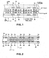
- Figure 1 shows an embodiment of a linear motor which is arranged so that, with respect to an X-Y-Z coordinate system shown in the drawing, a movable element 10 is moved relatively to a stator 20 in an X-axis direction.
- the linear motor comprises first magnet groups (1a - 1d) including first magnets 1a and 1c being arrayed with their polar directions placed periodically in opposite directions or placed in different directions, and second magnets 1b and 1d (permanent magnets) being arrayed with their polar directions placed periodically in opposite directions or placed in different directions and being alternately juxtaposed between the first magnets 1a and 1c.
- the magnets 1a - 1d of the first magnet groups are disposed along the X-axis direction upon one surface of a holding member 7, made of a magnetic or non-magnetic material, and they are integrally connected to each other.
- the design magnetization direction (direction of magnetic flux vector from N-pole to S-pole) of the first magnets 1a and 1c is placed in parallel to the Y-axis direction which is perpendicular to the X-axis direction (movement direction of the movable element 10).
- the design magnetization direction of the second magnets 1b and 1d is parallel to the X-axis direction.
- second magnet groups (5a - 5d) arrayed similarly along the X-axis direction.
- the second magnet groups include third magnets 5a and 5c being arrayed with their polar directions placed periodically in opposite directions or placed in different directions, and fourth magnets 5b and 5d (permanent magnets) being arrayed with their polar directions placed periodically in opposite directions or placed in different directions and being alternately juxtaposed between the third magnets 5a and 5c.
- the design magnetization direction (direction of magnetic flux vector from N-pole to S-pole) of the third magnets 5a and 5c is placed in parallel to the Y-axis direction which is perpendicular to the X-axis direction (movement direction of the movable element 10).
- the design magnetization direction of the fourth magnets 5b and 5d is parallel to the X-axis direction.
- the first magnets 1a and 1c and the third magnets 5a and 5c are placed so that their polar directions (magnetic flux vector from N-pole to S-pole) are oriented in the same direction. Also, as far as design is concerned, the second magnets 1b and 1d and the fourth magnets 5b and 5d are placed so that their polar directions are oriented in opposite directions.
- the movable element 10 of the linear motor comprises first magnet groups 1a - 1d, second magnet groups 5a - 5d and a holding member.
- a stator 20 of the linear motor 20 comprises electromagnetic coils 2a and 2b (coil means), and yokes 3a and 3b for fixedly holding the electromagnetic coils 2a and 2b, respectively.
- the electromagnetic coils 2a and 2b include a coil wound along an X-Z plane.
- a coil central axis 8 is a virtual line that contains a line passing through or substantially passing through the center of the coils 2a and 2b and being perpendicular or substantially perpendicular to the end face of the coil (which is parallel to or substantially parallel to the X-Z plane).
- the polar direction of the coil at the center of the coils 2a and 2b is parallel to or substantially parallel to the coil central axis.
- the yoke 3a is provided at one side of the electromagnetic coil 2a remote from the magnets.
- the yoke 3b is provided at one side of the electromagnetic coil 2b remote from the magnets.
- the plurality of electromagnetic coils 2a fixed to the yoke 3a are disposed with mutual deviations of 90 deg., 180 deg., 270 deg. and 360 deg. in terms of electrical angle.
- the plurality of electromagnetic coils 2b fixed to the yoke 3b are disposed with mutual deviations of 90 deg., 180 deg., 270 deg. and 360 deg. in terms of electrical angle.
- a Lorentz's force (thrust force) is produced between the coil and the magnetic groups 1a - 1d and 5a - 5d at the movable element 10 side, in the X-axis direction (movement direction of the movable element).
- the magnets 1a - 1d and 5a - 5d may be provided at the linear motor stator side, while the electromagnetic coils 2a and 2b may be provided upon the movable element. Further, in place of providing coils 2a and 2b at the opposite sides of the magnets 1a - 1d and 5a - 5d, the magnets 1a - 1d and the magnets 5a - 5d may be disposed separately with respect to the Y-axis direction, and coils 2a (or 2b) may be disposed between them.
- the present invention is applicable also to such linear motor structure.
- the magnetization direction of the first magnets 1a and 1c and the third magnets 5a and 5c in other words, the vector direction extending from N-pole to S-pole, is designed to be parallel to the Y-axis direction (i.e. coil central axis 8).
- the inventor of the subject application has found that, actually, the structure may not exactly follow the design and that the magnetization direction may tilt in an arbitrary direction with respect to the Y-axis direction.
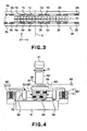
- This embodiment has a structure as shown in Figure 2 that is effective to suppress, reduce or avoid the production of such unwanted force, other than the thrust to the movable element 10.
- the magnetization direction of the magnet 1c has a certain counterclockwise tilt along the X-Y plane, with respect to the design magnetization direction which is parallel to or substantially parallel to the coil central axis 8 (Y-axis direction).
- the magnetization direction of the magnet 5c has a certain clockwise tilt along the X-Y plane, with respect to the design magnetization direction which is parallel to or substantially parallel to the coil central axis 8 (Y-axis direction).
- the magnetization directions of the magnets 1c and 5c have different tilts with respect to the coil central axis 8, or alternatively, they are tilted differently.
- the magnetic flux density distribution in the region where the electromagnetic coil 2a is present and the magnetic flux density distribution in the region where the electromagnetic coil 2b is present can be adjusted to be registered or substantially registered with each other.
- substantial cancellation means reducing the thrust in Y direction or rotational force about the Z-axis to a level that has substantially no influence upon the movement of the movable element 10 in the X-axis direction.
- this embodiment may preferably be structured so that the total sum of tilts of the magnetization directions of the magnets 1c and 5c with respect to the coil central axis 8 becomes approximately null.
- the tilt of the magnetization direction of the magnet 1c with respect to the coil central axis 8 is denoted by ⁇ 1 and the tilt of the magnetization direction of the magnet 5c with respect to the coil central axis 8 is denoted by (- ⁇ 5), preferably the sum of the tilt ⁇ 1 and the tilt - ⁇ 5 is made equal to or approximately equal to zero.
- the adjustment of the magnetization direction of the magnets 1c and 5c with respect to the coil central axis 8 is performed by using an adjusting mechanism (not shown) provided at the holding member 7 or, alternatively, an adjusting member sandwiched between the magnets 1c and 5c, to thereby rotate or tilt at least one of the magnets 1c and 5c about at least one of the X, Y and Z axes.
- the magnets 1a and 5a may preferably be adjusted into a similar relationship.
- Figure 3 shows a second embodiment. This embodiment differs from the first embodiment in that the adjustment of magnetization direction is performed also with regard to a set of the magnets 1b and 5b and a set of the magnets 1d and 5d. Duplicate description of similar structure and function as of the first embodiment will now be omitted.
- the magnetization direction of the magnet 1b has a certain clockwise tilt along the X-Y plane, with respect to the design magnetization direction which is parallel or substantially parallel to a direction (X-axis direction) orthogonal to the coil central axis 8 (Y-axis direction).
- the magnetization direction of the magnet 5d has a certain counterclockwise tilt along the X-Y plane, with respect to the design magnetization direction which is parallel or substantially parallel to a direction (X-axis direction) orthogonal to the coil central axis 8 (Y-axis direction).
- the magnetization directions of the magnets 1b and 5b have different tilts with respect to the coil central axis 8, or alternatively, they are tilted differently.
- the magnetization directions of the magnets 1b and 5b differ from each other, with certain tilts in opposite directions, along the X-Y plane, from a direction parallel to or substantially parallel to the coil central axis 8 (Y-axis direction).
- the magnetic flux density distribution in the region where the electromagnetic coil 2a is present and the magnetic flux density distribution in the region where the electromagnetic coil 2b is present can be adjusted to be registered or substantially registered with each other.
- substantial cancellation means reducing the thrust in Y direction or rotational force about the Z-axis to a level that has substantially no influence upon the movement of the movable element 10 in the X-axis direction.
- this embodiment may preferably be structured so that the total sum of tilts of the magnetization directions of the magnets 1b and 5b with respect to the coil central axis 8 becomes approximately null.
- the tilt of the magnetization direction of the magnet 1b with respect to the coil central axis 8 is denoted by ⁇ 1 and the tilt of the magnetization direction of the magnet 5b with respect to the coil central axis 8 is denoted by (- ⁇ 5), preferably the sum of the tilt ⁇ 1 and the tilt - ⁇ 5 is made equal to or approximately equal to zero.
- the adjustment of the magnetization direction of the magnets 1b and 5b with respect to the coil central axis 8 is performed by using an adjusting mechanism (not shown) provided at the holding member 7 or, alternatively, an adjusting member sandwiched between the magnets 1b and 5b, to thereby rotate or tilt at least one of the magnets 1b and 5b about at least one of the X, Y and Z axes.
- the magnets 1d and 5d may preferably be adjusted into a similar relationship.
- two magnets are disposed along the coil central axis and they are placed with their magnetization directions tilted differently.
- three or more magnets may be disposed along the coil central axis to perform the adjustment for reducing the thrust in the Y direction or rotational force about the Z axis.
- Figure 4 shows a semiconductor device manufacturing exposure apparatus having a stage system, as a wafer stage, in which linear motors M1 and M2 such as described above are incorporated as a driving means.
- This exposure apparatus can be used for manufacture of microdevices, such as semiconductor devices (e.g. semiconductor integrated circuits), micromachines, thin-film magnetic heads, for example, having a fine pattern formed thereon.
- a reticle R original
- a semiconductor wafer W substrate
- exposure light generator term for visible light, ultraviolet light, EUV light, X-rays, electron beam, and charged particle beam, for example
- a projection lens generator term for dioptric lens, catoptric lens, catadioptric lens system, and charged particle lens, for example
- This exposure apparatus has a guide 52 and a linear motor stator 21 fixedly mounted on a base table 51.
- the linear motor stator 21 has multiple-phase electromagnetic coils while a linear motor movable element 11 has permanent magnet groups.
- the linear motor movable element 11 (moving portion 53) is connected to a movable guide 54 (stage). Through the drive of the linear motor M1, the movable guide 54 is moved in a direction normal to the sheet of the drawing.
- the movable portion 53 is supported by static bearing means 55 with reference to the top face of the base table 51, and it is supported by static bearing means 56 with reference to the side face of the guide 52.
- a moving stage 57 which is a stage that straddles the movable guide 54 is supported by static bearing means 58.
- This moving stage 57 is driven by the linear motor M2 like the motor described above.
- the moving stage 57 is moved horizontally as seen in the sheet of the drawing, with reference to the movable guide 54.
- the motion of the moving stage 57 is measured by using a mirror 59 fixedly mounted on the moving stage 57 and an interferometer 60.
- a wafer W (substrate) is held by a chuck that is mounted on the moving stage 57, such that a pattern of the reticle R (original) is transferred in a reduced scale onto different regions of the wafer W in a step-and-repeat or step-and-scan method, by means of a light source 61 and a projection optical system 62.
- linear motor of the present invention is similarly applicable also to an exposure apparatus of the type that a circuit pattern is directly drawn on a semiconductor wafer without using a mask, to thereby expose a resist thereon.
- Step 5 is a flow chart for explaining general procedure for production of semiconductor devices.
- Step 1 is a design process for designing a circuit of a semiconductor device.
- Step 2 is a process for making a mask on the basis of the circuit pattern design.
- Step 3 is a process for preparing a wafer by using a material such as silicon.
- Step 4 is a wafer process which is called a pre-process wherein, by using the thus prepared mask and wafer, a circuit is formed on the wafer in practice, in accordance with lithography.
- Step 5 subsequent to this is an assembling step which is called a post-process wherein the wafer having been processed at step 4 is formed into semiconductor chips.
- This step includes an assembling (dicing and bonding) process and a packaging (chip sealing) process.
- Step 6 is an inspection step wherein an operation check, a durability check an so on, for the semiconductor devices produced by step 5, are carried out. With these processes, semiconductor devices are produced, and they are shipped (step 7).
- the wafer process described above includes an oxidation process for oxidizing the surface of a wafer; a CVD process for forming an insulating film on the wafer surface; an electrode forming process for forming electrodes upon the wafer by vapor deposition; an ion implanting process for implanting ions to the wafer; a resist process for applying a resist (photosensitive material) to the wafer; and an exposure process for printing, by exposure, the circuit pattern of the mask on the wafer through the exposure apparatus described above. Also, it includes a developing process for developing the exposed wafer; an etching process for removing portions other than the developed resist image; and a resist separation process for separating the resist material remaining on the wafer after being subjected to the etching process. By repeating these processes, circuit patterns are superposedly formed on the wafer.
Landscapes
- Physics & Mathematics (AREA)
- Chemical & Material Sciences (AREA)
- Engineering & Computer Science (AREA)
- General Physics & Mathematics (AREA)
- Combustion & Propulsion (AREA)
- Electromagnetism (AREA)
- Power Engineering (AREA)
- Analytical Chemistry (AREA)
- Exposure And Positioning Against Photoresist Photosensitive Materials (AREA)
- Linear Motors (AREA)
- Exposure Of Semiconductors, Excluding Electron Or Ion Beam Exposure (AREA)
Applications Claiming Priority (2)
| Application Number | Priority Date | Filing Date | Title |
|---|---|---|---|
| JP2003035268A JP4194383B2 (ja) | 2003-02-13 | 2003-02-13 | リニアモータ |
| JP2003035268 | 2003-02-13 |
Publications (2)
| Publication Number | Publication Date |
|---|---|
| EP1447902A2 true EP1447902A2 (de) | 2004-08-18 |
| EP1447902A3 EP1447902A3 (de) | 2006-11-08 |
Family
ID=32677610
Family Applications (1)
| Application Number | Title | Priority Date | Filing Date |
|---|---|---|---|
| EP04250763A Withdrawn EP1447902A3 (de) | 2003-02-13 | 2004-02-12 | Linearmotor, Trägersystem und Belichtungssystem mit einem solchen Linearmotor, und Herstellungsmethode |
Country Status (3)
| Country | Link |
|---|---|
| US (2) | US7067942B2 (de) |
| EP (1) | EP1447902A3 (de) |
| JP (1) | JP4194383B2 (de) |
Cited By (2)
| Publication number | Priority date | Publication date | Assignee | Title |
|---|---|---|---|---|
| WO2011047367A1 (en) * | 2009-10-16 | 2011-04-21 | Thorlabs, Inc. | Motorized stage |
| US7965010B2 (en) | 2008-09-03 | 2011-06-21 | Bose Corporation | Linear motor with patterned magnet arrays |
Families Citing this family (25)
| Publication number | Priority date | Publication date | Assignee | Title |
|---|---|---|---|---|
| US6602911B2 (en) * | 2001-11-05 | 2003-08-05 | Cypress Bioscience, Inc. | Methods of treating fibromyalgia |
| JP4227452B2 (ja) * | 2002-12-27 | 2009-02-18 | キヤノン株式会社 | 位置決め装置、及びその位置決め装置を利用した露光装置 |
| US7385679B2 (en) * | 2004-12-29 | 2008-06-10 | Asml Netherlands B.V. | Lithographic apparatus and actuator |
| JP2006211873A (ja) | 2005-01-31 | 2006-08-10 | Canon Inc | 移動体制御装置及び移動体制御方法 |
| US7456935B2 (en) * | 2005-04-05 | 2008-11-25 | Asml Netherlands B.V. | Lithographic apparatus and device manufacturing method utilizing a positioning device for positioning an object table |
| JP2007312516A (ja) * | 2006-05-18 | 2007-11-29 | Canon Inc | 駆動装置、露光装置及びデバイス製造方法 |
| JP2008004647A (ja) | 2006-06-20 | 2008-01-10 | Canon Inc | 位置決め装置、露光装置及びデバイスの製造方法 |
| US8649933B2 (en) | 2006-11-07 | 2014-02-11 | Smartdrive Systems Inc. | Power management systems for automotive video event recorders |
| BRPI0813185B1 (pt) | 2007-07-09 | 2023-12-19 | Clearwater Holdings, Ltd | Máquina eletromagnética giratória |
| EP2340602B1 (de) | 2008-09-26 | 2019-01-02 | Clearwater Holdings, Ltd. | Permanentmagnetisch operierende maschine |
| US8358039B2 (en) * | 2008-10-17 | 2013-01-22 | Massachusetts Institute Of Technology | High-scan rate positioner for scanned probe microscopy |
| JP5370313B2 (ja) * | 2010-08-24 | 2013-12-18 | 株式会社安川電機 | リニアモータ |
| US20120299398A1 (en) * | 2011-05-23 | 2012-11-29 | Nikon Corporation | Motor, design method and manufacturing method of motor, stage device, and exposure apparatus |
| US9083227B2 (en) * | 2011-09-09 | 2015-07-14 | Asml Holding N.V. | Linear motor and lithography arrangement including linear motor |
| US9752968B2 (en) | 2012-12-21 | 2017-09-05 | Luminex Corporation | Rotating shielded magnetic actuator |
| US9636689B2 (en) | 2012-12-21 | 2017-05-02 | Luminex Corporation | Rotating magnetic actuator |
| US10505412B2 (en) | 2013-01-24 | 2019-12-10 | Clearwater Holdings, Ltd. | Flux machine |
| CA2954469C (en) | 2014-07-23 | 2023-03-21 | Clearwater Holdings, Ltd | Flux machine |
| CN104467343B (zh) * | 2014-11-27 | 2017-08-11 | 金陵科技学院 | 一种筒形磁极组合直线发电机 |
| JP7052017B2 (ja) | 2017-09-08 | 2022-04-11 | クリアウォーター ホールディングス,リミテッド | 蓄電を改善するシステム及び方法 |
| WO2019084568A1 (en) | 2017-10-29 | 2019-05-02 | Clearwater Holdings, Ltd. | MODULAR ELECTROMAGNETIC MACHINES AND METHODS OF USE AND MANUFACTURE |
| JP7060995B2 (ja) * | 2018-03-30 | 2022-04-27 | キヤノン株式会社 | ステージ装置、リソグラフィ装置、および物品の製造方法 |
| CN112041748A (zh) | 2018-04-25 | 2020-12-04 | Asml荷兰有限公司 | 管状线性致动器、图案形成装置掩蔽装置和光刻设备 |
| NL2022467B1 (en) * | 2019-01-28 | 2020-08-18 | Prodrive Tech Bv | Position sensor for long stroke linear permanent magnet motor |
| CA3115634A1 (en) * | 2021-04-20 | 2022-10-20 | Rodney HERRING | Charged particle imaging system and use thereof |
Family Cites Families (21)
| Publication number | Priority date | Publication date | Assignee | Title |
|---|---|---|---|---|
| US5684856A (en) | 1991-09-18 | 1997-11-04 | Canon Kabushiki Kaisha | Stage device and pattern transfer system using the same |
| JP3363662B2 (ja) | 1994-05-19 | 2003-01-08 | キヤノン株式会社 | 走査ステージ装置およびこれを用いた露光装置 |
| JP3815750B2 (ja) | 1995-10-09 | 2006-08-30 | キヤノン株式会社 | ステージ装置、ならびに前記ステージ装置を用いた露光装置およびデバイス製造方法 |
| JPH09308218A (ja) | 1996-05-10 | 1997-11-28 | Canon Inc | リニアモータ及びこれを用いたステージ装置や露光装置 |
| JP3548353B2 (ja) | 1996-10-15 | 2004-07-28 | キヤノン株式会社 | ステージ装置およびこれを用いた露光装置ならびにデバイス製造方法 |
| JPH1198811A (ja) | 1997-09-24 | 1999-04-09 | Canon Inc | リニアモータ、これを用いたステージ装置や露光装置、ならびにデバイス製造方法 |
| JP3630964B2 (ja) | 1997-12-26 | 2005-03-23 | キヤノン株式会社 | ステージ装置、およびこれを用いた露光装置ならびにデバイス製造方法 |
| JPH11287880A (ja) | 1998-04-01 | 1999-10-19 | Canon Inc | ステージ装置、およびこれを用いた露光装置ならびにデバイス製造方法 |
| JP3907357B2 (ja) | 1998-11-12 | 2007-04-18 | キヤノン株式会社 | 段差付きコイル製造方法 |
| US6208045B1 (en) * | 1998-11-16 | 2001-03-27 | Nikon Corporation | Electric motors and positioning devices having moving magnet arrays and six degrees of freedom |
| US6104108A (en) * | 1998-12-22 | 2000-08-15 | Nikon Corporation | Wedge magnet array for linear motor |
| US6533083B1 (en) * | 2000-02-15 | 2003-03-18 | Magnetar Technologies, Inc | Eddy current braking apparatus |
| JP4600712B2 (ja) * | 2001-02-09 | 2010-12-15 | 株式会社安川電機 | リニアモータ |
| JP2002325421A (ja) * | 2001-02-23 | 2002-11-08 | Canon Inc | リニアモータ、およびこれを用いたステージ装置、露光装置ならびにデバイス製造方法 |
| US20020149270A1 (en) * | 2001-04-12 | 2002-10-17 | Hazelton Andrew J. | Planar electric motor with two sided magnet array |
| JP2002369492A (ja) * | 2001-06-06 | 2002-12-20 | Hitachi Metals Ltd | 永久磁石及びこれを用いた磁場発生用磁気回路並びにリニアアクチュエータ |
| US6633217B2 (en) * | 2001-06-29 | 2003-10-14 | The Regents Of The University Of California | Inductrack magnet configuration |
| JP2003022960A (ja) | 2001-07-09 | 2003-01-24 | Canon Inc | ステージ装置及びその駆動方法 |
| JP3749882B2 (ja) * | 2001-08-22 | 2006-03-01 | エイエスエムエル ネザランドズ ベスローテン フエンノートシャップ | リソグラフィ装置および前記装置で用いるモータ |
| EP1300932B1 (de) | 2001-10-05 | 2013-12-18 | Canon Kabushiki Kaisha | Linearmotor, Trägersystem und Belichtungssystem mit einem solchen Linearmotor |
| JP4323759B2 (ja) | 2002-05-27 | 2009-09-02 | キヤノン株式会社 | 露光装置およびデバイス製造方法 |
-
2003
- 2003-02-13 JP JP2003035268A patent/JP4194383B2/ja not_active Expired - Fee Related
-
2004
- 2004-02-12 EP EP04250763A patent/EP1447902A3/de not_active Withdrawn
- 2004-02-13 US US10/777,196 patent/US7067942B2/en not_active Expired - Fee Related
-
2005
- 2005-12-01 US US11/290,498 patent/US7348695B2/en not_active Expired - Lifetime
Cited By (3)
| Publication number | Priority date | Publication date | Assignee | Title |
|---|---|---|---|---|
| US7965010B2 (en) | 2008-09-03 | 2011-06-21 | Bose Corporation | Linear motor with patterned magnet arrays |
| WO2011047367A1 (en) * | 2009-10-16 | 2011-04-21 | Thorlabs, Inc. | Motorized stage |
| US8575792B2 (en) | 2009-10-16 | 2013-11-05 | Thorlabs, Inc. | Motorized stage |
Also Published As
| Publication number | Publication date |
|---|---|
| US20040207271A1 (en) | 2004-10-21 |
| JP4194383B2 (ja) | 2008-12-10 |
| EP1447902A3 (de) | 2006-11-08 |
| US7348695B2 (en) | 2008-03-25 |
| JP2004248400A (ja) | 2004-09-02 |
| US7067942B2 (en) | 2006-06-27 |
| US20060082225A1 (en) | 2006-04-20 |
Similar Documents
| Publication | Publication Date | Title |
|---|---|---|
| US7067942B2 (en) | Linear motor, moving stage system, exposure apparatus, and device manufacturing method | |
| US6870284B2 (en) | Linear motor and stage apparatus, exposure apparatus, and device manufacturing method using the same | |
| US7057710B2 (en) | Stage system including fine-motion cable unit, exposure apparatus, and method of manufacturing device | |
| US20100167556A1 (en) | Three degree of movement mover and method for controlling a three degree of movement mover | |
| US7336344B2 (en) | Positioning system, exposure apparatus using the same, and device manufacturing method | |
| KR20100018547A (ko) | 광학 소자 구동 장치, 경통 및 노광 장치 및 디바이스의 제조 방법 | |
| US7656062B2 (en) | Split coil linear motor for z force | |
| US6320645B1 (en) | Stage system and exposure apparatus, and device manufacturing method using the same | |
| JP2004364392A (ja) | リニアモータ、及びこれを備えるステージ装置、露光装置並びにデバイス製造方法 | |
| US7282819B2 (en) | Stage apparatus, exposure apparatus, and device manufacturing method | |
| US7211908B2 (en) | Magnetic floating device | |
| JP2007329435A (ja) | ステージ装置、露光装置及びデバイス製造方法 | |
| US6841956B2 (en) | Actuator to correct for off center-of-gravity line of force | |
| US6844694B2 (en) | Stage assembly and exposure apparatus including the same | |
| US20050211920A1 (en) | Positioning device and method of initializing a positioning device | |
| US7283210B2 (en) | Image shift optic for optical system | |
| US7738114B2 (en) | Exposure apparatus configured to minimize effects of mechanism for measuring stage position on peripheral mechanism and device-manufacturing method | |
| JP2004281654A (ja) | 駆動機構及びそれを用いた露光装置、デバイスの製造方法 | |
| JP4653189B2 (ja) | リニアモータ製造方法 | |
| US7221433B2 (en) | Stage assembly including a reaction assembly having a connector assembly | |
| JP2008172137A (ja) | 位置決め装置および露光装置 | |
| US7193683B2 (en) | Stage design for reflective optics | |
| JP5058546B2 (ja) | 力発生装置およびこれを用いたステージ装置ならびに露光装置 |
Legal Events
| Date | Code | Title | Description |
|---|---|---|---|
| PUAI | Public reference made under article 153(3) epc to a published international application that has entered the european phase |
Free format text: ORIGINAL CODE: 0009012 |
|
| AK | Designated contracting states |
Kind code of ref document: A2 Designated state(s): AT BE BG CH CY CZ DE DK EE ES FI FR GB GR HU IE IT LI LU MC NL PT RO SE SI SK TR |
|
| AX | Request for extension of the european patent |
Extension state: AL LT LV MK |
|
| PUAL | Search report despatched |
Free format text: ORIGINAL CODE: 0009013 |
|
| AK | Designated contracting states |
Kind code of ref document: A3 Designated state(s): AT BE BG CH CY CZ DE DK EE ES FI FR GB GR HU IE IT LI LU MC NL PT RO SE SI SK TR |
|
| AX | Request for extension of the european patent |
Extension state: AL LT LV MK |
|
| 17P | Request for examination filed |
Effective date: 20070508 |
|
| AKX | Designation fees paid |
Designated state(s): DE NL |
|
| 17Q | First examination report despatched |
Effective date: 20111223 |
|
| STAA | Information on the status of an ep patent application or granted ep patent |
Free format text: STATUS: THE APPLICATION HAS BEEN WITHDRAWN |
|
| 18W | Application withdrawn |
Effective date: 20180321 |