EP1447835A2 - Niederdruckentladungslampe - Google Patents
Niederdruckentladungslampe Download PDFInfo
- Publication number
- EP1447835A2 EP1447835A2 EP04002699A EP04002699A EP1447835A2 EP 1447835 A2 EP1447835 A2 EP 1447835A2 EP 04002699 A EP04002699 A EP 04002699A EP 04002699 A EP04002699 A EP 04002699A EP 1447835 A2 EP1447835 A2 EP 1447835A2
- Authority
- EP
- European Patent Office
- Prior art keywords
- low
- base housing
- pressure discharge
- discharge lamp
- lamp according
- Prior art date
- Legal status (The legal status is an assumption and is not a legal conclusion. Google has not performed a legal analysis and makes no representation as to the accuracy of the status listed.)
- Granted
Links
Images

Classifications
-
- B—PERFORMING OPERATIONS; TRANSPORTING
- B09—DISPOSAL OF SOLID WASTE; RECLAMATION OF CONTAMINATED SOIL
- B09B—DISPOSAL OF SOLID WASTE NOT OTHERWISE PROVIDED FOR
- B09B3/00—Destroying solid waste or transforming solid waste into something useful or harmless
-
- B—PERFORMING OPERATIONS; TRANSPORTING
- B09—DISPOSAL OF SOLID WASTE; RECLAMATION OF CONTAMINATED SOIL
- B09B—DISPOSAL OF SOLID WASTE NOT OTHERWISE PROVIDED FOR
- B09B2101/00—Type of solid waste
- B09B2101/02—Gases or liquids enclosed in discarded articles, e.g. aerosol cans or cooling systems of refrigerators
-
- H—ELECTRICITY
- H01—ELECTRIC ELEMENTS
- H01J—ELECTRIC DISCHARGE TUBES OR DISCHARGE LAMPS
- H01J61/00—Gas-discharge or vapour-discharge lamps
- H01J61/02—Details
- H01J61/30—Vessels; Containers
- H01J61/32—Special longitudinal shape, e.g. for advertising purposes
- H01J61/327—"Compact"-lamps, i.e. lamps having a folded discharge path
-
- B—PERFORMING OPERATIONS; TRANSPORTING
- B02—CRUSHING, PULVERISING, OR DISINTEGRATING; PREPARATORY TREATMENT OF GRAIN FOR MILLING
- B02C—CRUSHING, PULVERISING, OR DISINTEGRATING IN GENERAL; MILLING GRAIN
- B02C19/00—Other disintegrating devices or methods
- B02C19/22—Crushing mills with screw-shaped crushing means
-
- B—PERFORMING OPERATIONS; TRANSPORTING
- B30—PRESSES
- B30B—PRESSES IN GENERAL
- B30B9/00—Presses specially adapted for particular purposes
- B30B9/02—Presses specially adapted for particular purposes for squeezing-out liquid from liquid-containing material, e.g. juice from fruits, oil from oil-containing material
-
- H—ELECTRICITY
- H01—ELECTRIC ELEMENTS
- H01J—ELECTRIC DISCHARGE TUBES OR DISCHARGE LAMPS
- H01J5/00—Details relating to vessels or to leading-in conductors common to two or more basic types of discharge tubes or lamps
- H01J5/50—Means forming part of the tube or lamps for the purpose of providing electrical connection to it
- H01J5/54—Means forming part of the tube or lamps for the purpose of providing electrical connection to it supported by a separate part, e.g. base
-
- H—ELECTRICITY
- H01—ELECTRIC ELEMENTS
- H01J—ELECTRIC DISCHARGE TUBES OR DISCHARGE LAMPS
- H01J61/00—Gas-discharge or vapour-discharge lamps
- H01J61/02—Details
- H01J61/30—Vessels; Containers
- H01J61/32—Special longitudinal shape, e.g. for advertising purposes
- H01J61/325—U-shaped lamps
-
- H—ELECTRICITY
- H01—ELECTRIC ELEMENTS
- H01J—ELECTRIC DISCHARGE TUBES OR DISCHARGE LAMPS
- H01J61/00—Gas-discharge or vapour-discharge lamps
- H01J61/02—Details
- H01J61/54—Igniting arrangements, e.g. promoting ionisation for starting
- H01J61/547—Igniting arrangements, e.g. promoting ionisation for starting using an auxiliary electrode outside the vessel
-
- B—PERFORMING OPERATIONS; TRANSPORTING
- B02—CRUSHING, PULVERISING, OR DISINTEGRATING; PREPARATORY TREATMENT OF GRAIN FOR MILLING
- B02C—CRUSHING, PULVERISING, OR DISINTEGRATING IN GENERAL; MILLING GRAIN
- B02C17/00—Disintegrating by tumbling mills, i.e. mills having a container charged with the material to be disintegrated with or without special disintegrating members such as pebbles or balls
- B02C17/16—Mills in which a fixed container houses stirring means tumbling the charge
- B02C2017/165—Mills in which a fixed container houses stirring means tumbling the charge with stirring means comprising more than one agitator
Definitions
- the present invention relates to a low-pressure discharge lamp with a Base housing, a sinuous tubular discharge vessel the end portions of which are attached to an end portion of the base housing are, and a contacting system for electrical contacting the Lamp located on the end section facing away from the discharge vessel of the base housing.
- the present invention further relates to a low-pressure discharge lamp with a base housing, a discharge vessel, the end portions are attached to the base housing and the at least two U-shaped Has sub-elements and an attachment web, or a discharge vessel, the End sections are attached to the base housing and at least three Has U-shaped partial elements and two attachment webs, the attachment web / die Attachment webs for connecting an end section of one of the U-shaped ones Sub-elements with an end section of the next of the U-shaped sub-elements in such a way that a continuous discharge path is formed in the sub-elements, is / are provided.
- Such low-pressure discharge lamps are used in the company OSRAM for example manufactured under the names DULUX D / E, T / E, T / E IN. More specifically, the lamps mentioned above are concerned compact low-pressure discharge lamps with a discharge vessel of at least four straight, parallel tubes that are in a polygon arranged and by cross connections at or near the end portions the straight pipes into a simply coherent and gastight discharge path are connected.
- a low-pressure discharge lamp is known from patent specification EP 1 217 645 known in the center of the straight tubes of the discharge vessel formed cylindrical cavity parallel to the straight one Pipe-running metal coil spring is arranged around the ignition voltage to humiliate and at the same time the light that is inward into the of the straight tubes and the cross connections of the discharge vessel formed cavity is emitted, pass with little disability allow.
- a fluorescent lamp is known from WO 01/87019, in which an ignition aid on the one hand connected to the base and on the other hand in shape a spring with one leg of the discharge vessel without an electrode in Facility is located.
- the object of the present invention is to overcome the disadvantages of State of the art to eliminate and a lamp with reduced ignition voltage provide for the lamp luminous flux from the discharge vessel is not affected. Furthermore, the lamp according to the invention should have a low Effort can be assembled.
- this object is achieved with a low-pressure discharge lamp of the type described above with base housing, discharge vessel and contacting system through an electrically conductive section with electrical Conclusion about a section of the discharge vessel or about that Entire discharge vessel loosened in the base housing, this conclusion electrically with the contacting system (electrode holder or contact pin) communicates.
- This measure allows the ignition voltage reduce the lamp, preferably if this is at high frequency AC voltage ( ⁇ 20 kHz), such as from an electronic Ballast provided, operated.
- the electrically conductive section is preferably a wire, whereby with little effort and without affecting the luminous flux of the lamp the ignition voltage can be reduced.
- the wire is preferably self-contained and with the electrode holder (one of the four power supply wires or one with the lamp holder connected contact pins) electrically connected.
- the electrode holder one of the four power supply wires or one with the lamp holder connected contact pins
- the reduction in ignition voltage is generally the closer the wire is to the discharge vessel, the higher, whereby here the ends of the glass tubes forming the discharge vessel are meant are that protrude into the base housing for attachment.
- the distance between the wire and the glass tubes is the distance between the Plane that is formed by the electrode coils and the plane that is formed by the wire ring.
- the plane is perpendicular to Lamp longitudinal axis meant. The smaller this distance, the larger the ignition voltage reduction reached.
- the wire can also be in a "serpentine" i.e. times inside and times on the outside of the discharge tube around the lamp.
- a metal ring for example, can be used instead of a wire in the form of a washer, inserted into the lamp base and is contacted with a power supply.
- a conductive layer in the form of a metal foil such as. an aluminum foil, or in the form of an electrically conductive Powder, preferably iron powder, can be provided, which in the Putty of the base housing is embedded.
- This can also be electrically conductive Powder is sprinkled on the putty of the base housing before heating his.
- the discharge vessel has two, preferably three U-shaped partial elements, whose end sections with one or two attachment webs to form a coherent Discharge path are connected.
- the cross section of these attachment webs is with regard to the tube diameter of the discharge vessel optimized so that a minimum ignition voltage is required to ignite the lamp is.
- the ignition voltage can be adjusted by approaching the two ends of the lamp also lower.
- the present invention is based on arbitrarily coiled tubular discharge vessels for low-pressure discharge lamps, in particular compact fluorescent lamps, applicable, preferably on two or three U-shaped Partial elements existing discharge vessels, especially if they be operated on ballasts with a frequency ⁇ 20 kHz.
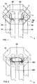
- FIG. 1 schematically shows a partial section of a low-pressure discharge lamp according to the invention in perspective view, while Fig. 4 is the bottom view of the low-pressure discharge lamp with respect to the illustration in FIG. 1.
- This type of low-pressure discharge lamp shown has a discharge vessel 2 made of glass, the six parallel to each other in their longitudinal directions arranged tubes 2a - 2f and that at an end portion of a base housing 10 is provided (see Fig. 1).
- the tubes 2a - 2f together form with cross connections 4A, 4B, 4C and extensions 3A, 3B (see 3, 4) a coherent discharge path.
- the inner wall of the discharge vessel 2 is provided with a phosphor coating.
- the Tubes 2c and 2d as well as tubes 2e and 2f are each one of the in Fig. 4 shown cross-connection 4A, 4B, 4C connected to each other.
- the Cross connections 4A, 4B, 4C are located at the end portions of the tubes 2a - 2f, which are opposite to the end section of the tubes in the base housing are provided.
- the pipes 2b and 2c and 2d and 2e are on the end portions in the base housing 10 through the attachment webs 3A and 3B (see Fig. 4) connected.
- Two tubes arranged side by side, i.e. the tubes 2b and 2c, 2d and 2e and 2a and 2f form the corners of one preferably equilateral triangle.
- the base housing 10 has on its opposite to the discharge vessel 2 End section a contact system, not shown, that makes contact from the electrode holders 6, 7 to the outside and is preferably designed as a pin base.
- electrically conductive wire 5 adjacent to the inner circumference of the base housing 10 to the plaster putty or inserted into it.
- the wire is in arranged in such a way that there is essentially an electrical Forms the end of the discharge vessel 2.
- the wire 5 has a connecting section 5A, via which the latter is connected to one of the electrode holders 6, 7 is electrically connected, and that with the opposite end portion 5B of the wire is in contact.
- the invention is not limited to but the connecting portion 5A and the end portion 5B can alternatively be spaced apart, the inventive Effect is also noted.
- the second embodiment according to the present invention is shown in Fig. 2 and in contrast to the wire 5 of the first embodiment a wire 50 on the inner circumference of the tubes of the Discharge vessel 2 is provided.
- the wire 50 has one on an electrode holder adjacent connecting portion 50A and an end portion 50B that is in contact with the connecting portion 50A.
- the invention is not limited to this, but the connecting section 50A and end portion 50B may alternatively be different from each other be spaced apart, the effect according to the invention also being noted is.
- the assembly can be compared to integrated socket Simplify ignition aids according to the prior art.
- the present invention is not for use with 6-tube lamps limited, but can also be used for low-pressure discharge lamps with 4 tubes, such as the low-pressure discharge lamp OSRAM DULUX D / E used, or those with 8 or with more pipes of the number n.
- 4 tubes such as the low-pressure discharge lamp OSRAM DULUX D / E used, or those with 8 or with more pipes of the number n.
- n / 2 cross connections and (n / 2) -1 attachment webs are provided.
- the wires 5 and 50 respectively in the same way outside the tubes of the discharge vessel or inside provided by these.
- the present invention is also for lowering the ignition voltage successfully applicable if further power supplies, for example to Heating up an amalgam with the lamp already attached.
- wire ring 5 or 50 in a low-pressure discharge lamp instead of the wire ring 5 or 50 in a low-pressure discharge lamp according to the invention according to the third embodiment electrically conductive powder introduced into the base cement of the base housing 10 and contacted with a power supply wire.
- a power supply wire For example 15% iron powder can be placed in the base cement.
- a low-pressure discharge lamp according to the first embodiment, electrically conductive Powder, preferably iron powder, on the base putty before heating sprinkled.
- the powder is in contact with a power supply wire contacted.
- one could Reduction in the ignition voltage can be found.
- the low pressure discharge lamp according to the fifth embodiment is instead of the powder in the third and fourth embodiments an electrically conductive layer on the inside of the base housing provided and provided with a power supply.
- an electrically conductive layer on the inside of the base housing provided and provided with a power supply.
- 3A and 3B serve to illustrate a sixth exemplary embodiment according to the present invention.
- Fig. 3A the tubes 2b and 2c and their foot connection to the Attachment web 3A is shown schematically.
- the pipes are the same 2d and 2e via the connecting web 3B and the corresponding pipes Low-pressure discharge lamps connected to n tubes.
- 3B shows one Enlarged view of the cross section of the attachment web 3A in the sectional plane Q in Fig. 3A.
- An increase in the cross section of the attachment webs 3A leads to a reduction in the voltage required to ignite the lamp. For example, with an increase in the cross-section of the web from 9 to 10 mm 2 to approximately 24 mm 2, an ignition voltage reduction of approximately 20 V per attachment web was found.
- the inventor attributes this effect to the fact that the mercury vapor after starting the lamp with larger cross-sectional areas of the Attachment webs can distribute faster in the lamp. On the other hand, the Luminous flux is not affected even by the cross-section of the connecting web.
- the temperature at the base housing is due to the lower wall losses in the area of enlarged attachment webs 3A, 3B about 5 ° C. lower than with standard lamps.
- the large web diameter can, for example, by blowing in a Blow molding can be realized.
- Large wall thicknesses of the discharge tubes can lead to processing problems because of the creation of the web opening a relatively large amount of glass needs to be removed.
- This glass material forms a bead around the attachment web, which causes the gap the pipes 2b and 2c and 2d and 2e must be enlarged. That can cause the end portions of the tubes 2a and 2f in which the electrodes are housed, which makes these tubes the ends of the discharge path form, compared to lamps without an enlarged cross section of the Attachment webs have a reduced distance.
- tubes 2a and 2f also influence the ignition voltage of the lamp, so that when the ignition voltage is reduced by an increase the cross-section of the attachment web is to be taken into account.
- Advantageous values for the web cross section are in the range from 19 to 29 mm 2 , preferably in the range from 22 to 25 mm 2 .
- This widening of the cross-section at the attachment webs reduces the voltage required to transport the initial charge wave from one electrode to the other along the inside of the discharge tubes, since each constriction along the inside of the tubes represents an obstacle for this charge wave.
- the distance between the ends of the tubes 2a and 2f can decrease from the standard 2.3 mm to 1.8 to 0.7 mm. The inventor assumes that with a smaller distance between the electrodes, which are arranged in the ends of the tubes 2a and 2f, the electron avalanche is more easily triggered by the electrodes to the piston wall. This can further lower the required ignition voltage.
- the sixth embodiment is not isolated from the other embodiments consider. So in a low pressure discharge lamp according to the invention in addition to the larger cross sections of the attachment webs one or more devices for reducing the ignition voltage of the first to fifth exemplary embodiments can be provided, preferably the wires 5 or 50 from the first and second embodiments. With these combinations, the wire can lower the Trigger ignition voltage by approximately 100 V while the land extension results in a reduction in the ignition voltage of approximately 40 V.
- a low-pressure discharge lamp with a base housing is thus described, a discharge vessel whose end portions at an end portion of the base housing are attached, and a contacting system for electrical contacting of the lamp, which is located on the discharge vessel facing away end portion of the base housing, wherein a conductive section is provided which is connected to the contacting system in is electrically connected and adjacent to the discharge vessel in the base housing is arranged in such a way that an electrical Conclusion is formed around the discharge vessel.
- the cross section of attachment webs between tubes of the discharge vessel increases, which also increases the speed of the light starting current elevated.
Landscapes
- Engineering & Computer Science (AREA)
- Environmental & Geological Engineering (AREA)
- Mechanical Engineering (AREA)
- Food Science & Technology (AREA)
- Physics & Mathematics (AREA)
- Chemical & Material Sciences (AREA)
- Dispersion Chemistry (AREA)
- Thermal Sciences (AREA)
- Discharge Lamps And Accessories Thereof (AREA)
- Common Detailed Techniques For Electron Tubes Or Discharge Tubes (AREA)
- Vessels And Coating Films For Discharge Lamps (AREA)
Abstract
Description
- Fig. 1
- einen schematischen Teilschnitt einer erfindungsgemäßen Niederdruckentladungslampe entsprechend dem ersten Ausführungsbeispiel,
- Fig. 2
- einen schematischen Teilschnitt einer erfindungsgemäßen Niederdruckentladungslampe entsprechend dem zweiten Ausführungsbeispiel,
- Fig. 3A und 3B
- eine schematische Darstellung des sechsten Ausführungsbeispiels, und
- Fig. 4
- eine Veranschaulichung der Struktur der Entladungsgefäße entsprechend der vorliegenden Erfindung.
- 2
- Entladungsgefäß
- 2a - 2f
- Rohre
- 3A, 3B
- Ansetzstege
- 4A - 4C
- Querverbindungen
- 5
- Draht
- 5A
- Verbindungsabschnitt
- 5B
- Endabschnitt
- 6, 7
- Elektrodenhalterungen
- 10
- Sockelgehäuse
- 50
- Draht
- 50A
- Verbindungsabschnitt
- 50B
- Endabschnitt
Claims (16)
- Niederdruckentladungslampe mit einem Sockelgehäuse (10), einem gewundenen rohrförmigen Entladungsgefäß (2), dessen Endabschnitte an einem Endabschnitt des Sockelgehäuses befestigt sind, und einem Kontaktierungssystem zur elektrischen Kontaktierung der Lampe, das sich an dem vom Entladungsgefäß abgewandten Endabschnitt des Sockelgehäuses (10) befindet, gekennzeichnet durch einen leitfähigen Abschnitt (5, 50), der mit dem Kontaktierungssystem in elektrischer Verbindung steht und benachbart zum Entladungsgefäß (2) im Sockelgehäuse (10) in einer solchen Weise angeordnet ist, dass ein elektrischer Schluss um zumindest einen Teil des Entladungsgefäßes (2) gebildet wird.
- Niederdruckentladungslampe nach Anspruch 1, wobei der elektrisch leitfähige Abschnitt einen Draht (5, 50) aufweist.
- Niederdruckentladungslampe nach Anspruch 2, wobei der Draht (5) zumindest abschnittsweise am Innenumfang des Sockelgehäuses (10) vorgesehen ist.
- Niederdruckentladungslampe nach Anspruch 2 oder 3, wobei der Draht (50) zumindest abschnittsweise am Innenumfang der das Entladungsgefäß (2) bildenden Entladungsrohre (2a - 2f) vorgesehen ist.
- Niederdruckentladungslampe nach Anspruch 2 oder 3, wobei das Entladungsgefäß (2) zumindest zwei Rohre (2a - 2f) aufweist, zwischen denen sich der Draht (50) befindet.
- Niederdruckentladungslampe nach Anspruch 3 oder 4, wobei der Draht (5, 50) einseitig mit dem Kontaktierungssystem in elektrischer Verbindung steht.
- Niederdruckentladungslampe nach Anspruch 5, wobei der Draht (5, 50) in sich geschlossen ist.
- Niederdruckentladungslampe nach Anspruch 1, wobei der elektrisch leitfähige Abschnitt eine leitfähige Schicht an der Innenseite des Sockelgehäuses (10) aufweist.
- Niederdruckentladungslampe nach Anspruch 8, wobei die leitfähige Schicht eine Metallfolie, vorzugsweise Aluminiumfolie, aufweist.
- Niederdruckentladungslampe nach Anspruch 1, wobei der elektrisch leitfähige Abschnitt ein elektrisch leitfähiges Pulver in der Kittmasse des Sockelgehäuses (10) aufweist.
- Niederdruckentladungslampe nach Anspruch 10, wobei das Pulver Eisenpulver ist, das in die Grundmasse des Sockelgehäuses (10) gemischt wurde.
- Niederdruckentladungslampe nach Anspruch 10, wobei das Pulver Eisenpulver ist, das auf die Grundmasse des Sockelgehäuses (10) vor dem Aufheizen aufgestreut wurde.
- Niederdruckentladungslampe nach einem der Ansprüche 8 bis 12, wobei der leitfähige Abschnitt mit einem Kontakt des Kontaktierungssystem in elektrischer Verbindung steht.
- Niederdruckentladungslampe nach einem der vorhergehenden Ansprüche, wobei das Entladungsgefäß (2) zumindest drei U-förmige Teilelemente (2a, 2b, 4A; 2c, 2d, 4B; 2e, 2f, 4C) hat und jeweils ein Ansetzsteg (3A, 3B) zur Verbindung von einem Endabschnitt eines der U-förmigen Teilelemente mit einem Endabschnitt des nächsten der U-förmigen Teilelemente in einer solchen Weise, dass ein zusammenhängender Entladungsweg in den Teilelementen gebildet wird, vorgesehen ist, und wobei die Querschnittsfläche der Ansetzstege (3A, 3B) maximal ausgeführt ist, um die Zündspannung der Lampe zu minimieren.
- Niederdruckentladungslampe nach Anspruch 14, wobei das Entladungsgefäß drei U-förmige Teilelemente und zwei Ansetzstege (3A, 3B) aufweist.
- Niederdruckentladungslampe mit einem Sockelgehäuse (10), einem Entladungsgefäß (2), dessen Endabschnitte am Sockelgehäuse befestigt sind und das zumindest zwei U-förmige Teilelemente (2a, 2b, 4A; 2c, 2d, 4B) und einem Ansetzsteg (3A) hat, oder einem Entladungsgefäß (2), dessen Endabschnitte am Sockelgehäuse befestigt sind und das zumindest drei U-förmige Teilelemente (2a, 2b, 4A; 2c, 2d, 4B; 2e, 2f, 4C) und zwei Ansetzstegen (3A, 3B) hat, wobei der Ansetzsteg/die Ansetzstege zur Verbindung von einem Endabschnitt eines der U-förmigen Teilelemente mit einem Endabschnitt des nächsten der U-förmigen Teilelemente in einer solchen Weise, dass ein zusammenhängender Entladungsweg in den Teilelementen gebildet wird, vorgesehen ist/sind, dadurch gekennzeichnet, dass die Querschnittsfläche des Ansetzsteges (3A, 3B) derart maximiert ist, dass die Zündspannung der Lampe minimiert ist.
Priority Applications (1)
| Application Number | Priority Date | Filing Date | Title |
|---|---|---|---|
| EP12180308A EP2528084A3 (de) | 2003-02-17 | 2004-02-06 | Niederdruckentladungslampe |
Applications Claiming Priority (2)
| Application Number | Priority Date | Filing Date | Title |
|---|---|---|---|
| DE10306584 | 2003-02-17 | ||
| DE10306584A DE10306584A1 (de) | 2003-02-17 | 2003-02-17 | Niederdruckentladungslampe |
Related Child Applications (1)
| Application Number | Title | Priority Date | Filing Date |
|---|---|---|---|
| EP12180308.4 Division-Into | 2012-08-13 |
Publications (3)
| Publication Number | Publication Date |
|---|---|
| EP1447835A2 true EP1447835A2 (de) | 2004-08-18 |
| EP1447835A3 EP1447835A3 (de) | 2010-10-06 |
| EP1447835B1 EP1447835B1 (de) | 2013-04-03 |
Family
ID=32668097
Family Applications (2)
| Application Number | Title | Priority Date | Filing Date |
|---|---|---|---|
| EP12180308A Withdrawn EP2528084A3 (de) | 2003-02-17 | 2004-02-06 | Niederdruckentladungslampe |
| EP04002699A Expired - Lifetime EP1447835B1 (de) | 2003-02-17 | 2004-02-06 | Niederdruckentladungslampe |
Family Applications Before (1)
| Application Number | Title | Priority Date | Filing Date |
|---|---|---|---|
| EP12180308A Withdrawn EP2528084A3 (de) | 2003-02-17 | 2004-02-06 | Niederdruckentladungslampe |
Country Status (8)
| Country | Link |
|---|---|
| US (1) | US7030564B2 (de) |
| EP (2) | EP2528084A3 (de) |
| JP (1) | JP4532132B2 (de) |
| KR (1) | KR101052639B1 (de) |
| CN (1) | CN1326195C (de) |
| CA (1) | CA2458891A1 (de) |
| DE (1) | DE10306584A1 (de) |
| TW (1) | TWI331354B (de) |
Citations (5)
| Publication number | Priority date | Publication date | Assignee | Title |
|---|---|---|---|---|
| DE8337107U1 (de) | 1983-12-23 | 1985-05-30 | Patent-Treuhand-Gesellschaft für elektrische Glühlampen mbH, 8000 München | Sockel fuer eine niederdruck-entladungslampe |
| DE3642413A1 (de) | 1986-12-11 | 1988-06-23 | Juerg Nigg | Verfahren zur erhoehung der zuendwilligkeit von entladungslampen, zuendhilfeanordnung und entladungslampe mit zuendhilfe |
| JPH07320695A (ja) | 1994-01-31 | 1995-12-08 | Toshiba Lighting & Technol Corp | コンパクト形けい光ランプおよびランプ点灯装置ならびにこのランプを用いた照明装置 |
| EP0918352A1 (de) | 1997-06-11 | 1999-05-26 | Toshiba Lighting & Technology Corporation | Leuchtstofflampe, kompakte selbstbeschwerde leuchtstofflampe und beleuchtungseinrichtung |
| US6051930A (en) | 1998-04-01 | 2000-04-18 | General Electric Company | Extended wire connector for starting compact fluorescent lamp system |
Family Cites Families (12)
| Publication number | Priority date | Publication date | Assignee | Title |
|---|---|---|---|---|
| DE8131006U1 (de) * | 1981-10-23 | 1983-04-07 | Patent-Treuhand-Gesellschaft für elektrische Glühlampen mbH, 8000 München | Elektrische lampe |
| US4508993A (en) * | 1981-11-25 | 1985-04-02 | General Electric Company | Fluorescent lamp without ballast |
| DD205772A1 (de) * | 1982-02-16 | 1984-01-04 | Reinhard Butz | Niederdruckgasentladungslampe, insbesondere leuchtstofflampe kleiner leistung |
| US4853591A (en) * | 1983-11-25 | 1989-08-01 | Patent Treuhand Gesellschaft Fur Elektrische Gluhlampen Mbh | Multiple-tube compact low-pressure discharge fluorescent lamp |
| JPH0770303B2 (ja) * | 1986-03-19 | 1995-07-31 | 松下電子工業株式会社 | 放電灯 |
| JPH0430764Y2 (de) * | 1987-10-30 | 1992-07-24 | ||
| US6064152A (en) | 1998-06-17 | 2000-05-16 | General Electric Company | Electrically conductive cylinder for improved starting of compact fluorescent lamp systems |
| JP2001202921A (ja) * | 2000-01-18 | 2001-07-27 | Matsushita Electric Ind Co Ltd | 蛍光ランプおよび照明器具 |
| WO2001087019A1 (en) | 2000-05-11 | 2001-11-15 | General Electric Company | Starting aid for fluorescent lamps |
| DE10063958A1 (de) * | 2000-12-20 | 2002-06-27 | Patent Treuhand Ges Fuer Elektrische Gluehlampen Mbh | Kompakte Niederdruckentladungslampe mit Zündhilfe |
| KR100580117B1 (ko) * | 2004-09-03 | 2006-05-12 | 에스티마이크로일렉트로닉스 엔.브이. | 반도체 메모리 소자의 소자 분리막 형성방법 |
| JP7070303B2 (ja) * | 2018-10-04 | 2022-05-18 | 三菱電機株式会社 | 半導体装置 |
-
2003
- 2003-02-17 DE DE10306584A patent/DE10306584A1/de not_active Withdrawn
-
2004
- 2004-02-06 EP EP12180308A patent/EP2528084A3/de not_active Withdrawn
- 2004-02-06 EP EP04002699A patent/EP1447835B1/de not_active Expired - Lifetime
- 2004-02-12 TW TW093103315A patent/TWI331354B/zh not_active IP Right Cessation
- 2004-02-16 KR KR1020040009934A patent/KR101052639B1/ko not_active Expired - Fee Related
- 2004-02-17 CA CA002458891A patent/CA2458891A1/en not_active Abandoned
- 2004-02-17 JP JP2004040269A patent/JP4532132B2/ja not_active Expired - Fee Related
- 2004-02-17 US US10/778,156 patent/US7030564B2/en not_active Expired - Fee Related
- 2004-02-17 CN CNB2004100387970A patent/CN1326195C/zh not_active Expired - Lifetime
Patent Citations (5)
| Publication number | Priority date | Publication date | Assignee | Title |
|---|---|---|---|---|
| DE8337107U1 (de) | 1983-12-23 | 1985-05-30 | Patent-Treuhand-Gesellschaft für elektrische Glühlampen mbH, 8000 München | Sockel fuer eine niederdruck-entladungslampe |
| DE3642413A1 (de) | 1986-12-11 | 1988-06-23 | Juerg Nigg | Verfahren zur erhoehung der zuendwilligkeit von entladungslampen, zuendhilfeanordnung und entladungslampe mit zuendhilfe |
| JPH07320695A (ja) | 1994-01-31 | 1995-12-08 | Toshiba Lighting & Technol Corp | コンパクト形けい光ランプおよびランプ点灯装置ならびにこのランプを用いた照明装置 |
| EP0918352A1 (de) | 1997-06-11 | 1999-05-26 | Toshiba Lighting & Technology Corporation | Leuchtstofflampe, kompakte selbstbeschwerde leuchtstofflampe und beleuchtungseinrichtung |
| US6051930A (en) | 1998-04-01 | 2000-04-18 | General Electric Company | Extended wire connector for starting compact fluorescent lamp system |
Also Published As
| Publication number | Publication date |
|---|---|
| JP4532132B2 (ja) | 2010-08-25 |
| EP1447835A3 (de) | 2010-10-06 |
| DE10306584A1 (de) | 2004-08-26 |
| US7030564B2 (en) | 2006-04-18 |
| KR20040074930A (ko) | 2004-08-26 |
| EP2528084A2 (de) | 2012-11-28 |
| EP2528084A3 (de) | 2013-03-20 |
| US20040160182A1 (en) | 2004-08-19 |
| JP2004253387A (ja) | 2004-09-09 |
| EP1447835B1 (de) | 2013-04-03 |
| CN1551288A (zh) | 2004-12-01 |
| CA2458891A1 (en) | 2004-08-17 |
| KR101052639B1 (ko) | 2011-07-28 |
| TWI331354B (en) | 2010-10-01 |
| CN1326195C (zh) | 2007-07-11 |
| TW200421404A (en) | 2004-10-16 |
Similar Documents
| Publication | Publication Date | Title |
|---|---|---|
| DE19718395C1 (de) | Leuchtstofflampe und Verfahren zu ihrem Betrieb | |
| EP0895653B1 (de) | Elektrische strahlungsquelle und bestrahlungssystem mit dieser strahlungsquelle | |
| DE69804192T2 (de) | Hochdruckentladungslampe mit uv-verstärker | |
| DE3106892A1 (de) | Leuchtstofflampenanordnung und verfahren zum herstellen derselben | |
| DE69903782T2 (de) | Einheit mit einer kurzbogen-entladungslampe mit anlaufantenne | |
| EP0451647B1 (de) | Hochdruckentladungslampe und Verfahren zu ihrer Herstellung | |
| EP1088335B1 (de) | Entladungslampe mit sockel | |
| EP1506567A2 (de) | Dielektrische barriere-entladungslampe mit sockel | |
| EP1334510B1 (de) | Dielektrische barrieren-entladungslampe | |
| EP1276137B1 (de) | Dielektrische Barrieren-Entladungslampe mit Zündhilfe | |
| DE10331510A1 (de) | Kurzbogen-Entladungslampe sowie Lichtquellenvorrichtung | |
| DE4229894B4 (de) | Koppelvorrichtung für die Speisung von Mikrowellenenergie zur Erregung elektrodenloser Lampen | |
| DE69103912T2 (de) | Einseitige Metalldampfentladungslampe. | |
| DE2118828A1 (de) | Hochdruck-Natriumdampf-Entladungslampe | |
| DE3320919C2 (de) | ||
| WO2013017304A1 (de) | Hochdruckentladungslampe mit zündhilfe | |
| EP1447835A2 (de) | Niederdruckentladungslampe | |
| DE19911727A1 (de) | Natriumhochdrucklampe mit Zündhilfe | |
| EP1519407A2 (de) | UV-Strahler mit rohrförmigem Entladungsgefäss | |
| DE10312720A1 (de) | Dielektrische Barriere-Entladungslampe mit Quetschdichtung | |
| EP2529389A1 (de) | Hochdruckentladungslampe mit kapazitiver zündhilfe | |
| DE69707350T2 (de) | Elektrodenanordnung für Natrium-Hochdruckentladungslampe und deren Herstellungsverfahren | |
| DE19741668A1 (de) | Entladungslampe | |
| DE212010000116U1 (de) | Hochdruckentladungslampe mit Zündhilfe | |
| EP4113579A2 (de) | Hochdruckentladungslampe, insbesondere natriumdampf-hoch-drucklampe, mit verbesserter zündfähigkeit |
Legal Events
| Date | Code | Title | Description |
|---|---|---|---|
| PUAI | Public reference made under article 153(3) epc to a published international application that has entered the european phase |
Free format text: ORIGINAL CODE: 0009012 |
|
| AK | Designated contracting states |
Kind code of ref document: A2 Designated state(s): AT BE BG CH CY CZ DE DK EE ES FI FR GB GR HU IE IT LI LU MC NL PT RO SE SI SK TR |
|
| AX | Request for extension of the european patent |
Extension state: AL LT LV MK |
|
| RIC1 | Information provided on ipc code assigned before grant |
Ipc: H01J 61/32 20060101ALI20100720BHEP Ipc: H01J 61/54 20060101AFI20040503BHEP Ipc: H01J 61/70 20060101ALI20100720BHEP Ipc: H01J 5/54 20060101ALI20100720BHEP |
|
| PUAL | Search report despatched |
Free format text: ORIGINAL CODE: 0009013 |
|
| AK | Designated contracting states |
Kind code of ref document: A3 Designated state(s): AT BE BG CH CY CZ DE DK EE ES FI FR GB GR HU IE IT LI LU MC NL PT RO SE SI SK TR |
|
| AX | Request for extension of the european patent |
Extension state: AL LT LV MK |
|
| 17P | Request for examination filed |
Effective date: 20110221 |
|
| 17Q | First examination report despatched |
Effective date: 20110426 |
|
| AKX | Designation fees paid |
Designated state(s): DE FR GB HU IT NL |
|
| GRAP | Despatch of communication of intention to grant a patent |
Free format text: ORIGINAL CODE: EPIDOSNIGR1 |
|
| RAP1 | Party data changed (applicant data changed or rights of an application transferred) |
Owner name: OSRAM AG |
|
| RIN1 | Information on inventor provided before grant (corrected) |
Inventor name: HILSCHER, ACHIM Inventor name: NOLL, THOMAS |
|
| GRAS | Grant fee paid |
Free format text: ORIGINAL CODE: EPIDOSNIGR3 |
|
| RAP1 | Party data changed (applicant data changed or rights of an application transferred) |
Owner name: OSRAM GMBH |
|
| GRAA | (expected) grant |
Free format text: ORIGINAL CODE: 0009210 |
|
| AK | Designated contracting states |
Kind code of ref document: B1 Designated state(s): DE FR GB HU IT NL |
|
| REG | Reference to a national code |
Ref country code: GB Ref legal event code: FG4D Free format text: NOT ENGLISH |
|
| RAP2 | Party data changed (patent owner data changed or rights of a patent transferred) |
Owner name: OSRAM GMBH |
|
| REG | Reference to a national code |
Ref country code: DE Ref legal event code: R096 Ref document number: 502004014089 Country of ref document: DE Effective date: 20130529 |
|
| REG | Reference to a national code |
Ref country code: NL Ref legal event code: VDEP Effective date: 20130403 |
|
| REG | Reference to a national code |
Ref country code: DE Ref legal event code: R081 Ref document number: 502004014089 Country of ref document: DE Owner name: OSRAM GMBH, DE Free format text: FORMER OWNER: OSRAM GMBH, 81543 MUENCHEN, DE Effective date: 20130822 Ref country code: DE Ref legal event code: R081 Ref document number: 502004014089 Country of ref document: DE Owner name: OSRAM GMBH, DE Free format text: FORMER OWNER: PATENT-TREUHAND-GESELLSCHAFT FUER ELEKTRISCHE GLUEHLAMPEN MBH, 81543 MUENCHEN, DE Effective date: 20130408 Ref country code: DE Ref legal event code: R081 Ref document number: 502004014089 Country of ref document: DE Owner name: LEDVANCE GMBH, DE Free format text: FORMER OWNER: OSRAM GMBH, 81543 MUENCHEN, DE Effective date: 20130822 Ref country code: DE Ref legal event code: R081 Ref document number: 502004014089 Country of ref document: DE Owner name: LEDVANCE GMBH, DE Free format text: FORMER OWNER: PATENT-TREUHAND-GESELLSCHAFT FUER ELEKTRISCHE GLUEHLAMPEN MBH, 81543 MUENCHEN, DE Effective date: 20130408 |
|
| PG25 | Lapsed in a contracting state [announced via postgrant information from national office to epo] |
Ref country code: NL Free format text: LAPSE BECAUSE OF FAILURE TO SUBMIT A TRANSLATION OF THE DESCRIPTION OR TO PAY THE FEE WITHIN THE PRESCRIBED TIME-LIMIT Effective date: 20130403 |
|
| PLBE | No opposition filed within time limit |
Free format text: ORIGINAL CODE: 0009261 |
|
| STAA | Information on the status of an ep patent application or granted ep patent |
Free format text: STATUS: NO OPPOSITION FILED WITHIN TIME LIMIT |
|
| 26N | No opposition filed |
Effective date: 20140106 |
|
| REG | Reference to a national code |
Ref country code: DE Ref legal event code: R097 Ref document number: 502004014089 Country of ref document: DE Effective date: 20140106 |
|
| REG | Reference to a national code |
Ref country code: HU Ref legal event code: AG4A Ref document number: E019060 Country of ref document: HU |
|
| PGFP | Annual fee paid to national office [announced via postgrant information from national office to epo] |
Ref country code: HU Payment date: 20140228 Year of fee payment: 11 Ref country code: FR Payment date: 20140219 Year of fee payment: 11 |
|
| GBPC | Gb: european patent ceased through non-payment of renewal fee |
Effective date: 20140206 |
|
| PG25 | Lapsed in a contracting state [announced via postgrant information from national office to epo] |
Ref country code: GB Free format text: LAPSE BECAUSE OF NON-PAYMENT OF DUE FEES Effective date: 20140206 |
|
| REG | Reference to a national code |
Ref country code: FR Ref legal event code: ST Effective date: 20151030 |
|
| PG25 | Lapsed in a contracting state [announced via postgrant information from national office to epo] |
Ref country code: HU Free format text: LAPSE BECAUSE OF NON-PAYMENT OF DUE FEES Effective date: 20150207 |
|
| PG25 | Lapsed in a contracting state [announced via postgrant information from national office to epo] |
Ref country code: FR Free format text: LAPSE BECAUSE OF NON-PAYMENT OF DUE FEES Effective date: 20150302 |
|
| PG25 | Lapsed in a contracting state [announced via postgrant information from national office to epo] |
Ref country code: IT Free format text: LAPSE BECAUSE OF NON-PAYMENT OF DUE FEES Effective date: 20140206 |
|
| REG | Reference to a national code |
Ref country code: DE Ref legal event code: R081 Ref document number: 502004014089 Country of ref document: DE Owner name: LEDVANCE GMBH, DE Free format text: FORMER OWNER: OSRAM GMBH, 80807 MUENCHEN, DE |
|
| REG | Reference to a national code |
Ref country code: DE Ref legal event code: R082 Ref document number: 502004014089 Country of ref document: DE Representative=s name: LANCHAVA, BAKURI, DR. RER. NAT., DE |
|
| PGFP | Annual fee paid to national office [announced via postgrant information from national office to epo] |
Ref country code: DE Payment date: 20230227 Year of fee payment: 20 |
|
| REG | Reference to a national code |
Ref country code: DE Ref legal event code: R071 Ref document number: 502004014089 Country of ref document: DE |