EP1447698A2 - Microscope d'opération ophthalmique - Google Patents
Microscope d'opération ophthalmique Download PDFInfo
- Publication number
- EP1447698A2 EP1447698A2 EP04003411A EP04003411A EP1447698A2 EP 1447698 A2 EP1447698 A2 EP 1447698A2 EP 04003411 A EP04003411 A EP 04003411A EP 04003411 A EP04003411 A EP 04003411A EP 1447698 A2 EP1447698 A2 EP 1447698A2
- Authority
- EP
- European Patent Office
- Prior art keywords
- front lens
- eye
- operated
- removal
- optical
- Prior art date
- Legal status (The legal status is an assumption and is not a legal conclusion. Google has not performed a legal analysis and makes no representation as to the accuracy of the status listed.)
- Granted
Links
- 230000003287 optical effect Effects 0.000 claims abstract description 143
- 230000004907 flux Effects 0.000 claims abstract description 58
- 238000005286 illumination Methods 0.000 claims abstract description 36
- 230000004044 response Effects 0.000 claims abstract description 14
- 238000003780 insertion Methods 0.000 claims description 50
- 230000037431 insertion Effects 0.000 claims description 50
- 238000001514 detection method Methods 0.000 claims description 12
- 230000007246 mechanism Effects 0.000 abstract description 15
- 238000000034 method Methods 0.000 abstract description 9
- 238000010276 construction Methods 0.000 description 42
- 230000008878 coupling Effects 0.000 description 13
- 238000010168 coupling process Methods 0.000 description 13
- 238000005859 coupling reaction Methods 0.000 description 13
- 238000006243 chemical reaction Methods 0.000 description 12
- 238000010586 diagram Methods 0.000 description 10
- 210000004127 vitreous body Anatomy 0.000 description 8
- 230000009471 action Effects 0.000 description 7
- 210000001525 retina Anatomy 0.000 description 7
- 230000002265 prevention Effects 0.000 description 4
- 230000001276 controlling effect Effects 0.000 description 3
- 230000007704 transition Effects 0.000 description 3
- 230000003213 activating effect Effects 0.000 description 2
- 230000008859 change Effects 0.000 description 2
- 238000007792 addition Methods 0.000 description 1
- 230000032683 aging Effects 0.000 description 1
- 210000004087 cornea Anatomy 0.000 description 1
- 238000006073 displacement reaction Methods 0.000 description 1
- 230000008030 elimination Effects 0.000 description 1
- 238000003379 elimination reaction Methods 0.000 description 1
- 239000000284 extract Substances 0.000 description 1
- 230000002349 favourable effect Effects 0.000 description 1
- 238000007562 laser obscuration time method Methods 0.000 description 1
- 230000008569 process Effects 0.000 description 1
- 230000001105 regulatory effect Effects 0.000 description 1
- 230000001954 sterilising effect Effects 0.000 description 1
- 238000004659 sterilization and disinfection Methods 0.000 description 1
Images


Classifications
-
- A—HUMAN NECESSITIES
- A01—AGRICULTURE; FORESTRY; ANIMAL HUSBANDRY; HUNTING; TRAPPING; FISHING
- A01K—ANIMAL HUSBANDRY; CARE OF BIRDS, FISHES, INSECTS; FISHING; REARING OR BREEDING ANIMALS, NOT OTHERWISE PROVIDED FOR; NEW BREEDS OF ANIMALS
- A01K1/00—Housing animals; Equipment therefor
- A01K1/0005—Stable partitions
-
- A—HUMAN NECESSITIES
- A61—MEDICAL OR VETERINARY SCIENCE; HYGIENE
- A61B—DIAGNOSIS; SURGERY; IDENTIFICATION
- A61B3/00—Apparatus for testing the eyes; Instruments for examining the eyes
- A61B3/10—Objective types, i.e. instruments for examining the eyes independent of the patients' perceptions or reactions
- A61B3/13—Ophthalmic microscopes
-
- A—HUMAN NECESSITIES
- A01—AGRICULTURE; FORESTRY; ANIMAL HUSBANDRY; HUNTING; TRAPPING; FISHING
- A01K—ANIMAL HUSBANDRY; CARE OF BIRDS, FISHES, INSECTS; FISHING; REARING OR BREEDING ANIMALS, NOT OTHERWISE PROVIDED FOR; NEW BREEDS OF ANIMALS
- A01K1/00—Housing animals; Equipment therefor
- A01K1/0047—Air-conditioning, e.g. ventilation, of animal housings
-
- G—PHYSICS
- G02—OPTICS
- G02B—OPTICAL ELEMENTS, SYSTEMS OR APPARATUS
- G02B7/00—Mountings, adjusting means, or light-tight connections, for optical elements
- G02B7/001—Counterbalanced structures, e.g. surgical microscopes
-
- A—HUMAN NECESSITIES
- A61—MEDICAL OR VETERINARY SCIENCE; HYGIENE
- A61B—DIAGNOSIS; SURGERY; IDENTIFICATION
- A61B90/00—Instruments, implements or accessories specially adapted for surgery or diagnosis and not covered by any of the groups A61B1/00 - A61B50/00, e.g. for luxation treatment or for protecting wound edges
- A61B90/20—Surgical microscopes characterised by non-optical aspects
Definitions
- the present invention relates to an operation microscope, and in particular to an operation microscope that is applicable to an ophthalmologic operation.
- JP 2002-350735 A As an example of such an operation microscope, there is known a microscope disclosed in JP 2002-350735 A (hereinafter referred to as the "known document 1"), for instance.
- This operation microscope has a construction where a front lens for illuminating an eye to be operated is provided between an optical system including an objective lens and the eye to be operated, a lens unit for converting an inverted image of the eye to be operated obtained through the front lens into an erected image is provided so as to be insertable and removable from an optical path of the optical system, the moving direction of the front lens and the optical system by a moving apparatus is switched based on whether the lens unit is inserted onto the optical path.
- JP 2001-275978 A discloses an ophthalmologic apparatus provided with a binocular stereomicroscope.
- This ophthalmologic apparatus has a construction allowing control so that depending on whether the anterior portion of an eye to be examined is to be observed or the retina or the vitreous body thereof is to be observed, a stereo angle conversion portion and a color temperature conversion element are inserted/removed onto/from right and left optical axes by changing the position of a frame.
- a position detection switch detects this situation and a control processing unit inserts the stereo angle conversion portion and the color temperature conversion element onto the right and left optical axes based on the detected result.
- the position detection switch detects this situation and the control processing unit retracts the stereo angle conversion portion and the color temperature conversion element from the right and left optical axes based on the detected result.
- the ophthalmologic apparatus provided with the stereomicroscope described in the known document 2 is constructed so that whether an auxiliary lens (contact lens) for observing the eyefundus of the eye to be examined is inserted into the space between the eye to be examined and the objective lens is detected, and the insertion/removal of the stereo angle conversion portion and/or the color temperature conversion element onto/from the right and left optical axes is controlled based on the detected result.
- an auxiliary lens contact lens
- the conventional operation microscope described above is constructed so that it is possible to insert/remove the front lens onto/from the optical path by swinging a holding arm depending on the purpose of usage.
- the front lens is arranged between the objective lens and the eye to be operated and is used.
- it is required to swing and retract the front lens.
- the front lens can be inserted into the space between the eye to be operated and the objective lens under a state where the objective lens is positioned close to the eye to be operated. Also, the objective lens and the front lens can be set closer to the eye to be operated under a state where the front lens is inserted. Consequently, there is a danger that the front lens may hit the eye to be operated.
- the control of the insertion/removal of the optical elements is performed only based on the detected result of the position of the frame or the position of the auxiliary lens and the optical elements, whose insertion/removal is controlled, are limited to the stereo angle conversion portion and the color temperature conversion element. Consequently, it is difficult to apply this technique to an operation microscope.
- the movement of the frame in the case of the ophthalmologic apparatus corresponds to the upward/downward movement of an optical system with respect to an eye to be operated in the case of an operation microscope, and this upward/downward movement of the optical system is performed in accordance with the presence or absence of a front lens (in response to switching between observation methods), whereby it is difficult to sufficiently enhance manipulability only through the control of the insertion/removal of the stereo angle conversion portion (stereo variator) and the color temperature conversion element.
- the upward/downward movement of the optical system is performed in accordance with the manual insertion/removal of the front lens in many cases and, in such cases, it is required to separately perform manipulation for upwardly/downwardly moving the optical system in addition to the insertion/removal of the front lens. Consequently, it is hard to say that excellent manipulability is attained.
- the present invention has been made in view of the circumstances described above, and has an object to provide an operation microscope which enables interlocked execution of a series of manipulations that should be performed in response to switching between methods for observing an eye to be operated, thereby enhanced in manipulability.
- the present invention has an object to provide an operation microscope where safety is improved by enabling the prevention of an accident where a front lens hits an eye to be operated.
- an operation microscope including:
- a second aspect of the present invention further includes, a moving means for moving the objective lens and/or the front lens in the axis direction of the eye to be operated, a switching means for driving the moving means, and the control means further controls the switching means and every means in interlocking manner so as to observe the eye to be operated.
- the operation microscope according to the second aspect of the present invention further includes:
- the operation microscope according to the second aspect of the present invention further includes:
- the operation microscope according to the second aspect of the present invention further includes:
- the operation microscope according to the second aspect of the present invention further includes:
- the operation microscope according to the second aspect of the present invention in which the control means controls, in accordance with insertion/removal of the front lens, further a direction of the movement of the objective lens and/or the front lens conducted by the movement means with respect to the eye to be operated.
- control means controls so that the insertion of the front lens into the space between the eye to be operated and the objective lens is prevented until the objective lens and the front lens are moved by the moving means in a direction in which the objective lens and the front lens are drawn away from the eye to be operated.
- the control means controls so that the movement of the objective lens and the front lens conducted by the moving means in a direction, in which the objective lens and the front lens approach the eye to be operated, is further prevented until the front lens and the objective lens are retracted from between the eye to be operated and the objective lens.
- the operation microscope according to the second aspect of the present invention further includes a front lens moving means for moving the front lens in an optical axis direction of the observation light flux, in which the control means controls, in accordance with the insertion/removal of the front lens, further the front lens moving means so that the front lens is returned to a predetermined initial position.
- the operation microscope according to the second aspect of the present invention further includes a zoom magnification changing means for changing a zoom magnification of an observation image of the eye to be operated, in which the control means controls, in accordance with the insertion/removal of the front lens, further the zoom magnification changing means so that the zoom magnification is returned to a predetermined initial magnification.
- the operation microscope according to any one of the second to eleventh aspects of the present invention further includes a detection means for detecting whether the front lens is received at a predetermined receipt position, in which the control means judges further the insertion/removal of the front lens based on a result of the detection by the detection means.
- the operation microscope according to any one of the first to twelfth aspects of the present invention, includes further a foot switch to operate every interlocking switching means.
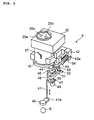
- the operator microscope 6 includes an objective lens barrel portion 10, an inverter portion 20, one pair of right and left eyepieces 30, a front lens 40, and a holding arm 41 that holds the front lens 40.
- the holding arm 41 is connected to the objective lens barrel portion 10 through various members to be described later.
- FIGS. 3A and 3B each show a partial construction of an optical system embedded in the objective lens barrel portion 10, with FIG. 3A being a side view and FIG. 3B being a front view.
- FIG. 3B the illustration of an illumination prism 13 is omitted and there is shown a state where a stereo variator 14 to be described later is arranged on an optical axis.
- An objective lens 11 set so as to confront the eye to be operated E, a zoom lens 12, a not-shown light source (see a light source 63 in FIG. 7), the illumination prism 13, and the stereo (angle) variator 14 are housed in the objective lens barrel portion 10.
- the illumination prism 13 is arranged at a position decentered from an optical axis O of the objective lens 11, and is an optical element for deflecting a light flux emitted from the light source and illuminating the eye to be operated E.
- the zoom lens 12 is composed of one pair of a right zoom lens 12R and a left zoom lens 12L arranged at positions that are symmetrical about the optical axis O of the objective lens 11, and is one pair of right and left optical systems for guiding a reflection light flux (observation light flux) from the illuminated eye to be operated E to the right and left eyepieces, respectively.
- the stereo variator 14 is an optical axis position changing element for changing the relative positions of optical axes OR and OL of the observation light flux to be guided by the respective right and left zoom lenses 12R and 12L, and is moved so as to be inserted/removed onto/from the.optical path of the observation light flux by a solenoid (optical axis position changing element insertion/removal means) to be described later (driven in an arrow direction shown in FIG. 3A).
- the light source 63 and the illumination prism 13 constitute an illumination means of the present invention and are set so as to be capable of changing the angle of the illumination light flux illuminating the eye to be operated E with respect to the optical axes OR and OL.
- the objective lens 11 and the front lens 40 are arranged so that the front-side focal position of the objective lens 11 and the rear-side focal position of the front lens 40 coincide with each other (see a point F in FIG. 3A) .
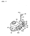
- FIG. 4 shows an internal construction of the inverter portion 20.
- an optical unit 21 for converting an inverted observation image into an erected image is housed in a casing 20A and is set so as to be movable on a slide rail 22 provided in a bottom portion of the casing 20A.
- the optical unit 21 is driven by a drive mechanism (optical unit insertion/removal means) to be described later housed in the inverter portion 20 to move along the slide rail 22.
- connection portion 20a for attachment of the eyepieces 30 is provided on the upper surface of the inverter portion 20, with an opening portion 20b, through which a light flux to be guided to the eyepiece 30 for the left eye passes, and an opening portion 20c, through which a light flux to be guided to the eyepiece 30 for the right eye passes, being established in the connection portion 20a.
- an opening portion 21b, through which the light flux to be guided to the eyepiece 30 for the left eye passes, and an opening portion 21c, through which the light flux to be guided to the eyepiece 30 for the right eye passes, are established in the upper surface of the optical unit 21.
- the position of the optical unit 21 under a state where the opening portion 20b and the opening portion 21b are arranged on a straight line and the opening portion 20c and the opening portion 21c are arranged on a straight line will be hereinafter referred to as the "inverter-on position".
- the position of the optical unit 21 under a state where it is set at a position other than the inverter-on position will be hereinafter referred to as the "inverter-off position". If the optical unit 21 is set at the inverter-on position, an inverted observation image is converted into an erected image. On the other hand, if the optical unit 21 is set at the inverter-off position, an observation image is recognized as it is.
- FIG. 4 shows a state where the optical unit 21 is set at the inverter-on position.
- a construction for holding the front lens 40 and inserting/removing the front lens 40 onto/from the space between the eye to be operated E and the objective lens 11 will be described with reference to FIGS. 2, 5, and 6.
- a holding plate 41a is formed and the front lens 40 is attached to the holding plate 41a.
- a fixing bracket 42 is fixed to the objective lens barrel portion 10 and a supporting rod 43 is attached to the fixing bracket 42 through a rotating shaft 42a serving as an axis.
- a supporting bracket 44 is fixed to the supporting rod 43 using a fixing screw 45.
- a holding frame portion 46 of the supporting bracket 44 is formed in a "U-letter" shape having a lower plate 47 and an upper plate 48, with the lower plate 47 being provided with a fine-movement adjustment knob 49 for finely adjusting the position of the front lens 40 in the upward/downward direction (in the arrow direction shown in FIG. 2).
- a revolving screw 50 is provided between the lower plate 47 and the upper plate 48 and fixes a movable plate 51 to the holding frame portion 46.
- a base end portion of the holding arm 41 is inserted through a not-shown through-hole established in the supporting bracket 44.
- the movable plate 51 is provided with an arm portion 52 and the holding arm 41 engages with this arm portion 52.
- the holding arm 41 is also displaced in the upward/downward direction accordingly. In this manner, the front lens 40 is fine by adjusted in its position.
- the supporting bracket 44 is provided with a swing lever 53 and the holding arm 41 is set so as to be swingable about the rotating shaft 42a using the swing lever 53.
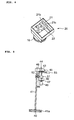
- FIG. 6 shows a state where the holding arm 41 is swung and is set under a standing state. It is possible to set the holding arm 41 under the standing state at a received position by retracing the front lens 40 from the eye to be operated E in the case of observing the anterior portion of the eye to be operated E or using a contact lens, for instance.
- the supporting rod 43 is provided with a coil spring 54 serving as an elastic member for maintaining a used state and a retracted state of the front lens 40.
- a bearing portion 42b of the fixing bracket 42 for supporting the rotating shaft 42a shown in FIG. 6 is provided with a micro-switch as a detecting means (see a micro-switch 65 in FIG. 7) to be described later.
- the micro-switch is turned on when the holding arm 41 is lowered and the front lens 40 is set under the used state, and is turned off when the holding arm 41 is swung and the front lens 40 is set under the retracted state. With this construction, it becomes possible to detect whether the front lens 40 is used or retracted.
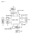
- the operation microscope 1 is entirely controlled by a control circuit 60 (control means) .
- This control circuit 60 is constructed so as to include a non-volatile storage means, such as a ROM, storing a control program and the like and a computation control means, such as a CPU, that generates a control signal in accordance with the control program stored in the storage means, transmits the control signal to each portion relating to control, and recognizes the state of each portion of the apparatus.
- the control circuit 60 is housed in the inverter portion 20 of the operator microscope 6, for instance.
- the micro-switch 61 described above is provided for the drive apparatus 5 for three-dimensionally driving the operator microscope 6 and judges the arrangement of the operator microscope 6 in the upward/downward direction.
- the solenoid 62 described above for driving the stereo variator 14 so as to be inserted/removed onto/from the optical path is connected to the stereo variator 14.
- the light source 63 described above for emitting the illumination light flux for illuminating the eye to be operated E through the illumination prism 13 is provided. This light source 63 is set so as to be capable of changing its turned-on position based on a control signal from the control circuit 60, thereby switching the angle (angle " ⁇ " shown in FIG.
- the solenoid 62 and the light source 63 operate by power from a not-shown power supply apparatus.
- the drive mechanism 64 described above that drives the optical unit 21 along the slide rail 22 and performs switching between the inverter-on position and the inverter-off position is connected to the optical unit 21 of the inverter portion 20.
- the aforementioned micro-switch 65 (detecting means) provided for the bearing portion 42b of the fixing bracket 42 detects the use/retraction of the front lens 40 based on the arrangement state of the holding arm 41.
- the bearing portion 42b is provided with a stopper 66 that prevents the swinging of the holding arm 41 and lifts the prevention.
- the stopper 66 prevents the downward swinging of the holding arm 41 in two steps. That is, at a position (hereinafter referred to as the "swing limit position") midway through the changing of the front lens 40 from the retracted state to the used state, the stopper 66 temporarily limits the swinging, lifts this limitation after a predetermined processing is finished, and allows the holding arm 41 to be swung until coming to the used state.
- the control circuit 60 recognizes the arrangement of the operator microscope 6 in the upward/downward direction based on the judgment by the micro-switch 61. Also, the control circuit 60 recognizes whether the front lens is set under the used state or the retracted state based on the judgment made by the micro-switch 65. Further, the control circuit 60 controls the operation of each of the drive apparatus 5, the solenoid 62, the light source 63, the drive mechanism 64, and the stopper 66.
- the objective lens barrel portion 10 of the operator microscope 6 is provided with a change-over switch 67 constituting a switching means of the present invention.
- the change-over switch 67 is a switch for performing a switching operation of the movement of the operator microscope 6 in the upward/downward direction by the drive apparatus 5. Note that when the front lens 40 is used, the operator microscope 6 is raised and, when the front lens 40 becomes unnecessary and is retracted, the operator microscope 6 is lowered.
- the objective lens 11 and the front lens 40 are attached to the objective lens barrel portion 10, so that when the operator microscope 6 is moved by the movement means 5, the objective lens 11 and the front lens 40 are also moved accordingly.
- this operation microscope 1 is characterized by its construction enabling automatic control and manipulations that should be performed in response to switching between the used state and the retracted state of the front lens 40.
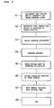
- FIG. 8 An operation of the operation microscope 1 in the case where transition from the observation of the anterior portion of the eye to be operated E to the observation of the retina/vitreous body thereof is performed by switching the front lens 40 from the retracted state to the used state will be described by following a flowchart shown in FIG. 8.
- the operator microscope 6 is arranged on a lower side, the stereo variator 14 is arranged outside the optical path, the light source 63 is turned on at a position at which the illumination light flux is projected so as to form a small angle ⁇ (2°) with respect to the observation optical axis O, and the optical unit 21 is arranged at the inverter-off position.
- the stopper 66 is activated and prevents the downward swinging of the holding arm 41 and the change-over switch 67 is switched to its lower position as shown in FIG. 6.
- the control circuit 60 recognizes that the holding arm 41 is set under the standing state and the front lens 40 is set under the retracted state (S1).
- the control circuit 60 controls the drive apparatus 5 so that the operator microscope 6 is raised (S3).
- the control circuit 60 performs control so that the prevention of the swinging of the holding arm 41 by the stopper 66 is lifted (S4) .
- control circuit 60 controls the drive mechanism 64 so that the optical unit 21 is moved to the inverter-on position (S5) , changes the turned-on position of the light source 63 so that the illumination light flux forms a large angle ⁇ (4°) with respect to the observation optical axis O (S6), controls the solenoid 62 so that the stereo variator 14 is moved and arranged on the optical path (S7), and ends the control processing (S8) .
- the control processing S8 .
- the interlocking movement (S7) of the stereo variator 14 is not necessarily required.
- the downward swinging of the holding arm 41 is prevented by the action of the stopper 66 unless the operator microscope 6 is raised. This is because if the holding arm 41 is swung downwardly under a state where the operator microscope 6 is arranged on the lower side, there is a danger that the front lens 40 may hit the eye to be operated E.
- an alarm sound may be outputted in order to inform the operator of this situation.
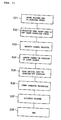
- FIG. 9 An operation of the operation microscope 1 in the case where the front lens 40 set under the used state is retracted in order to perform transition from the observation of the retina/vitreous body to the observation of the anterior portion will be described by following a flowchart shown in FIG. 9.
- the operator microscope 6 is set on the upper side, the stereo variator 14 is arranged on the optical path, the light source 63 is turned on at a position at which the illumination light flux is projected so as to form a large angle (4°) with respect to the observation optical axis O, and the optical unit 21 is arranged at the inverter-on position.
- the change-over switch 67 is switched to the upper position as shown in FIG. 2.
- the reason why the illumination light flux is projected by a large angle with respect to the observation optical axis is to avoid an influence of the reflection light of the illumination light flux by the cornea on the observation light flux.
- the control circuit 60 recognizes that the holding arm 41 is lowered and the front lens 40 is set under the used state (S11).
- the control circuit 60 controls the solenoid 62 so that the stereo variator 14 is retracted from the optical path (S13), changes the turned-on position of the light source 63 so that the illumination light flux forms a small angle (2°) with respect to the observation optical axis O (S14) , and controls the drive mechanism 64 so that the optical unit 21 is moved to the inverter-off position (S15) .
- the control circuit 60 recognizes whether the holding arm 41 is upwardly swung by the operator and the front lens 40 is set under the retracted state based on a signal from the micro-switch 65 (S16) . So long as the front lens 40 is set under the used state, the control circuit 60 maintains its waiting state (S16; N). When the holding arm 41 is swung and is set under the standing state (S16; Y), the control circuit 60 controls the drive apparatus 5 so that the operator microscope 6 is lowered (S17). Finally, the control circuit 60 prevents the downward swinging of the holding arm 41 by activating the stopper 66 (S18). Then, the control processing is finalized (S19).
- step S16 the recognition of whether the holding arm 41 is swung is not necessarily performed in step S16, and this recognition may be performed at any other point in time in the course of the control of the solenoid 62, the light source 63, and the drive mechanism 64. Also, control is performed so that the operator microscope 6 is prevented from being lowered unless the holding arm 41 is swung. This is because if the operator microscope 6 is lowered under a state where the front lens 40 is set under the used state, there is a danger that the front lens 40 may hit the eye to be operated E.
- the holding arm 41 is manually swung by the operator himself/herself.
- a drive mechanism for swinging and driving the holding arm 41 may be provided and the swinging operation may be automatically performed. Note that it is assumed that the automatic swinging is performed at the same timings as in the case of the manual swinging described above.
- each portion of the apparatus is automatically controlled and a setting appropriate for observation is made in response to switching of the change-over switch 67 for performing upward/downward movement of the operator microscope 6.
- a setting appropriate for observation is made in response to switching of the change-over switch 67 for performing upward/downward movement of the operator microscope 6.
- the control circuit 60 controls the drive apparatus 5 so that the operator microscope 6 is raised based on a signal, which shows that the retracted state is cleared, from the micro-switch 65 serving as the detecting means (S22).
- the control circuit 60 lifts the limitation of the swinging of the holding arm 41 by the stopper 66 (S23).
- control circuit 60 controls the drive mechanism 64 so that the optical unit 21 is moved to the inverter-on position (S24), changes the turned-on position of the light source 63 so that the illumination light flux forms a large angle with respect to the observation optical axis O (S25) , controls the solenoid 62 so that the stereo variator 14 is moved and arranged on the optical path (S26), and finalizes the control processing (S27).
- the control circuit 60 recognizes that the front lens 40 is set under the retracted state based on a signal from the micro-switch 65 (S32).
- the control circuit 60 controls the solenoid 62 so that the stereo variator 14 is retracted from the optical path (S33) , changes the turned-on position of the light source 63 so that the illumination light flux forms a small angle with respect to the observation optical axis O (S34), controls the drive mechanism 64 so that the optical unit 21 is moved to the inverter-off position (S35) , controls the drive apparatus 5 so that the operator microscope 6 is lowered (S36), and prevents the swinging of the holding arm 41 by activating the stopper 66 (S37) . Then, the control processing is finalized (S38). Note that here, like in the above cases, it is not necessarily required to perform the control of the solenoid 62, the light source 63, and the drive mechanism 64 in the order described above and it is possible to perform this control in an arbitrary order.
- the micro-switch 65 for recognizing the arrangement of the holding arm 41 serves as the detecting means for switching the setting in accordance with the current state of the front lens 40, that is, use/retraction of the front lens 40.
- the operation microscope according to the present invention may be constructed so as to achieve only one of the first control mode and the second control mode described in detail above.
- the operation microscope according to the present invention may be constructed so that both of the control modes are prepared and either of them is selectively adopted through a manipulation by the operator or the like.
- FIGS. 12A to 12C each show a schematic construction of an operator microscope 106 that is a characteristic portion of an operation microscope 101 of the second embodiment.
- FIG. 12A is an external side view of the operator microscope 106 and
- FIG. 12B is an external front view thereof.
- FIG. 12C is a see-through side view showing a received mode of a front lens.
- the operation microscope 101 has the same construction as the operation microscope 1 of the first embodiment.
- the operator microscope 106 is capable of being moved upwardly/downwardly by a drive apparatus that is the same as the drive apparatus 5 in the first embodiment.
- the operator microscope 106 of this embodiment includes an objective lens barrel portion 110, an inverter portion 120, eyepieces 130, a front lens 140, and a holding arm 141 provided with a holding plate 141a.
- the objective lens barrel portion 110 is capable of being finely moved upwardly/downwardly with respect to a main body portion 106a in a range of ⁇ 10 mm through a manipulation of a not-shown foot switch, for instance. Also, it is assumed that the moving speed during the upward/downward fine movement is set at around 1 mm per second, for instance.
- the objective lens barrel portion 110 is provided with an objective lens 111 and a zoom lens 112. It is possible to change the position of the zoom lens 112 using a drive apparatus (drive apparatus 178 in FIG. 13; a zoom magnification changing means) to be described later, thereby changing the zoom magnification of an observation image.
- the initial position of the zoom lens 112 is predetermined.
- the initial zoom magnification set in this manner is stored in a storage means of a control circuit 160 (see FIG. 13) to be described later.
- a raising switch 167a to be pressed down for upwardly moving the operator microscope 106 and a lowering switch 167b to be pressed down for downwardly moving the operator microscope 106.
- the raising switch 167a and the lowering switch 167b constitute the switching means of the present invention.
- the operator microscope 106 is moved by a drive apparatus 105 shown in FIG. 13 to be described later in response to the pressing-down of those switches.
- the raising switch 167a and the lowering switch 167b are each covered with a detachably attached sterilized cap, thereby preventing a patient from being infected during an operation.
- the holding arm 141 and the holding plate 141a are rotatably connected to each other through a rotation shaft 141b. Also, the holding plate 141a is provided with an inclined portion 141c. Further, the holding arm 141 is provided with a front lens manipulation knob 142 for swinging the holding arm 141.
- the operator microscope 106 further includes an elevator arm 171 provided with a fringe portion 171a in its upper portion, a connection portion 171b connected to the lower portion of the elevator arm 171, a raising-limit member 172 connected to the connection portion 171b, a coupling knob 173 inserted through the connection portion 171b, and a receiving portion 174 that is detachably attached to the raising degree regulation member 172 and is used for receiving the front lens 140 and the holding arm 141.
- the holding arm 141 is rotated to the receiving portion 174 through a rotating shaft 174a.
- a coil spring 154 is attached to the holding arm 141.
- the reason why the receiving portion 174 is detachably attached to the raising-limit member 172 is that it is required to detach the front lens 140 and the holding arm 141 at the time of sterilization after an operation or the like. Also, even under a state where the front lens 140 and the like are detached, it is possible to use the operation microscope of the present invention as an ordinary operation microscope. In the following description, the construction elements described in this paragraph will be collectively referred to as the "front lens supporting portion" in some cases.
- the operator microscope 106 is provided with a drive portion 175 for upwardly/downwardly driving an elevator arm supporting member 176 for supporting the elevator arm 171.
- the elevator arm 171 is inserted through the elevator arm supporting member 176. Also, the elevator arm 171 is prevented from dropping from the elevator arm supporting member 176 by the fringe portion 171a.
- the initial position of the front lens 140 is predetermined as a reference position of the upward/downward movement.
- the initial position is set so that a sufficient distance is maintained between the front lens 140 and the eye to be operated E with consideration given to the safety of a patient.
- the initial position of the front lens set in this manner is stored in the storage means of the control circuit 160 (see FIG. 13) to be described later.
- the drive portion 175 constitutes a front lens moving means of the present invention. With this construction, it becomes possible to upwardly/downwardly move only the front lens 140 independently of the upward/downward fine movement of the objective lens barrel portion 110.
- the displacement degree of the front lens 140 during the upward/downward movement is set at around ⁇ 10 mm with respect to the initial position described above, for instance.
- the moving speed is set at around 1 mm per second, for instance.
- a raising limit member 177 for regulating the upward moving range of the front lens supporting portion is attached in addition to the raising limit member 172.
- this raising limit member 177 there is established a coupling hole 177a for coupling the front lens supporting portion to the main body portion 106a through a manipulation of the coupling knob 173.
- the coupling of the front lens supporting portion to the main body portion 106a is performed by raising the front lens supporting portion using the drive portion 175 (setting is made in advance so that a convex portion 173a of the coupling knob 173 is aligned with the coupling hole 177 at this point in time) and then fitting the convex portion 173a into the coupling hole 177a through a rotary manipulation of the coupling knob 173 in a predetermined direction. That is, in the received state of the front lens 140 shown in FIG. 12C, while raising the front lens supporting portion and complying the raising limit member 177 of the main body and the raising limit member 172 provided on the upper portion of the front lens supporting portion, the convex portion 173 is made to be coupled in the coupling hole 177a.
- FIGS. 12A and 12B each show a state where the front lens 140 of the operator microscope 106 is inserted into the space between an eye to be operated E and the objective lens 111, that is, a used state of the front lens 140.
- the operator grabs the front lens manipulation knob 142 and upwardly swings the holding arm 141 about the rotating shaft 174a. Consequently, the front lens 140 and the holding arm 141 are received in the receiving portion 174.
- the holding arm 141 is downwardly swung in a like manner.
- FIG. 12C shows a state where the front lens 140 is received in the receiving portion 174 (received position).
- the front lens 140 and the holding arm 141 are upwardly swung about the rotating shaft 174a and are received in the receiving portion 174.
- the holding plate 141a is received under a state where it is rotatively moved about the rotating shaft 141b and is folded.
- a contact member 174b is attached to an end portion of the receiving portion 174.
- a micro-switch 165 as a detecting means is provided which is turned on when the holding plate 141a is received and is turned off when the received state is cleared.
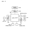
- FIG. 13 is a block diagram schematically showing a construction for controlling the operation of each portion of the operation microscope 101.
- the operation microscope 101 is provided with the control circuit 160 for performing control of each portion of the apparatus.
- Connected to the control circuit 160 are the drive portion 175 provided on a side surface of the main body portion 106a and the micro-switch 165 (detection means) provided for the receiving portion 174.
- the drive apparatus 178 for changing the zoom magnification by driving the zoom lens 112 is connected to the control circuit 160.
- the drive apparatus 105 for upwardly/downwardly moving the operator microscope 106 and the raising switch 167a and the lowering switch 167b to be pressed down in order to have the drive apparatus 105 operate are connected to the control circuit 160.
- the operator microscope 101 achieves the action shown in the flowcharts in FIGS. 14 and 15.
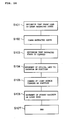
- a control mode at the time when the front lens 140 transits from the retracted state to the used state will be described with reference to FIG. 14.
- the control circuit 160 recognizes that the front lens 140 is set under the retracted state by checking that the micro-switch 165 is turned on (S101).
- the micro-switch 165 is turned off and the control circuit 160 recognizes that the retracted state is cleared (S103).
- the control circuit 160 transmits a control signal to the drive portion 175, which then sets the optical unit to move into the inverter on position (S104).
- control circuit 160 changes the turning on position of the light source in order to make the illumination light flux big angle to the observation light axis O (S105) . Then, the stereo variator is moved on the light channel (5106), and the control treatment is finalized. Note that it is not necessarily required to perform those process in this order, and it is also possible to perform those operations in an inverse order or at the same time.
- the control circuit 160 recognizes that the front lens 140 is set under the insertion state by checking that the micro-switch 165 is turned off (S111).
- the micro-switch 165 detects this and the control circuit 160 recognizes that the front lens 140 is set under the removal state (S113).
- the control circuit 160 transmits a control.
- the drive portion 175 which then calculates the front lens 140 at the initial position. That is, when the front lens is received, the distance between the eyepiece and the next use time' s position of the front lens is determined to calculate as the initial position. And then, the drive portion 175 is driven to move the elevator arm member 176 upward/downward and the initial position is set (S114). Then, while raising the auxiliary lens supporting portion manually, as described above, keep it contacted to the raising limit member 177. Then, the control processing is finalized (S115).
- the initial position of the front lens 140 is automatically calculated. Accordingly, by presetting the initial position and the initial magnification so as to be suited for the contents of an operation or the like, there is eliminated the necessity to manually perform those manipulations each time switching between observation methods is performed during an operation. As a result, it becomes possible to improve manipulability.
- control may be performed so that when the micro-switch 165 is turned off (when it is recognized that the front lens 140 is set under the used state), the downward movement of the operator microscope 106 is not performed even if the lowering switch 167b is pressed down or control may be performed so that when it is recognized that the received state of the front lens 140 is cleared and the micro-switch 165 is turned off during the downward movement of the operator microscope 106, an alarm sound is outputted.
- the raising switch 167a is pressed down and the operator microscope 106 is upwardly moved only by a predetermined amount (57 mm, for instance).
- the holding arm 141 is swung and the front lens 140 received in the receiving portion 174 is set under the used state.
- the irradiation angle of the illumination light flux is set at a large angle (4°, for instance) , the stereo variator and the optical unit are arranged on the observation optical axis, and the lens 140 is returned to the initial position.
- those interlocked operations may be performed in response to the pressing-down of the raising switch 167a.
- the stereo variator is not arranged.
- the coupling state is cleared by rotating the coupling knob 173 and the front lens 140 is lowered to a lower limit position (lowered from the initial position by 10 mm, for instance) by the drive portion 175.
- the front lens 140 When a flare occurs in an observation image of the eye to be operated, the front lens 140 is adjusted to an appropriate position through upward/downward movement by the drive portion 175. Note that from the viewpoint of elimination of the flare, the adjustment of alignment in the horizontal direction performed at the time of start of an operation is also an important factor.
- the objective lens barrel portion 110 is upwardly/downwardly fine by moved with respect to the main body portion 106 and is focused on an observation position. As described above, with the operation microscope 101, it is possible to upwardly/downwardly drive the front lens 140 and the objective lens barrel portion 110 independently of each other, thereby allowing the front lens 140 and the objective lens barrel portion to be accurately set, respectively. Note that, when the flare still remains, it is sufficient that the alignment is performed by inserting an illumination filed diaphragm.
- an eyefundus periphery observation prism is arranged on an upper surface of the front lens 140, alignment in the horizontal direction is performed using the drive apparatus 105, and adjustment is performed so that the illumination light flux strikes the eye to be operated E. Further, if necessary, the flare resolving and the focusing are performed in the manner described above.
- an assistant extracts an anterior portion observation lens from a port and inserts it above the front lens 140 by holding the anterior portion observation lens in his/her hand.
- the insertion position of the anterior portion observation lens is determined by the assistant himself/herself through observation.
- the holding arm 141 When the observation of the periphery of the eyefundus is finished, the holding arm 141 is swung and the front lens 140 is received in the receiving portion 174.
- the irradiation angle of the illumination light flux is set at a small angle (2°, for instance), the stereo variator and the optical unit are retracted from the observation optical axis, and the initial position of the lens 140 is calculated.
- the lowering switch 167b is pressed down, the operator microscope 106 is moved downwardly, and the front lens and the like are coupled to the main body portion 106a through the coupling knob 173. Note that the interlocked operations performed at the time when the eyefundus periphery observation is finished may be performed in response to the pressing down of the lowering switch 167b.
- the micro-switch 165 is provided in the receiving portion 174.
- this micro-switch may be arranged at another position so long as it is possible to detect the current state of the front lens 140, that is, whether the front lens 140 is set under the used state or under the unused and received state.
- the micro-switch 165 may be provided at a contact portion between the raising-limit member 172 and the raising-limit member 177 used at the time when the holding arm 141 is raised by the drive portion 175 (at the upper surface portion of the raising-limit member 172 or the lower surface portion of the raising-limit member 177).
- the micro-switch is turned on when those members contact each other and is turned off when the members are spaced apart from each other. Then, based on the on/off-state of the micro-switch, the current state of the front lens 140 is judged and each portion of the apparatus is controlled in an interlocked manner. In this case, when the raising regulation members 172 and 177 contact each other, the front lens 140 is set at the received position. With the construction described above where the current state of the front lens 140 is detected using the micro-switch and the downward movement is prevented when the front lens 140 is used, it becomes possible to avoid a situation where the front lens 140 hits the eye to be operated E, which enhances safety.
- the detecting means for detecting the current state of the front lens 140 is not limited to the micro-switch and it is of course possible to use any other detection member so long as it has the same action.
- Each control mode described in detail above is an example of the control by the operation microscope according to the present invention. For instance, it is of course possible to perform the control in a mode where any steps of the control processing described above are omitted. Also, an operation microscope having various functions is currently available and it is possible to control each member for achieving the various functions in accordance with whether a front lens is used or retracted.
- a manipulation portion for performing selection from among various modes for observing an eye to be operated such as an anterior portion observation mode, a contact lens use mode, and a retina/vitreous body observation mode, may be provided and a member to be used in the selected mode may be prepared in response to the changing of arrangement of the front lens at the time of transition to the selected mode.
Applications Claiming Priority (2)
| Application Number | Priority Date | Filing Date | Title |
|---|---|---|---|
| JP2003037646 | 2003-02-17 | ||
| JP2003037646 | 2003-02-17 |
Publications (3)
| Publication Number | Publication Date |
|---|---|
| EP1447698A2 true EP1447698A2 (fr) | 2004-08-18 |
| EP1447698A3 EP1447698A3 (fr) | 2004-11-17 |
| EP1447698B1 EP1447698B1 (fr) | 2007-04-11 |
Family
ID=32677650
Family Applications (1)
| Application Number | Title | Priority Date | Filing Date |
|---|---|---|---|
| EP04003411A Expired - Lifetime EP1447698B1 (fr) | 2003-02-17 | 2004-02-16 | Microscope d'opération ophthalmique |
Country Status (6)
| Country | Link |
|---|---|
| US (1) | US7232222B2 (fr) |
| EP (1) | EP1447698B1 (fr) |
| KR (1) | KR101092108B1 (fr) |
| CN (1) | CN100347583C (fr) |
| AT (1) | ATE359533T1 (fr) |
| DE (1) | DE602004005764T2 (fr) |
Cited By (2)
| Publication number | Priority date | Publication date | Assignee | Title |
|---|---|---|---|---|
| EP2096481A3 (fr) * | 2008-02-28 | 2009-10-28 | Carl Zeiss Surgical GmbH | Dispositif de montage pour un dispositif d'observation optique |
| EP2248460A1 (fr) * | 2008-03-03 | 2010-11-10 | Kabushiki Kaisha TOPCON | Microscope stéréoscopique |
Families Citing this family (23)
| Publication number | Priority date | Publication date | Assignee | Title |
|---|---|---|---|---|
| DE10336475B9 (de) | 2003-08-08 | 2006-09-07 | Carl Zeiss | Mikroskopiesystem |
| JP2006325936A (ja) * | 2005-05-26 | 2006-12-07 | Topcon Corp | 眼科装置 |
| JP4444194B2 (ja) * | 2005-09-30 | 2010-03-31 | 株式会社トプコン | 眼科用顕微鏡 |
| JP5090807B2 (ja) * | 2007-07-10 | 2012-12-05 | 株式会社トプコン | 手術用顕微鏡装置 |
| WO2010060622A2 (fr) * | 2008-11-26 | 2010-06-03 | Carl Zeiss Surgical Gmbh | Système d'imagerie |
| DE102009018114A1 (de) * | 2009-04-20 | 2011-01-05 | Dieter Mann Gmbh | Weitwinkelbeobachtung am Operationsmikroskop |
| USD649992S1 (en) | 2009-12-22 | 2011-12-06 | Carl Zeiss Meditec Ag | Stand for microscope assembly |
| KR101476820B1 (ko) | 2014-04-07 | 2014-12-29 | 주식회사 썸텍 | 3d 비디오 현미경 장치 |
| USD836692S1 (en) | 2014-06-30 | 2018-12-25 | Carl Zeiss Meditec Ag | Surgical microscope |
| USD836693S1 (en) * | 2014-06-30 | 2018-12-25 | Carl Zeiss Meditec Ag | Stand for a surgical microscope |
| JP6997207B2 (ja) | 2017-03-22 | 2022-01-17 | アルコン インコーポレイティド | 再設定可能な外科用顕微鏡 |
| US11045089B2 (en) | 2017-05-19 | 2021-06-29 | Alcon Inc. | Automatic lens to cornea standoff control for non-contact visualization |
| DE102017214790A1 (de) * | 2017-08-24 | 2019-02-28 | Carl Zeiss Meditec Ag | Vorrichtung zur motorischen Verstellung der Vergrößerungsstufen eines Vergrößerungswechslers |
| JP1623665S (fr) * | 2018-02-13 | 2019-02-04 | ||
| CN110068919A (zh) * | 2019-05-29 | 2019-07-30 | 苏州四海通仪器有限公司 | 一种便拆式手术显微镜 |
| CN110068920A (zh) * | 2019-05-29 | 2019-07-30 | 苏州四海通仪器有限公司 | 一种用于显微镜的非接触广角倒像装置及显微镜系统 |
| KR102242014B1 (ko) | 2019-06-10 | 2021-04-19 | 가톨릭대학교 산학협력단 | 조명부가 구비된 안과수술장치 |
| USD1010315S1 (en) | 2019-09-06 | 2024-01-09 | Carl Zeiss Meditec Ag | Surgical microscope |
| USD934327S1 (en) | 2020-03-11 | 2021-10-26 | Carl Zeiss Meditec Ag | Surgical microscope |
| USD934937S1 (en) | 2020-03-11 | 2021-11-02 | Carl Zeiss Meditec Ag | Surgical microscope |
| USD1026227S1 (en) * | 2021-01-29 | 2024-05-07 | Align Technology, Inc. | Intraoral scanning system cart |
| US20240041555A1 (en) * | 2022-08-03 | 2024-02-08 | Alcon Inc. | Ophthalmic viewing devices |
| KR20240028675A (ko) | 2022-08-25 | 2024-03-05 | 최성백 | 의료 수술용 디지털 현미경 |
Citations (4)
| Publication number | Priority date | Publication date | Assignee | Title |
|---|---|---|---|---|
| US4838671A (en) * | 1986-03-14 | 1989-06-13 | Haag-Streit Ag | Stereo microscope and stereo changer |
| US5760952A (en) * | 1996-01-25 | 1998-06-02 | J.D. Moller Optische Werke Gmbh | Illuminating device for a surgical microscope |
| US20020044256A1 (en) * | 2000-10-18 | 2002-04-18 | Rainer Kirchhuebel | Microscope for noncontact wide-angle viewing |
| US20020191280A1 (en) * | 2001-06-13 | 2002-12-19 | Kabushiki Kaisha Topcon | Microscope for operation |
Family Cites Families (11)
| Publication number | Priority date | Publication date | Assignee | Title |
|---|---|---|---|---|
| US4807989A (en) * | 1986-01-14 | 1989-02-28 | Olympus Optical Co., Ltd. | Surgical microscope system |
| US4932774A (en) * | 1987-02-24 | 1990-06-12 | Tokyo Kogaku Kikai Kabushiki Kaisha | Illuminating system of ophthalmological instrument |
| US4863252A (en) * | 1988-02-11 | 1989-09-05 | Tracor Northern, Inc. | Objective lens positioning system for confocal tandem scanning reflected light microscope |
| DE69528024T2 (de) * | 1994-08-18 | 2003-10-09 | Zeiss Carl | Mit optischer Kohärenz-Tomographie gesteuerter chirurgischer Apparat |
| GB9813041D0 (en) * | 1998-06-16 | 1998-08-12 | Scient Generics Ltd | Eye tracking technique |
| GB9823977D0 (en) * | 1998-11-02 | 1998-12-30 | Scient Generics Ltd | Eye tracking method and apparatus |
| JP2000312685A (ja) | 1999-04-30 | 2000-11-14 | Olympus Optical Co Ltd | 手術用顕微鏡装置 |
| JP2001108906A (ja) | 1999-10-01 | 2001-04-20 | Topcon Corp | 手術用顕微鏡 |
| JP4554027B2 (ja) | 2000-03-31 | 2010-09-29 | 株式会社トプコン | 眼科装置 |
| JP2002350735A (ja) * | 2001-05-29 | 2002-12-04 | Topcon Corp | 手術用顕微鏡 |
| JP4439815B2 (ja) * | 2002-08-22 | 2010-03-24 | 株式会社トプコン | 手術用顕微鏡 |
-
2004
- 2004-02-16 KR KR1020040009979A patent/KR101092108B1/ko active IP Right Grant
- 2004-02-16 DE DE602004005764T patent/DE602004005764T2/de not_active Expired - Lifetime
- 2004-02-16 AT AT04003411T patent/ATE359533T1/de not_active IP Right Cessation
- 2004-02-16 EP EP04003411A patent/EP1447698B1/fr not_active Expired - Lifetime
- 2004-02-17 US US10/778,336 patent/US7232222B2/en active Active
- 2004-02-17 CN CNB2004100052089A patent/CN100347583C/zh not_active Expired - Fee Related
Patent Citations (4)
| Publication number | Priority date | Publication date | Assignee | Title |
|---|---|---|---|---|
| US4838671A (en) * | 1986-03-14 | 1989-06-13 | Haag-Streit Ag | Stereo microscope and stereo changer |
| US5760952A (en) * | 1996-01-25 | 1998-06-02 | J.D. Moller Optische Werke Gmbh | Illuminating device for a surgical microscope |
| US20020044256A1 (en) * | 2000-10-18 | 2002-04-18 | Rainer Kirchhuebel | Microscope for noncontact wide-angle viewing |
| US20020191280A1 (en) * | 2001-06-13 | 2002-12-19 | Kabushiki Kaisha Topcon | Microscope for operation |
Cited By (6)
| Publication number | Priority date | Publication date | Assignee | Title |
|---|---|---|---|---|
| EP2096481A3 (fr) * | 2008-02-28 | 2009-10-28 | Carl Zeiss Surgical GmbH | Dispositif de montage pour un dispositif d'observation optique |
| EP2194411A1 (fr) * | 2008-02-28 | 2010-06-09 | Carl Zeiss Surgical GmbH | Dispositif de montage pour un dispositif d'observation optique |
| EP2194410A1 (fr) * | 2008-02-28 | 2010-06-09 | Carl Zeiss Surgical GmbH | Dispositif de montage pour un dispositif d'observation optique |
| US8437076B2 (en) | 2008-02-28 | 2013-05-07 | Carl Zeiss Meditec Ag | Front-lens attachment for an optical observation device |
| EP2248460A1 (fr) * | 2008-03-03 | 2010-11-10 | Kabushiki Kaisha TOPCON | Microscope stéréoscopique |
| EP2248460A4 (fr) * | 2008-03-03 | 2013-03-27 | Topcon Corp | Microscope stéréoscopique |
Also Published As
| Publication number | Publication date |
|---|---|
| US7232222B2 (en) | 2007-06-19 |
| US20040183999A1 (en) | 2004-09-23 |
| EP1447698A3 (fr) | 2004-11-17 |
| EP1447698B1 (fr) | 2007-04-11 |
| DE602004005764D1 (de) | 2007-05-24 |
| CN100347583C (zh) | 2007-11-07 |
| CN1523393A (zh) | 2004-08-25 |
| KR101092108B1 (ko) | 2011-12-12 |
| KR20040074933A (ko) | 2004-08-26 |
| DE602004005764T2 (de) | 2008-01-10 |
| ATE359533T1 (de) | 2007-05-15 |
Similar Documents
| Publication | Publication Date | Title |
|---|---|---|
| EP1447698B1 (fr) | Microscope d'opération ophthalmique | |
| US8205988B2 (en) | Stereomicroscope | |
| US6943942B2 (en) | Microscope for operation | |
| US9364146B2 (en) | Slit lamp microscope | |
| US7393103B2 (en) | Operation microscope apparatus | |
| JP5090807B2 (ja) | 手術用顕微鏡装置 | |
| JP4417036B2 (ja) | 眼科用手術顕微鏡 | |
| US10456035B2 (en) | Ophthalmic surgical microscope | |
| JP2009297073A (ja) | 手術用顕微鏡 | |
| JP5491142B2 (ja) | 眼科手術用顕微鏡 | |
| EP2063305A2 (fr) | Microscope chirurgical | |
| JP4717360B2 (ja) | 手術用顕微鏡 | |
| JP2009072513A (ja) | 眼科装置 | |
| US6705728B2 (en) | Ophthalmologic apparatus | |
| JP2001029316A (ja) | 眼屈折力測定装置 | |
| JPH11225958A (ja) | 眼科装置用顎台装置および眼科装置 | |
| JP2009095518A (ja) | 細隙灯顕微鏡 | |
| JP2002350735A (ja) | 手術用顕微鏡 | |
| JP2009066258A (ja) | 眼科装置 | |
| JP6444659B2 (ja) | 眼科装置 | |
| JP4498547B2 (ja) | 眼科装置 | |
| JP3656770B2 (ja) | 眼科装置 | |
| JPH09276228A (ja) | 顕微鏡 |
Legal Events
| Date | Code | Title | Description |
|---|---|---|---|
| PUAI | Public reference made under article 153(3) epc to a published international application that has entered the european phase |
Free format text: ORIGINAL CODE: 0009012 |
|
| AK | Designated contracting states |
Kind code of ref document: A2 Designated state(s): AT BE BG CH CY CZ DE DK EE ES FI FR GB GR HU IE IT LI LU MC NL PT RO SE SI SK TR |
|
| AX | Request for extension of the european patent |
Extension state: AL LT LV MK |
|
| PUAL | Search report despatched |
Free format text: ORIGINAL CODE: 0009013 |
|
| AK | Designated contracting states |
Kind code of ref document: A3 Designated state(s): AT BE BG CH CY CZ DE DK EE ES FI FR GB GR HU IE IT LI LU MC NL PT RO SE SI SK TR |
|
| AX | Request for extension of the european patent |
Extension state: AL LT LV MK |
|
| REG | Reference to a national code |
Ref country code: HK Ref legal event code: DE Ref document number: 1067710 Country of ref document: HK |
|
| 17P | Request for examination filed |
Effective date: 20050503 |
|
| AKX | Designation fees paid |
Designated state(s): AT BE BG CH CY CZ DE DK EE ES FI FR GB GR HU IE IT LI LU MC NL PT RO SE SI SK TR |
|
| GRAP | Despatch of communication of intention to grant a patent |
Free format text: ORIGINAL CODE: EPIDOSNIGR1 |
|
| GRAS | Grant fee paid |
Free format text: ORIGINAL CODE: EPIDOSNIGR3 |
|
| GRAA | (expected) grant |
Free format text: ORIGINAL CODE: 0009210 |
|
| AK | Designated contracting states |
Kind code of ref document: B1 Designated state(s): AT BE BG CH CY CZ DE DK EE ES FI FR GB GR HU IE IT LI LU MC NL PT RO SE SI SK TR |
|
| PG25 | Lapsed in a contracting state [announced via postgrant information from national office to epo] |
Ref country code: SI Free format text: LAPSE BECAUSE OF FAILURE TO SUBMIT A TRANSLATION OF THE DESCRIPTION OR TO PAY THE FEE WITHIN THE PRESCRIBED TIME-LIMIT Effective date: 20070411 Ref country code: FI Free format text: LAPSE BECAUSE OF FAILURE TO SUBMIT A TRANSLATION OF THE DESCRIPTION OR TO PAY THE FEE WITHIN THE PRESCRIBED TIME-LIMIT Effective date: 20070411 |
|
| REG | Reference to a national code |
Ref country code: GB Ref legal event code: FG4D |
|
| REG | Reference to a national code |
Ref country code: CH Ref legal event code: EP |
|
| REG | Reference to a national code |
Ref country code: IE Ref legal event code: FG4D |
|
| REF | Corresponds to: |
Ref document number: 602004005764 Country of ref document: DE Date of ref document: 20070524 Kind code of ref document: P |
|
| PG25 | Lapsed in a contracting state [announced via postgrant information from national office to epo] |
Ref country code: SE Free format text: LAPSE BECAUSE OF FAILURE TO SUBMIT A TRANSLATION OF THE DESCRIPTION OR TO PAY THE FEE WITHIN THE PRESCRIBED TIME-LIMIT Effective date: 20070711 |
|
| PG25 | Lapsed in a contracting state [announced via postgrant information from national office to epo] |
Ref country code: ES Free format text: LAPSE BECAUSE OF FAILURE TO SUBMIT A TRANSLATION OF THE DESCRIPTION OR TO PAY THE FEE WITHIN THE PRESCRIBED TIME-LIMIT Effective date: 20070722 |
|
| REG | Reference to a national code |
Ref country code: CH Ref legal event code: NV Representative=s name: VOSSIUS & PARTNER |
|
| PG25 | Lapsed in a contracting state [announced via postgrant information from national office to epo] |
Ref country code: PT Free format text: LAPSE BECAUSE OF FAILURE TO SUBMIT A TRANSLATION OF THE DESCRIPTION OR TO PAY THE FEE WITHIN THE PRESCRIBED TIME-LIMIT Effective date: 20070911 |
|
| NLV1 | Nl: lapsed or annulled due to failure to fulfill the requirements of art. 29p and 29m of the patents act | ||
| PG25 | Lapsed in a contracting state [announced via postgrant information from national office to epo] |
Ref country code: AT Free format text: LAPSE BECAUSE OF FAILURE TO SUBMIT A TRANSLATION OF THE DESCRIPTION OR TO PAY THE FEE WITHIN THE PRESCRIBED TIME-LIMIT Effective date: 20070411 |
|
| EN | Fr: translation not filed | ||
| PG25 | Lapsed in a contracting state [announced via postgrant information from national office to epo] |
Ref country code: BE Free format text: LAPSE BECAUSE OF FAILURE TO SUBMIT A TRANSLATION OF THE DESCRIPTION OR TO PAY THE FEE WITHIN THE PRESCRIBED TIME-LIMIT Effective date: 20070411 |
|
| PG25 | Lapsed in a contracting state [announced via postgrant information from national office to epo] |
Ref country code: CZ Free format text: LAPSE BECAUSE OF FAILURE TO SUBMIT A TRANSLATION OF THE DESCRIPTION OR TO PAY THE FEE WITHIN THE PRESCRIBED TIME-LIMIT Effective date: 20070411 Ref country code: BG Free format text: LAPSE BECAUSE OF FAILURE TO SUBMIT A TRANSLATION OF THE DESCRIPTION OR TO PAY THE FEE WITHIN THE PRESCRIBED TIME-LIMIT Effective date: 20070711 Ref country code: DK Free format text: LAPSE BECAUSE OF FAILURE TO SUBMIT A TRANSLATION OF THE DESCRIPTION OR TO PAY THE FEE WITHIN THE PRESCRIBED TIME-LIMIT Effective date: 20070411 Ref country code: NL Free format text: LAPSE BECAUSE OF FAILURE TO SUBMIT A TRANSLATION OF THE DESCRIPTION OR TO PAY THE FEE WITHIN THE PRESCRIBED TIME-LIMIT Effective date: 20070411 |
|
| REG | Reference to a national code |
Ref country code: CH Ref legal event code: PCAR Free format text: VOSSIUS & PARTNER;NADELBERG 3;4051 BASEL (CH) |
|
| PLBE | No opposition filed within time limit |
Free format text: ORIGINAL CODE: 0009261 |
|
| STAA | Information on the status of an ep patent application or granted ep patent |
Free format text: STATUS: NO OPPOSITION FILED WITHIN TIME LIMIT |
|
| PG25 | Lapsed in a contracting state [announced via postgrant information from national office to epo] |
Ref country code: SK Free format text: LAPSE BECAUSE OF FAILURE TO SUBMIT A TRANSLATION OF THE DESCRIPTION OR TO PAY THE FEE WITHIN THE PRESCRIBED TIME-LIMIT Effective date: 20070411 |
|
| 26N | No opposition filed |
Effective date: 20080114 |
|
| PG25 | Lapsed in a contracting state [announced via postgrant information from national office to epo] |
Ref country code: GR Free format text: LAPSE BECAUSE OF FAILURE TO SUBMIT A TRANSLATION OF THE DESCRIPTION OR TO PAY THE FEE WITHIN THE PRESCRIBED TIME-LIMIT Effective date: 20070712 Ref country code: FR Free format text: LAPSE BECAUSE OF FAILURE TO SUBMIT A TRANSLATION OF THE DESCRIPTION OR TO PAY THE FEE WITHIN THE PRESCRIBED TIME-LIMIT Effective date: 20071207 Ref country code: IT Free format text: LAPSE BECAUSE OF FAILURE TO SUBMIT A TRANSLATION OF THE DESCRIPTION OR TO PAY THE FEE WITHIN THE PRESCRIBED TIME-LIMIT Effective date: 20070411 |
|
| PG25 | Lapsed in a contracting state [announced via postgrant information from national office to epo] |
Ref country code: RO Free format text: LAPSE BECAUSE OF FAILURE TO SUBMIT A TRANSLATION OF THE DESCRIPTION OR TO PAY THE FEE WITHIN THE PRESCRIBED TIME-LIMIT Effective date: 20070411 |
|
| GBPC | Gb: european patent ceased through non-payment of renewal fee |
Effective date: 20080216 |
|
| PG25 | Lapsed in a contracting state [announced via postgrant information from national office to epo] |
Ref country code: MC Free format text: LAPSE BECAUSE OF NON-PAYMENT OF DUE FEES Effective date: 20080228 |
|
| PG25 | Lapsed in a contracting state [announced via postgrant information from national office to epo] |
Ref country code: FR Free format text: LAPSE BECAUSE OF FAILURE TO SUBMIT A TRANSLATION OF THE DESCRIPTION OR TO PAY THE FEE WITHIN THE PRESCRIBED TIME-LIMIT Effective date: 20070411 |
|
| PG25 | Lapsed in a contracting state [announced via postgrant information from national office to epo] |
Ref country code: IE Free format text: LAPSE BECAUSE OF NON-PAYMENT OF DUE FEES Effective date: 20080218 Ref country code: EE Free format text: LAPSE BECAUSE OF FAILURE TO SUBMIT A TRANSLATION OF THE DESCRIPTION OR TO PAY THE FEE WITHIN THE PRESCRIBED TIME-LIMIT Effective date: 20070411 |
|
| PG25 | Lapsed in a contracting state [announced via postgrant information from national office to epo] |
Ref country code: GB Free format text: LAPSE BECAUSE OF NON-PAYMENT OF DUE FEES Effective date: 20080216 |
|
| PG25 | Lapsed in a contracting state [announced via postgrant information from national office to epo] |
Ref country code: CY Free format text: LAPSE BECAUSE OF FAILURE TO SUBMIT A TRANSLATION OF THE DESCRIPTION OR TO PAY THE FEE WITHIN THE PRESCRIBED TIME-LIMIT Effective date: 20070411 |
|
| PG25 | Lapsed in a contracting state [announced via postgrant information from national office to epo] |
Ref country code: HU Free format text: LAPSE BECAUSE OF FAILURE TO SUBMIT A TRANSLATION OF THE DESCRIPTION OR TO PAY THE FEE WITHIN THE PRESCRIBED TIME-LIMIT Effective date: 20071012 Ref country code: LU Free format text: LAPSE BECAUSE OF NON-PAYMENT OF DUE FEES Effective date: 20080216 |
|
| PG25 | Lapsed in a contracting state [announced via postgrant information from national office to epo] |
Ref country code: TR Free format text: LAPSE BECAUSE OF FAILURE TO SUBMIT A TRANSLATION OF THE DESCRIPTION OR TO PAY THE FEE WITHIN THE PRESCRIBED TIME-LIMIT Effective date: 20070411 |
|
| REG | Reference to a national code |
Ref country code: HK Ref legal event code: WD Ref document number: 1067710 Country of ref document: HK |
|
| REG | Reference to a national code |
Ref country code: CH Ref legal event code: PFA Owner name: KABUSHIKI KAISHA TOPCON, JP Free format text: FORMER OWNER: KABUSHIKI KAISHA TOPCON, JP |
|
| REG | Reference to a national code |
Ref country code: DE Ref legal event code: R084 Ref document number: 602004005764 Country of ref document: DE |
|
| PGFP | Annual fee paid to national office [announced via postgrant information from national office to epo] |
Ref country code: CH Payment date: 20230307 Year of fee payment: 20 |
|
| PGFP | Annual fee paid to national office [announced via postgrant information from national office to epo] |
Ref country code: DE Payment date: 20221229 Year of fee payment: 20 |
|
| REG | Reference to a national code |
Ref country code: DE Ref legal event code: R071 Ref document number: 602004005764 Country of ref document: DE |
|
| REG | Reference to a national code |
Ref country code: CH Ref legal event code: PL |