EP1447669A2 - Chemical analysis apparatus - Google Patents
Chemical analysis apparatus Download PDFInfo
- Publication number
- EP1447669A2 EP1447669A2 EP04002600A EP04002600A EP1447669A2 EP 1447669 A2 EP1447669 A2 EP 1447669A2 EP 04002600 A EP04002600 A EP 04002600A EP 04002600 A EP04002600 A EP 04002600A EP 1447669 A2 EP1447669 A2 EP 1447669A2
- Authority
- EP
- European Patent Office
- Prior art keywords
- probe
- pump
- solution
- reagent
- sample
- Prior art date
- Legal status (The legal status is an assumption and is not a legal conclusion. Google has not performed a legal analysis and makes no representation as to the accuracy of the status listed.)
- Granted
Links
Images






Classifications
-
- G—PHYSICS
- G01—MEASURING; TESTING
- G01N—INVESTIGATING OR ANALYSING MATERIALS BY DETERMINING THEIR CHEMICAL OR PHYSICAL PROPERTIES
- G01N35/00—Automatic analysis not limited to methods or materials provided for in any single one of groups G01N1/00 - G01N33/00; Handling materials therefor
- G01N35/00584—Control arrangements for automatic analysers
- G01N35/00594—Quality control, including calibration or testing of components of the analyser
-
- B—PERFORMING OPERATIONS; TRANSPORTING
- B01—PHYSICAL OR CHEMICAL PROCESSES OR APPARATUS IN GENERAL
- B01L—CHEMICAL OR PHYSICAL LABORATORY APPARATUS FOR GENERAL USE
- B01L3/00—Containers or dishes for laboratory use, e.g. laboratory glassware; Droppers
- B01L3/02—Burettes; Pipettes
- B01L3/021—Pipettes, i.e. with only one conduit for withdrawing and redistributing liquids
-
- G—PHYSICS
- G01—MEASURING; TESTING
- G01N—INVESTIGATING OR ANALYSING MATERIALS BY DETERMINING THEIR CHEMICAL OR PHYSICAL PROPERTIES
- G01N35/00—Automatic analysis not limited to methods or materials provided for in any single one of groups G01N1/00 - G01N33/00; Handling materials therefor
- G01N35/00584—Control arrangements for automatic analysers
- G01N35/00594—Quality control, including calibration or testing of components of the analyser
- G01N35/00603—Reinspection of samples
-
- G—PHYSICS
- G01—MEASURING; TESTING
- G01N—INVESTIGATING OR ANALYSING MATERIALS BY DETERMINING THEIR CHEMICAL OR PHYSICAL PROPERTIES
- G01N35/00—Automatic analysis not limited to methods or materials provided for in any single one of groups G01N1/00 - G01N33/00; Handling materials therefor
- G01N35/10—Devices for transferring samples or any liquids to, in, or from, the analysis apparatus, e.g. suction devices, injection devices
- G01N35/1009—Characterised by arrangements for controlling the aspiration or dispense of liquids
- G01N35/1016—Control of the volume dispensed or introduced
-
- B—PERFORMING OPERATIONS; TRANSPORTING
- B01—PHYSICAL OR CHEMICAL PROCESSES OR APPARATUS IN GENERAL
- B01L—CHEMICAL OR PHYSICAL LABORATORY APPARATUS FOR GENERAL USE
- B01L2200/00—Solutions for specific problems relating to chemical or physical laboratory apparatus
- B01L2200/06—Fluid handling related problems
- B01L2200/0615—Loss of fluid by dripping
-
- B—PERFORMING OPERATIONS; TRANSPORTING
- B01—PHYSICAL OR CHEMICAL PROCESSES OR APPARATUS IN GENERAL
- B01L—CHEMICAL OR PHYSICAL LABORATORY APPARATUS FOR GENERAL USE
- B01L2200/00—Solutions for specific problems relating to chemical or physical laboratory apparatus
- B01L2200/14—Process control and prevention of errors
- B01L2200/143—Quality control, feedback systems
- B01L2200/146—Employing pressure sensors
-
- B—PERFORMING OPERATIONS; TRANSPORTING
- B01—PHYSICAL OR CHEMICAL PROCESSES OR APPARATUS IN GENERAL
- B01L—CHEMICAL OR PHYSICAL LABORATORY APPARATUS FOR GENERAL USE
- B01L2400/00—Moving or stopping fluids
- B01L2400/04—Moving fluids with specific forces or mechanical means
- B01L2400/0475—Moving fluids with specific forces or mechanical means specific mechanical means and fluid pressure
-
- B—PERFORMING OPERATIONS; TRANSPORTING
- B01—PHYSICAL OR CHEMICAL PROCESSES OR APPARATUS IN GENERAL
- B01L—CHEMICAL OR PHYSICAL LABORATORY APPARATUS FOR GENERAL USE
- B01L2400/00—Moving or stopping fluids
- B01L2400/06—Valves, specific forms thereof
- B01L2400/0622—Valves, specific forms thereof distribution valves, valves having multiple inlets and/or outlets, e.g. metering valves, multi-way valves
-
- G—PHYSICS
- G01—MEASURING; TESTING
- G01N—INVESTIGATING OR ANALYSING MATERIALS BY DETERMINING THEIR CHEMICAL OR PHYSICAL PROPERTIES
- G01N35/00—Automatic analysis not limited to methods or materials provided for in any single one of groups G01N1/00 - G01N33/00; Handling materials therefor
- G01N35/10—Devices for transferring samples or any liquids to, in, or from, the analysis apparatus, e.g. suction devices, injection devices
- G01N35/1009—Characterised by arrangements for controlling the aspiration or dispense of liquids
- G01N35/1016—Control of the volume dispensed or introduced
- G01N2035/1018—Detecting inhomogeneities, e.g. foam, bubbles, clots
Definitions
- the present invention relates to a chemical analysis apparatus to be used preferably for analyzing small amounts of material contained in or taken from a living body.
- An apparatus described in JP-A-2000-121649 is an automatic pipetting apparatus for pipetting a predetermined amount of sample while detecting an abnormality in the suction operation; it is characterized in that the automatic pipetting apparatus has nozzle means for sucking and discharging the sample on the basis of a change of the suction pressure, pressure detecting means for detecting the suction pressure, suction pressure curve data calculating means for determining suction pressure curve data showing a suction pressure changing state from the start of the sample suction until the end of the sample suction, on the basis of a pipetting parameter having an effect on the change of suction pressure, and suction abnormality detecting means for detecting a suction abnormality on the basis of the suction pressure detected by the pressure detecting means and the suction pressure curve data.
- the present invention is characterized in that the following aspects are provided.
- a chemical analysis apparatus which is designed to be controlled in such a manner as to start supplying the solution from the probe by the first pump after starting supplying the solution from the probe by the second pump.
- the invention provides a chemical analysis apparatus which can make the influence of the water hammer at the time of starting the discharge of the sample and the reagent small, thereby making the pipetting accuracy high and inhibiting scattering of solution drops.
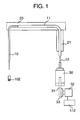
- Fig. 1 is a schematic view showing an embodiment in the present chemical analysis apparatus.
- a probe 10 is fixed to a probe arm 20, and is rotated and vertically moved by an arm rotating rod 21.
- a pump 30, for example, a syringe pump is piped to the probe 10 via a tube 11.
- a flow resistance portion 12 constituted by a narrow diameter tube is connected to the connection portion between the tube 11 and the syringe pump 30.
- a system water such as a pure water or the like is filled as a working fluid in the tube.
- a plunger 31 is moved by a pulse motor 32 via a transmission mechanism 33 such as a belt, a rack and pinion or the like.
- the pulse motor 32 is controlled by a controller 112.
- the probe is structured such that the inner diameter is 0.8 mm, the outer diameter is 1.2 mm, the length is 20 cm, and the material is SUS having a good chemical resistance, however, is not limited to this.
- the tube may be constituted by a resin tube having a good chemical resistance, and having an inner diameter of 1.5 mm, an outer diameter of 2.3 mm, a length of 2 m; the material may preferably be a polyfluoroethylene (a polytetrafluoroethylene, PTFE).
- the flow resistance portion 12 such as the narrow tube or the like having a smaller cross-sectional area than the tube 11 in the probe arm 20 portion is provided in the tube 11 corresponding to the pipe positioned between the probe arm 20 and the syringe pump 30.
- the flow resistance portion since it is possible to obtain the effect that the energy of a pulsation generated in the course of feeding a solution by the pump gets scattered and lost by the flow control means, here the flow resistance portion, by arranging that flow resistance portion in the way of the tube, the pulsation in the discharge port can be lowered, and a water hammer can be prevented or reduced, and the pipetting accuracy can be improved.
- flow control means here the narrow pipe
- flow control means are arranged at the upstream side in the piping path from the pump to the leading end of the probe.
- the narrow pipe in the area between the probe arm portion and the pump, whereby it is possible to lower the water hammer and to improve the pipetting accuracy.
- the probe arm portion generally comprises a resin tube which has a fixed rigidity so as to make the arm be easily driven, and is made of polyfluoroethylene (polytetrafluoroethylene, PTFE), however, in the case that a high pressure is applied, the tube may be deformed, leading to a greater pulsation generated by the syringe pump.
- polyfluoroethylene polytetrafluoroethylene
- the pulsation generated by the syringe pump is lowered before being input to the resin tube.
- the amplitude of the pulsation is increased. If the placing portion of the flow resistance portion 12 is at the quarter time distance of the wavelength of the pulsation from the leading end of the probe, it is possible to reduce the magnitude of the amplitude in the discharge port at the leading end of the probe at the time of pulsation. Further, if the placing portion is further closer to the syringe pump, it is possible to inhibit the resonance amplitude of the entire fluid system.
- the wavelength of the pulsation can be easily calculated on the basis of the entire length of the pipetting diameter of the fluid system.
- connection portion is provided in the way of the tube. In the same manner, in the case of placing the connection portion in front of the probe, there is generated a further problem.
- the solution enters into the tube from the probe due to an increase of the suction amount.
- the sucked solution passes through only the connection portion between the probe and the tube conventionally, however, in the case that the flow resistance portion is arranged in front of the probe, the solution passes through in total two connection portions among the probe, the resistance portion and the tube, so that the solution tends to be left.
- the cross-sectional area of the pipe is equal to or less than 99/100 the cross sectional area of the tube 11 in the probe arm 20, and the length of the pipe is equal to or less than 1/5 the length of the tube 11 in the probe arm 20. Since the fluid passes through such a level of narrow pipe, the flow is changed in the connection portion between the tube 11 of the probe arm portion 20 and the narrow pipe and a resistance is generated, so that it is possible to provide the effect that the energy of a pulsation is scattered and dissipated.
- the pressure loss is increased, so that there is the risk that the static pressure of the fluid becomes equal to or less than the saturated vapor pressure, and cavitation is generated lowering the pipetting accuracy.
- the static pressure of the fluid is determined in accordance with the flow rate and the shape of the fluid system, the static pressure is different in correspondence to the apparatus, however, it is preferable that the cross-sectional area of the narrow pipe is equal to or more than 1/100 the cross-sectional area of the tube 11, and the length of the narrow pipe is equal to or more than 1/1000 the length of the tube 11. Accordingly, it is possible to prevent the pressure loss from being increased more than unavoidable.
- Fig. 2 is a general schematic view showing the structure of a chemical analysis apparatus in accordance with the present embodiment.
- the present chemical analysis apparatus is provided, for example, with a plurality of reaction vessels 102 each having an upper opening portion, pipetting mechanisms 107 and 108 corresponding to a supplying mechanism for supplying a sample and a reagent from the opening portion, and a photometric mechanism 110 corresponding to measuring means for measuring physical properties of the sample which is under reaction or has ended the reaction.
- pipetting mechanisms 107 and 108 corresponding to a supplying mechanism for supplying a sample and a reagent from the opening portion
- a photometric mechanism 110 corresponding to measuring means for measuring physical properties of the sample which is under reaction or has ended the reaction.
- the chemical analysis apparatus is constituted by a reaction disc 101 for mainly storing the reaction vessel 102, a constant temperature bath 114 for keeping a constant temperature state of the reaction vessel stored in the reaction disc 101, a sample turntable 103 for receiving a sample vessel 104, a reagent turntable 105 for storing a reagent bottle 106, the sampling pipetting mechanism 107 for pipetting the sample and the reagent to the respective reaction vessels, the reagent pipetting mechanism 108, an agitating mechanism 109 for agitating the pipetted sample and reagent within the reaction vessel, the photometric mechanism 110 for measuring the absorbance in the process of reaction of the mixed materials within the reaction vessel and/or after the reaction, and a cleaning mechanism 111 for cleaning the reaction vessel after the test (the photometry) is finished.
- Each of the constituting elements is operated in accordance with a program automatically provided by a controller 112 on the basis of information (analysis items and volume to be analyzed) previously set through a console 113 before starting the test.
- the probe arm 20 and the probe arm 21 execute a rotational motion and a vertical motion, whereby the probe 10 is dipped into the sample cup 104 in which the sample is contained and the reagent bottle 106 in which the reagent is contained, and thereafter the plunger 31 is moved downward by the controller 112, and sucks the sample into the probe 10. Successively, the probe arm 20 and the probe arm 21 again execute the rotational motion and the vertical motion so as to move to the above of the reaction vessel 102, and thereafter the plunger 31 is moved upward and discharges the sample and the reagent within the probe into the reaction vessel 102.
- the plunger rapidly moves in the initial operation for discharging in the plunger, whereby a water hammer is generated.
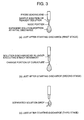
- Fig. 3 as a first stage, there is a case that when a high pressure small amount of solution within the probe is rapidly exposed to the atmosphere by the impact force of the water hammer, the small amount of solution is not discharged due to the strong surface tension in the resting state of the small amount of solution at the leading end of the probe even by being fed at the high pressure, so that the volume of the solution is rapidly increased.
- the discharged solution is reduced, so that it is possible to inhibit the pipetting accuracy from being lowered and it is possible to inhibit the broken solution from being scattered to the periphery so as to contaminate the apparatus.
- the portion in which the solution break is generated depends greatly upon physical properties such as the viscosity, the wettability and the like of the discharged sample or reagent, the portion changed every discharging time, however, the present embodiment can inhibit the risk that the pipetting accuracy is lowered due to the change of the discharging amount.
- the present embodiment is preferable for designing an analysis apparatus provided with a mechanism of pipetting at a high speed. For example, when discharging at a high speed, the water hammer caused by the rapid stop of the plunger is further enlarged, the possibility that the solution is scattered due to the solution break is higher, and there is the problem that the pipetting accuracy is greatly lowered.
- FIGs. 5(a) and 5(b) A transient pressure fluctuation at this time is shown by Figs. 5(a) and 5(b).
- the case in accordance with a comparative embodiment which does not employ the present embodiment is shown by a broken line, and the case using the structure shown by the present embodiment is shown by a solid line.
- the pressure shows a water hammer phenomenon such as the overshoot and the "returning" thereof as illustrated, the solution is discharged at an excessive amount as mentioned in the problem to be solved by the invention, and problems such as the solution break or the like are further generated.
- the portion generating the fluid flow resistance can be concentrated to a portion near the syringe pump corresponding to the pressure source.
- the method of placing an orifice it is conceivable to employ the method of placing an orifice, however, the aspect of easily inserting the narrow pipe is desirable.
- the narrow pipe having a length of 10 mm and an inner diameter of 1 mm is inserted. Since the inner diameter is within the limit of the cross-sectional area with respect to the other tube diameter 1.5 mm such as the probe arm 20, the wave form of the pressure is as shown by the solid lines in Figs. 5(a) and 5(b), the influence of the water hammer such as the overshoot and the "returning" thereof breaks down, it is possible to inhibit the discharge at an excessive amount, and a solution break is hard to be generated.
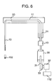
- FIG. 6 Another embodiment is shown in Fig. 6.
- the embodiment in Fig. 6 can basically have the same structure as that in Fig. 1 mentioned above, however, the embodiment in Fig. 6 is characterized in that an expanded area having a larger cross-sectional area than that of the tube 11 in the probe arm 20 is provided in a pipe positioned between the probe arm 20 and the syringe pump 30, in place of the flow resistance portion 12 mentioned above.
- a pipe having an inner diameter of about 5 mm and a length of about 10 mm can be connected as a volumetric capacity portion 13 having a fixed capacity and arranged in the connecting portion of the tube to the syringe pump, however, the structure is not limited to this.
- the cross-sectional area of the volumetric capacity portion 13 corresponding to the expanded area is equal to or more than 101/100 times the cross-sectional area of the tube 11 in the probe arm 20 and 1/1000 times the length, and it is preferable that the cross-sectional area is equal to or more than 5/4 times, and the length is equal to or more than 1/500 times. This is because the capacity is the minimum capacity which can absorb the vibration energy contained in the fluid and can be scattered and dissipated.
- the cross-sectional area is equal to or less than 10 times and the length is equal to or less than 1/5, and the cross-sectional area is equal to or less than twice and the length is equal to or less than 1/10, for the purpose of preventing the pressure fluctuation from being propagated into the volumetric capacity portion from the syringe pump so as to lower the response of the fluid system. Accordingly, it is possible to save an amount of the pure water consumed in the fluid system. It is desirable that the installation position is at a distance 1/4 times the wavelength of the pulsation from the leading end of the probe, and near the syringe portion.
- any other embodiment is shown in Fig. 7.
- the embodiment in Fig. 7 can basically have the same structure as that in Fig. 1 mentioned above, however, the embodiment in Fig 7 is characterized in that an elastic portion 14 is provided in the pipe positioned between the probe arm 20 and the syringe pump 30, in place of the flow resistance portion 12 and the volumetric capacity portion 13 mentioned above as flow control means.
- an elastic area structured by a material having a lower elastic modulus in tension than the probe and having a rigidity in the range of the elastic modulus in tension between 100 and 3000 kgf/cm 2 (981 N/cm 2 and 29.4 kN/cm 2 ) is provided in the pipe positioned between the probe arm portion and the pump portion.
- an elastic pipe constituted by a resin tube having a rigidity in the range of the elastic modulus in tension between 100 and 3000 kgf/cm 2 (981 N/cm 2 and 29.4 kN/cm 2 ).
- a tigon tube having an elastic modulus of tension of 1570 N/cm 3 (160 kgf/cm 2 ) and a length of about 50 mm.
- the tube 11 is a resin tube having a comparatively high elastic modulus of tension of about 343 kN/cm 3 (about 3500 kgf/cm 2 ) such as a polyfluoroethylene (polytetrafluoroethylene) tube or the like.
- the water hammer of the syringe pump and the energy of the pulsation are propagated as it is to the leading end of the probe, and the pipetting solution tends to be discharged at an excess amount and the solution break tends to occur. Accordingly, by inserting the elastic pipe having the elastic modulus in tension equal to or less than 29.4 kN/cm 2 (3000 kgf/cm 2 ), the elastic pipe is deformed at the time when the pressure is propagated to the inserted elastic pipe, so that it is possible to obtain the effect that the water hammer and the pressure of the pulsation can be consumed by the deformation of the elastic pipe.
- the elastic modulus of the elastic pipe for example, in the case of a resin tube such as a silicone tube or the like having a comparatively low rigidity in which the elastic modulus in tension is about 589 N/cm 2 (60 kgf/cm 2 ), a great deformation such as a flat shape of the tube is generated in the case that a high pressure is applied at the time of discharging. In the extreme case, the tube collapses, and the fluid can not flow. Accordingly, it is desirable that the elastic modulus in tension is equal to or more than 981 N/cm 2 (100 kgf/cm 2 ).
- the elastic area includes a position at a distance 1/4 times the pulsation from the leading end of the probe or integral multiple areas.
- Fig. 8 is a schematic view showing an embodiment of the present chemical analysis apparatus.
- the probe 10 is fixed to the probe arm 20, and is rotated and vertically moved by the arm rotating rod 21.
- a high resolving power syringe pump portion 40 and a low resolving power syringe pump portion 41 are piped to the tube 11 via a valve 15 controlled by a controller 112.
- a plunger 401 of a syringe pump 400 is moved by a pulse motor 402 via a transmission mechanism 403 such as a belt, a rack and pinion and the like.
- the pulse motor 402 is controlled by the controller 112.
- a plunger 411 of a syringe pump 410 is moved by a pulse motor 412 via a transmission mechanism 413 such as a belt, a rack and pinion and the like.
- the pulse motor 412 is controlled by the controller 112.
- the syringe pump having a high resolving power listed here there may be mentioned a pencil-type pump having a small discharge resolving power 0.02 ⁇ l/P, and manufactured by Uniflows Co., Ltd, and the like, however, the syringe pump is not limited to this.
- a syringe pump having a resolving power of about 0.1 ⁇ l/P can be used as the low resolving power syringe pump.
- the pumps for example syringe pumps, are piped to the probe 10 via the tube 11.
- Flow control means such as a flow resistance portion 12 constituted by a narrow diameter pipe may be connected to the connection portion between the tube 11 and the pumps or the valve 15.
- a system water such as a pure water or the like is filled in the tube.
- the structure in accordance with the present embodiment is provided with the syringe pump portion 40 corresponding to the high resolving power first pump 400, 401 which is communicated with the probe 10 via the tube 11 formed in the probe arm 20, and on the other hand is provided with the syringe pump portion 41 corresponding to the low resolving power second pump 410, 411 via a changing valve 15 corresponding to the branch portion. Further, these pumps are selectively used in correspondence to the discharge flow rate from the probe 10.
- control is executed in such a manner as to discharge solution at a first flow rate from the probe 10 by driving the syringe pump portion 41, and to discharge solution at a second flow rate greater than the first flow rate by driving the syringe pump portion 40.
- the basic operation that the reagent and the sample are sucked and discharged by the probe 10 is the same as that shown in the first embodiment.
- the high resolving power syringe pump portion 40 is used.
- the low resolving power syringe pump portion 41 is used.
- the high resolving power syringe pump portion 40 is driven at a low speed at the time of starting, and is driven at a high speed after a certain time has passed.
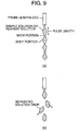
- the transient pressure fluctuation at this time is as shown in Fig. 9.
- the case that the low resolving power syringe pump portion 41 is used when the flow rate is small is shown as a comparative embodiment by a broken line, and the case that the high resolving power syringe pump portion 40 shown in the present embodiment is used is shown by a solid line. In the case of using the low resolving power syringe pump portion 41, the discharging amount per one pulse is large.
- the inventors of the present application have made a study on countermeasures against the pulsation of the pressure and the flow rate which are generated due to the change in pulse of the discharging pressure, in the steady state during discharging. It was found that in the case that the pulsation is generated, a node portion and a body portion are generated in the sample and the reagent which are discharged from the probe, in the same manner as in the case where the water hammer is generated at the time of starting the discharge, as shown in Fig. 9, the solution break tends to be generated in the boundary portion between the node portion and the body portion in which the curvature changes, and the broken solution is scattered to the periphery, whereby there is the risk that the broken solution contaminates the apparatus. Further, it has been found that in the case that the solution is scattered to other portions than the measurement vessel, the amount of discharged solution is reduced, whereby there is the risk that the pipetting accuracy is lowered.
- the control is executed in such a manner that the supply of the solution from the probe 10 is started by the pump having the low discharge resolving power, after starting the discharge of the solution from the probe 10 by the pump having the high discharge resolving power.
- the pump having the high discharge resolving power is driven for the initial operation of the solution discharge from the probe 10, and thereafter, the operation is switched to the pump having the low discharge resolving power.
- the solution is discharged by again switching to the pump having the high discharge resolving power at the end of the solution discharge, after the operation by the pump having the low discharge resolving power.
- the pump is switched in the steady state in the course of the discharge as in the present embodiment, it is possible to inhibit the large pulsation which is generated due to pumping at low resolving power. Accordingly, the length between the node portion and the body portion formed in the sample or the reagent discharged from the probe, the so-called pulse length, becomes short, and the break between the node portion and the body portion is hard to be distinguished, whereby it is possible to practically suppress the solution break.
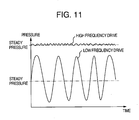
- Fig. 11 shows wave forms of the discharge pressure in the steady state, in the case that the low resolving power pump is driven at the high flow rate, that is, the high frequency, and in the case that the low resolving power pump is driven at the low flow rate, that is, the low frequency.
- the low resolving power syringe pump is driven at the low frequency by the pulse motor.
- the pulse interval up to the next applied pulse is long, whereby the flow rate is lowered and the pressure is lowered. Therefore, the oscillation of the pressure is increased.
- the oscillation of the pressure is lowered. Accordingly, the solution break is hard to be generated.
- the solution is fed by the high resolving power syringe pump in the case of the low flow rate, and the solution is thereafter fed by the low resolving power syringe pump, it is possible to make the pulsation of the pressure and the flow rate in the steady state in the course of the discharging smaller. Accordingly, it is possible to provide a chemical analysis apparatus in which the pipetting accuracy is high, and sample and reagent are not scattered.
- the low resolving power syringe pump is operated in the case of the large flow rate by switching the valve, and it is possible to make the pulsation of the pressure and the flow rate in the steady state in the course of the discharging smaller at this time, it is possible to provide a chemical analysis apparatus in which the pipetting accuracy is high, and sample and reagent are not scattered.
Landscapes
- Health & Medical Sciences (AREA)
- Chemical & Material Sciences (AREA)
- General Health & Medical Sciences (AREA)
- General Physics & Mathematics (AREA)
- Life Sciences & Earth Sciences (AREA)
- Pathology (AREA)
- Analytical Chemistry (AREA)
- Biochemistry (AREA)
- Immunology (AREA)
- Physics & Mathematics (AREA)
- Engineering & Computer Science (AREA)
- Quality & Reliability (AREA)
- Clinical Laboratory Science (AREA)
- Chemical Kinetics & Catalysis (AREA)
- Automatic Analysis And Handling Materials Therefor (AREA)
- Sampling And Sample Adjustment (AREA)
Abstract
Description
- a probe portion for sucking and discharging the solution;
- a probe arm portion communicated with the probe portion and moving the probe portion to the reagent vessel or the sample vessel and the reaction vessel; and
- a pump to which a pipe is connected, the pipe being communicated with the pump and with the probe portion via the probe arm portion, and
- 10
- probe portion
- 11
- tube (pipe)
- 12
- flow control means
- 13
- volumetric capacity portion (enlarged area portion)
- 14
- elastic area portion
- 15
- valve
- 20
- probe arm
- 21
- arm rotating rod
- 30
- pump
- 31
- plunger
- 32
- pulse motor
- 33
- transmission mechanism
- 40
- syringe pump portion (high resolving power)
- 41
- syringe pump portion (low resolving power)
- 101
- reaction disc
- 102
- reaction vessel
- 103
- sample turntable
- 104
- sample vessel (sample cup)
- 105
- reagent turntable
- 106
- reagent bottle
- 107
- pipetting mechanism
- 108
- pipetting mechanism
- 109
- agitating mechanism
- 110
- photometric mechanism
- 111
- cleaning mechanism
- 112
- controller
- 113
- console
- 114
- constant temperature bath
- 400
- pump
- 401
- plunger
- 402
- pulse motor
- 403
- transmission mechanism
- 410
- pump
- 411
- plunger
- 412
- pulse motor
- 413
- transmission mechanism
Claims (12)
- Chemical analysis apparatus, comprising:characterized in thata reagent vessel (106) provided with a reagent solution,a sample vessel (104) provided with a sample solution,a reaction vessel (102) to which the reagent and the sample are supplied,a reagent supplying mechanism (107) for supplying the reagent to the reaction vessel (102), anda sample supplying mechanism (108) for supplying the sample to the reaction vessel (102),wherein at least one of the reagent supplying mechanism (107) and the sample supplying mechanism (108) comprises:a probe portion (10) for sucking and discharging the solution,a probe arm portion (20) communicated with the probe portion (10) and moving the probe portion (10) to the reagent vessel (106) or the sample vessel (104) and the reaction vessel (102), anda pump (30) connected to the probe portion (10) via a pipe (11) provided in the probe arm portion (20),
flow control means (12; 13; 14; 40; 41) are provided in the pipe (11) positioned between the probe arm portion (20) and the pump portion (30). - Chemical analysis apparatus according to claim 1, characterized in that the flow control means are a narrow area portion (12) having a smaller cross-sectional area than the pipe (11) in the probe arm portion (20).
- Chemical analysis apparatus according to claim 1 or 2 characterized in that the flow control means are a flow resistance portion (12) having a higher flow path resistance than the pipe (11) in the probe arm portion (20) .
- Chemical analysis apparatus according to any of claims 1 to 3, characterized in that the flow control means are an enlarged area portion (13) having a larger cross-sectional area than the pipe (11) in the probe arm portion (20).
- Chemical analysis apparatus according to any of claims 1 to 4, characterized in that the flow control means are an elastic area portion (14) structured with a material having a lower elastic modulus in tension than the probe (10) and has a rigidity of the elastic modulus in tension of 981 N/cm2 to 29.4 kN/cm2 (100 to 3000 kgf/cm2).
- Chemical analysis apparatus according to any of claims 2 to 5, characterized in that a portion having a large cross-sectional area in the narrow area portion (12) is provided closer to the pump (30) than to the narrow area portion (12).
- Chemical analysis apparatus according to any of claims 1 to 6, wherein the pump and the flow control means are designed such that they comprise:the first pump portion (40) has a higher discharge resolving power than the second pump portion (41), and the pump portions (40, 41) being adapted to be controlled in such a manner as to supply solution from the probe (10) at a first flow rate by driving the second pump portion (41) and to supply the solution at a second flow rate greater than the first flow rate by driving the first pump portion (40).a first pump portion (40) to which a pipe is connected, the pipe communicating the first pump portion (40) with the probe portion (10) via the probe arm portion (20),
anda second pump portion (41) communicated with the pipe at the upstream side of the probe arm portion (20) via a branch portion (15), wherein - Chemical analysis apparatus according to claim 7, being adapted to be controlled in such a manner as to start supplying the solution from the probe portion (10) by the first pump portion (40) after starting supplying the solution from the probe (10) by the second pump portion (41).
- Chemical analysis apparatus, comprising:wherein the first pump portion (40) has a higher discharge resolving power than the second pump portion (41), and the pump portions (40, 41) being adapted to be controlled in such a manner as to supply solution from the probe portion (10) at a first flow rate by driving the second pump portion (41) and to supply the solution at a second flow rate greater than the first flow rate by driving the first pump portion (40).a reagent vessel (106) provided with a reagent solution,a sample vessel (104) provided with a sample solution,a reaction vessel (102) to which the reagent and the sample are supplied,a reagent supplying mechanism (107) for supplying the reagent to the reaction vessel (102),
anda sample supplying mechanism (108) for supplying the sample to the reaction vessel (102),wherein at least one of the reagent supplying mechanism (107) and the sample supplying mechanism (108) comprises:a probe portion (10) for sucking and discharging the solution,a probe arm portion (20) communicated with the probe portion (10) and moving the probe portion (10) to the reagent vessel (106) or the sample vessel (104) and the reaction vessel (102),a first pump portion (40) to which a pipe is connected, the pipe communicating the first pump portion (40) with the probe portion (10) via the probe arm portion (20),
anda second pump portion (41) communicated with the pipe at the upstream side of the probe arm portion (20) via a branch portion (15), - Chemical analysis apparatus according to claim 9, being adapted to be controlled in such a manner as to start supplying the solution from the probe portion (10) by the first pump portion (40) after starting supplying the solution from the probe (10) by the second pump portion (41).
- Chemical analysis apparatus according to any of claims 7 to 10,
wherein a three-way valve (15) is provided at the upstream side of the pipe (11) connected to the first pump portion (40) and to the second pump portion (41). - Chemical analysis apparatus according to any of claims 1 to 11, further comprising a controller (112) for controlling the operation of the apparatus, particularly the operation of the pump (30) or the operation of the pump portions (40, 41), respectively.
Applications Claiming Priority (2)
| Application Number | Priority Date | Filing Date | Title |
|---|---|---|---|
| JP2003027752A JP3903015B2 (en) | 2003-02-05 | 2003-02-05 | Chemical analyzer |
| JP2003027752 | 2003-02-05 |
Publications (3)
| Publication Number | Publication Date |
|---|---|
| EP1447669A2 true EP1447669A2 (en) | 2004-08-18 |
| EP1447669A3 EP1447669A3 (en) | 2004-11-10 |
| EP1447669B1 EP1447669B1 (en) | 2009-11-18 |
Family
ID=32677565
Family Applications (1)
| Application Number | Title | Priority Date | Filing Date |
|---|---|---|---|
| EP04002600A Expired - Lifetime EP1447669B1 (en) | 2003-02-05 | 2004-02-05 | Chemical analysis apparatus |
Country Status (4)
| Country | Link |
|---|---|
| US (1) | US20040156748A1 (en) |
| EP (1) | EP1447669B1 (en) |
| JP (1) | JP3903015B2 (en) |
| DE (1) | DE602004024147D1 (en) |
Cited By (4)
| Publication number | Priority date | Publication date | Assignee | Title |
|---|---|---|---|---|
| EP1745851A1 (en) * | 2005-07-22 | 2007-01-24 | Tecan Trading AG | Process, device and computerprogramm product for the classification of a liquid |
| US7830520B2 (en) | 2006-04-03 | 2010-11-09 | Shimadzu Corporation | Optical measurement device for trace liquid sample |
| WO2010132887A3 (en) * | 2009-05-15 | 2011-02-17 | Gen-Probe Incorporated | Contamination control for liquid handling |
| US8662392B2 (en) | 2010-11-12 | 2014-03-04 | Gen-Probe Incorporated | System and method for tracking items during a process |
Families Citing this family (15)
| Publication number | Priority date | Publication date | Assignee | Title |
|---|---|---|---|---|
| JP4618001B2 (en) * | 2005-05-25 | 2011-01-26 | 株式会社安川電機 | Automatic chemical analyzer |
| US20100242630A1 (en) * | 2007-08-05 | 2010-09-30 | Al-Qassem Sadeq Ahmad | Sample extraction device |
| JP2010175441A (en) * | 2009-01-30 | 2010-08-12 | Toshiba Corp | Automatic analyzer |
| JP5329368B2 (en) * | 2009-10-26 | 2013-10-30 | 日本電子株式会社 | Probe vibration control device |
| JP5277214B2 (en) * | 2010-07-27 | 2013-08-28 | 株式会社日立ハイテクノロジーズ | Automatic analyzer |
| US9588132B2 (en) | 2011-04-08 | 2017-03-07 | Artel, Inc. | Validation method for automated analyzers |
| JP5835924B2 (en) * | 2011-04-08 | 2015-12-24 | 晃 服部 | Automatic analyzer verification method |
| JP5357223B2 (en) * | 2011-08-24 | 2013-12-04 | 株式会社鷺宮製作所 | Capillary viscometer |
| US9970868B2 (en) * | 2013-08-22 | 2018-05-15 | Becton, Dickinson And Company | Nephelometry method and apparatus for determining the concentration of suspended particles in an array of sample containers |
| CN104062150B (en) * | 2014-07-07 | 2015-04-22 | 中国水产科学研究院黄海水产研究所 | Electric duckbill low-flow-velocity settling collection device |
| US10379130B2 (en) | 2015-06-26 | 2019-08-13 | Abbott Laboratories | Reaction vessel exchanger device for a diagnostic analyzer |
| EP3599456B1 (en) * | 2017-03-31 | 2025-06-11 | Sony Group Corporation | Channel unit and microparticle analysis device |
| CN107449720A (en) * | 2017-08-14 | 2017-12-08 | 中生(苏州)医疗科技有限公司 | A kind of separate type system for pretreating sample with discharging to connection function |
| JP7470970B2 (en) * | 2020-04-28 | 2024-04-19 | マッスル株式会社 | Pipetting and Analytical Equipment |
| JP2025002374A (en) * | 2023-06-22 | 2025-01-09 | 株式会社日立ハイテク | Automated Analysis Equipment |
Family Cites Families (39)
| Publication number | Priority date | Publication date | Assignee | Title |
|---|---|---|---|---|
| JPS523662A (en) * | 1975-06-27 | 1977-01-12 | Asahi Glass Co Ltd | Method of filament winding |
| JPS55121151A (en) * | 1979-03-12 | 1980-09-18 | Olympus Optical Co Ltd | Diluting equipment |
| JPS55136957A (en) * | 1979-04-14 | 1980-10-25 | Olympus Optical Co Ltd | Automatic analyzer |
| GB2057291A (en) * | 1979-08-31 | 1981-04-01 | Hackett W J | Safety pipette filler |
| JPS56135160A (en) * | 1980-03-26 | 1981-10-22 | Hitachi Ltd | Divided injection device for liquid |
| JPS5868670A (en) * | 1981-10-21 | 1983-04-23 | Hitachi Ltd | automatic fractionator |
| US4563175A (en) * | 1983-12-19 | 1986-01-07 | Lafond Margaret | Multiple syringe pump |
| US4675301A (en) * | 1985-04-01 | 1987-06-23 | Eastman Kodak Company | Method for correcting for changes in air pressure above a liquid to be dispensed from a container mounted on a probe |
| JPS623662A (en) * | 1985-06-28 | 1987-01-09 | Toshiba Corp | Dispenser |
| JPS6264912A (en) * | 1985-09-17 | 1987-03-24 | Minoru Atake | Distributive injection apparatus |
| JPH0212598Y2 (en) * | 1985-11-09 | 1990-04-09 | ||
| JPS62228953A (en) * | 1986-03-31 | 1987-10-07 | Toshiba Corp | Automatic chemical analyzer |
| JPS6388458A (en) * | 1986-10-02 | 1988-04-19 | Olympus Optical Co Ltd | Tube connector for solid-phase conversion reagent producing equipment |
| JP2839560B2 (en) * | 1989-07-10 | 1998-12-16 | 株式会社日立製作所 | Particle suspension mixing device, particle suspension mixing method, and particle measuring device |
| JPH0382965A (en) * | 1989-08-26 | 1991-04-08 | Shimadzu Corp | Biochemical automatic analyzer |
| DE69117564T2 (en) * | 1990-04-18 | 1996-08-08 | Du Pont | Device for taking samples from open and closed containers |
| JPH04125468A (en) * | 1990-09-17 | 1992-04-24 | Toshiba Corp | Dispenser |
| JPH04274764A (en) * | 1991-03-01 | 1992-09-30 | Mitsubishi Kasei Eng Co | Method for controlling dispensing in sample dispensing device |
| JPH04296655A (en) * | 1991-03-26 | 1992-10-21 | Mochida Pharmaceut Co Ltd | Method for measuring liquid, and method and device for automatic dispenser using the same |
| JPH0694730A (en) * | 1992-01-16 | 1994-04-08 | Hitachi Ltd | Dispensing device to prevent reagent liquid adhesion |
| JP3318629B2 (en) * | 1993-06-18 | 2002-08-26 | ソニー株式会社 | Liquid suction / discharge device and method |
| JP3339177B2 (en) * | 1994-04-27 | 2002-10-28 | 株式会社島津製作所 | Dispensing device |
| JPH07333230A (en) * | 1994-06-06 | 1995-12-22 | Hitachi Ltd | Liquid dispensing device and automatic analyzer using the same |
| JP3282455B2 (en) * | 1994-07-28 | 2002-05-13 | 株式会社日立製作所 | Liquid sampling method and device |
| JPH08114601A (en) * | 1994-10-18 | 1996-05-07 | Hitachi Ltd | Multi-item inspection and analysis device for liquid samples |
| JPH08297121A (en) * | 1995-04-26 | 1996-11-12 | Hitachi Ltd | Particle analyzer |
| JPH08313540A (en) * | 1995-05-16 | 1996-11-29 | Hitachi Ltd | Clinical biochemistry analyzer |
| US5915282A (en) * | 1995-12-14 | 1999-06-22 | Abbott Laboratories | Fluid handler and method of handling a fluid |
| US5965828A (en) * | 1995-12-14 | 1999-10-12 | Abbott Laboratories | Fluid handler and method of handling a fluid |
| US5723795A (en) * | 1995-12-14 | 1998-03-03 | Abbott Laboratories | Fluid handler and method of handling a fluid |
| JPH10239323A (en) * | 1997-02-24 | 1998-09-11 | Hitachi Ltd | Automatic dispensing device |
| JP3704425B2 (en) * | 1997-09-24 | 2005-10-12 | オリンパス株式会社 | Automatic analyzer |
| JP3418329B2 (en) * | 1998-02-09 | 2003-06-23 | 株式会社日立製作所 | Sample dispensing method and automatic analyzer |
| JPH11271329A (en) * | 1998-03-25 | 1999-10-08 | Hitachi Ltd | Automatic analyzer |
| US6261847B1 (en) * | 1998-07-10 | 2001-07-17 | Bayer Corporation | Sample dilution module with offset mixing chamber |
| JP2000121649A (en) * | 1998-10-09 | 2000-04-28 | Furuno Electric Co Ltd | Automatic dispensing device |
| JP2001264341A (en) * | 2000-03-17 | 2001-09-26 | Olympus Optical Co Ltd | Liquid dispensing device |
| US6370942B1 (en) * | 2000-05-15 | 2002-04-16 | Dade Behring Inc. | Method for verifying the integrity of a fluid transfer |
| JP3793477B2 (en) * | 2002-03-28 | 2006-07-05 | オリンパス株式会社 | Dispensing device |
-
2003
- 2003-02-05 JP JP2003027752A patent/JP3903015B2/en not_active Expired - Fee Related
-
2004
- 2004-02-04 US US10/770,518 patent/US20040156748A1/en not_active Abandoned
- 2004-02-05 EP EP04002600A patent/EP1447669B1/en not_active Expired - Lifetime
- 2004-02-05 DE DE602004024147T patent/DE602004024147D1/en not_active Expired - Lifetime
Cited By (11)
| Publication number | Priority date | Publication date | Assignee | Title |
|---|---|---|---|---|
| EP1745851A1 (en) * | 2005-07-22 | 2007-01-24 | Tecan Trading AG | Process, device and computerprogramm product for the classification of a liquid |
| US8357544B2 (en) | 2005-07-22 | 2013-01-22 | Tecan Trading Ag | Method for selecting pipetting parameters for a liquid |
| US7830520B2 (en) | 2006-04-03 | 2010-11-09 | Shimadzu Corporation | Optical measurement device for trace liquid sample |
| WO2010132887A3 (en) * | 2009-05-15 | 2011-02-17 | Gen-Probe Incorporated | Contamination control for liquid handling |
| US8309036B2 (en) | 2009-05-15 | 2012-11-13 | Gen-Probe Incorporated | Method for separating viscous materials suspended from a pipette |
| US8790593B2 (en) | 2009-05-15 | 2014-07-29 | Gen-Probe Incorporated | Contamination control for liquid handling |
| US8939364B2 (en) | 2009-05-15 | 2015-01-27 | Gen-Probe Incorporated | Contamination control for liquid handling |
| US9011802B2 (en) | 2009-05-15 | 2015-04-21 | Gen-Probe Incorporated | Covered rack for holding fluid receptacles |
| US9117192B2 (en) | 2009-05-15 | 2015-08-25 | Gen-Probe Incorporated | Method for reading machine-readable labels |
| US8662392B2 (en) | 2010-11-12 | 2014-03-04 | Gen-Probe Incorporated | System and method for tracking items during a process |
| US9171279B2 (en) | 2010-11-12 | 2015-10-27 | Gen-Probe Incorporated | Receptacle rack having an electronic memory element |
Also Published As
| Publication number | Publication date |
|---|---|
| JP3903015B2 (en) | 2007-04-11 |
| US20040156748A1 (en) | 2004-08-12 |
| EP1447669A3 (en) | 2004-11-10 |
| DE602004024147D1 (en) | 2009-12-31 |
| JP2004239697A (en) | 2004-08-26 |
| EP1447669B1 (en) | 2009-11-18 |
Similar Documents
| Publication | Publication Date | Title |
|---|---|---|
| EP1447669B1 (en) | Chemical analysis apparatus | |
| EP0107333B1 (en) | Apparatus and method for supply of sample and sheath liquids to analytical flow cell | |
| JP5122949B2 (en) | Dispensing amount detection method and liquid absorption monitor type dispensing device | |
| JP6647264B2 (en) | Cartridge for supplying fluid | |
| EP2634586B1 (en) | Automatic analysis device | |
| US20030167822A1 (en) | Univeral calibration system and method for a high performance, low volume, non-contact liquid dispensing apparatus | |
| JP5587965B2 (en) | Chemical analyzer | |
| EP0825446B1 (en) | Pipette-washing device for automatic biochemical analyzer | |
| KR20130064063A (en) | Discharge device and liquid dispensing device, and method for dispensing liquid | |
| JP7660240B2 (en) | Liquid Dispensing Device | |
| JPH10227799A (en) | Dispensing device | |
| US12504437B2 (en) | Automatic analysis device | |
| JP7751385B2 (en) | Liquid distribution system for microfluidic sample carriers, a microfluidic sample carrier sealing system including such a liquid distribution system, and a method for dispensing sealing liquid using the same | |
| EP3785034B1 (en) | Intelligent pressure control apparatus and methods for maintaining manifold pressure in a diagnostic testing apparatus | |
| JP2009162536A (en) | Liquid sample dispensing apparatus and driving method | |
| US20250044314A1 (en) | Automated analyzing device, and dispensing method | |
| KR20230034352A (en) | Dispensing device and method | |
| JP2003149093A (en) | Liquid dispensing apparatus and liquid dispensing method | |
| JP7278199B2 (en) | automatic analyzer | |
| JPH10115622A (en) | Dispensing device | |
| WO2025197542A1 (en) | Automatic analysis device | |
| JP2007278835A (en) | Dispensing device and method | |
| JP2009139238A (en) | Liquid vessel, and automatic analyzer | |
| JP2020515842A (en) | Method and metering device for contact liquid measurement | |
| JP4363964B2 (en) | Dispensing device |
Legal Events
| Date | Code | Title | Description |
|---|---|---|---|
| PUAI | Public reference made under article 153(3) epc to a published international application that has entered the european phase |
Free format text: ORIGINAL CODE: 0009012 |
|
| AK | Designated contracting states |
Kind code of ref document: A2 Designated state(s): AT BE BG CH CY CZ DE DK EE ES FI FR GB GR HU IE IT LI LU MC NL PT RO SE SI SK TR |
|
| AX | Request for extension of the european patent |
Extension state: AL LT LV MK |
|
| PUAL | Search report despatched |
Free format text: ORIGINAL CODE: 0009013 |
|
| AK | Designated contracting states |
Kind code of ref document: A3 Designated state(s): AT BE BG CH CY CZ DE DK EE ES FI FR GB GR HU IE IT LI LU MC NL PT RO SE SI SK TR |
|
| AX | Request for extension of the european patent |
Extension state: AL LT LV MK |
|
| 17P | Request for examination filed |
Effective date: 20050301 |
|
| AKX | Designation fees paid |
Designated state(s): DE FR GB |
|
| 17Q | First examination report despatched |
Effective date: 20060928 |
|
| 17Q | First examination report despatched |
Effective date: 20060928 |
|
| GRAP | Despatch of communication of intention to grant a patent |
Free format text: ORIGINAL CODE: EPIDOSNIGR1 |
|
| GRAS | Grant fee paid |
Free format text: ORIGINAL CODE: EPIDOSNIGR3 |
|
| RIN1 | Information on inventor provided before grant (corrected) |
Inventor name: ENOKI, HIDEO Inventor name: YAMAZAKI, ISAO Inventor name: YAMAKAWA, HIRONOBU |
|
| GRAA | (expected) grant |
Free format text: ORIGINAL CODE: 0009210 |
|
| AK | Designated contracting states |
Kind code of ref document: B1 Designated state(s): DE FR GB |
|
| REG | Reference to a national code |
Ref country code: GB Ref legal event code: FG4D |
|
| REF | Corresponds to: |
Ref document number: 602004024147 Country of ref document: DE Date of ref document: 20091231 Kind code of ref document: P |
|
| PLBE | No opposition filed within time limit |
Free format text: ORIGINAL CODE: 0009261 |
|
| STAA | Information on the status of an ep patent application or granted ep patent |
Free format text: STATUS: NO OPPOSITION FILED WITHIN TIME LIMIT |
|
| 26N | No opposition filed |
Effective date: 20100819 |
|
| GBPC | Gb: european patent ceased through non-payment of renewal fee |
Effective date: 20100218 |
|
| PG25 | Lapsed in a contracting state [announced via postgrant information from national office to epo] |
Ref country code: GB Free format text: LAPSE BECAUSE OF NON-PAYMENT OF DUE FEES Effective date: 20100218 |
|
| REG | Reference to a national code |
Ref country code: FR Ref legal event code: PLFP Year of fee payment: 13 |
|
| PGFP | Annual fee paid to national office [announced via postgrant information from national office to epo] |
Ref country code: DE Payment date: 20160202 Year of fee payment: 13 |
|
| PGFP | Annual fee paid to national office [announced via postgrant information from national office to epo] |
Ref country code: FR Payment date: 20160108 Year of fee payment: 13 |
|
| REG | Reference to a national code |
Ref country code: DE Ref legal event code: R119 Ref document number: 602004024147 Country of ref document: DE |
|
| REG | Reference to a national code |
Ref country code: FR Ref legal event code: ST Effective date: 20171031 |
|
| PG25 | Lapsed in a contracting state [announced via postgrant information from national office to epo] |
Ref country code: DE Free format text: LAPSE BECAUSE OF NON-PAYMENT OF DUE FEES Effective date: 20170901 Ref country code: FR Free format text: LAPSE BECAUSE OF NON-PAYMENT OF DUE FEES Effective date: 20170228 |