KR20230034352A - Dispensing device and method - Google Patents
Dispensing device and method Download PDFInfo
- Publication number
- KR20230034352A KR20230034352A KR1020237003741A KR20237003741A KR20230034352A KR 20230034352 A KR20230034352 A KR 20230034352A KR 1020237003741 A KR1020237003741 A KR 1020237003741A KR 20237003741 A KR20237003741 A KR 20237003741A KR 20230034352 A KR20230034352 A KR 20230034352A
- Authority
- KR
- South Korea
- Prior art keywords
- dispensing
- chip
- pressure
- type
- liquid
- Prior art date
Links
- 238000000034 method Methods 0.000 title claims description 33
- 230000007246 mechanism Effects 0.000 claims abstract description 13
- 239000007788 liquid Substances 0.000 claims description 118
- 238000001514 detection method Methods 0.000 claims description 23
- 238000007599 discharging Methods 0.000 claims description 5
- 238000011109 contamination Methods 0.000 abstract description 7
- 238000010586 diagram Methods 0.000 description 13
- 230000008859 change Effects 0.000 description 10
- 238000012360 testing method Methods 0.000 description 8
- 238000012545 processing Methods 0.000 description 6
- 238000002474 experimental method Methods 0.000 description 3
- 230000006870 function Effects 0.000 description 3
- 230000015572 biosynthetic process Effects 0.000 description 2
- 230000008878 coupling Effects 0.000 description 2
- 238000010168 coupling process Methods 0.000 description 2
- 238000005859 coupling reaction Methods 0.000 description 2
- 230000002068 genetic effect Effects 0.000 description 2
- 238000007689 inspection Methods 0.000 description 2
- 239000000463 material Substances 0.000 description 2
- 238000012795 verification Methods 0.000 description 2
- 238000009825 accumulation Methods 0.000 description 1
- 230000009471 action Effects 0.000 description 1
- 238000004458 analytical method Methods 0.000 description 1
- 230000009172 bursting Effects 0.000 description 1
- 239000003153 chemical reaction reagent Substances 0.000 description 1
- 238000004140 cleaning Methods 0.000 description 1
- 230000015271 coagulation Effects 0.000 description 1
- 238000005345 coagulation Methods 0.000 description 1
- 238000005516 engineering process Methods 0.000 description 1
- 239000012530 fluid Substances 0.000 description 1
- 230000005484 gravity Effects 0.000 description 1
- 238000003752 polymerase chain reaction Methods 0.000 description 1
- 230000008569 process Effects 0.000 description 1
- 230000007704 transition Effects 0.000 description 1
Images


Classifications
-
- B—PERFORMING OPERATIONS; TRANSPORTING
- B01—PHYSICAL OR CHEMICAL PROCESSES OR APPARATUS IN GENERAL
- B01L—CHEMICAL OR PHYSICAL LABORATORY APPARATUS FOR GENERAL USE
- B01L3/00—Containers or dishes for laboratory use, e.g. laboratory glassware; Droppers
- B01L3/02—Burettes; Pipettes
- B01L3/021—Pipettes, i.e. with only one conduit for withdrawing and redistributing liquids
- B01L3/0217—Pipettes, i.e. with only one conduit for withdrawing and redistributing liquids of the plunger pump type
- B01L3/0227—Details of motor drive means
-
- G—PHYSICS
- G01—MEASURING; TESTING
- G01N—INVESTIGATING OR ANALYSING MATERIALS BY DETERMINING THEIR CHEMICAL OR PHYSICAL PROPERTIES
- G01N35/00—Automatic analysis not limited to methods or materials provided for in any single one of groups G01N1/00 - G01N33/00; Handling materials therefor
- G01N35/00584—Control arrangements for automatic analysers
- G01N35/00594—Quality control, including calibration or testing of components of the analyser
- G01N35/00613—Quality control
- G01N35/00623—Quality control of instruments
-
- G—PHYSICS
- G01—MEASURING; TESTING
- G01N—INVESTIGATING OR ANALYSING MATERIALS BY DETERMINING THEIR CHEMICAL OR PHYSICAL PROPERTIES
- G01N35/00—Automatic analysis not limited to methods or materials provided for in any single one of groups G01N1/00 - G01N33/00; Handling materials therefor
- G01N35/10—Devices for transferring samples or any liquids to, in, or from, the analysis apparatus, e.g. suction devices, injection devices
- G01N35/1009—Characterised by arrangements for controlling the aspiration or dispense of liquids
- G01N35/1016—Control of the volume dispensed or introduced
-
- B—PERFORMING OPERATIONS; TRANSPORTING
- B01—PHYSICAL OR CHEMICAL PROCESSES OR APPARATUS IN GENERAL
- B01L—CHEMICAL OR PHYSICAL LABORATORY APPARATUS FOR GENERAL USE
- B01L3/00—Containers or dishes for laboratory use, e.g. laboratory glassware; Droppers
- B01L3/02—Burettes; Pipettes
- B01L3/021—Pipettes, i.e. with only one conduit for withdrawing and redistributing liquids
- B01L3/0217—Pipettes, i.e. with only one conduit for withdrawing and redistributing liquids of the plunger pump type
- B01L3/0237—Details of electronic control, e.g. relating to user interface
-
- G—PHYSICS
- G01—MEASURING; TESTING
- G01N—INVESTIGATING OR ANALYSING MATERIALS BY DETERMINING THEIR CHEMICAL OR PHYSICAL PROPERTIES
- G01N35/00—Automatic analysis not limited to methods or materials provided for in any single one of groups G01N1/00 - G01N33/00; Handling materials therefor
- G01N35/00584—Control arrangements for automatic analysers
- G01N35/00722—Communications; Identification
- G01N35/00732—Identification of carriers, materials or components in automatic analysers
-
- G—PHYSICS
- G01—MEASURING; TESTING
- G01N—INVESTIGATING OR ANALYSING MATERIALS BY DETERMINING THEIR CHEMICAL OR PHYSICAL PROPERTIES
- G01N35/00—Automatic analysis not limited to methods or materials provided for in any single one of groups G01N1/00 - G01N33/00; Handling materials therefor
- G01N35/10—Devices for transferring samples or any liquids to, in, or from, the analysis apparatus, e.g. suction devices, injection devices
- G01N35/1009—Characterised by arrangements for controlling the aspiration or dispense of liquids
- G01N35/1011—Control of the position or alignment of the transfer device
-
- B—PERFORMING OPERATIONS; TRANSPORTING
- B01—PHYSICAL OR CHEMICAL PROCESSES OR APPARATUS IN GENERAL
- B01L—CHEMICAL OR PHYSICAL LABORATORY APPARATUS FOR GENERAL USE
- B01L2200/00—Solutions for specific problems relating to chemical or physical laboratory apparatus
- B01L2200/14—Process control and prevention of errors
- B01L2200/141—Preventing contamination, tampering
-
- B—PERFORMING OPERATIONS; TRANSPORTING
- B01—PHYSICAL OR CHEMICAL PROCESSES OR APPARATUS IN GENERAL
- B01L—CHEMICAL OR PHYSICAL LABORATORY APPARATUS FOR GENERAL USE
- B01L2200/00—Solutions for specific problems relating to chemical or physical laboratory apparatus
- B01L2200/14—Process control and prevention of errors
- B01L2200/143—Quality control, feedback systems
- B01L2200/146—Employing pressure sensors
-
- B—PERFORMING OPERATIONS; TRANSPORTING
- B01—PHYSICAL OR CHEMICAL PROCESSES OR APPARATUS IN GENERAL
- B01L—CHEMICAL OR PHYSICAL LABORATORY APPARATUS FOR GENERAL USE
- B01L3/00—Containers or dishes for laboratory use, e.g. laboratory glassware; Droppers
- B01L3/02—Burettes; Pipettes
- B01L3/0275—Interchangeable or disposable dispensing tips
-
- G—PHYSICS
- G01—MEASURING; TESTING
- G01N—INVESTIGATING OR ANALYSING MATERIALS BY DETERMINING THEIR CHEMICAL OR PHYSICAL PROPERTIES
- G01N35/00—Automatic analysis not limited to methods or materials provided for in any single one of groups G01N1/00 - G01N33/00; Handling materials therefor
- G01N2035/00178—Special arrangements of analysers
- G01N2035/00277—Special precautions to avoid contamination (e.g. enclosures, glove- boxes, sealed sample carriers, disposal of contaminated material)
-
- G—PHYSICS
- G01—MEASURING; TESTING
- G01N—INVESTIGATING OR ANALYSING MATERIALS BY DETERMINING THEIR CHEMICAL OR PHYSICAL PROPERTIES
- G01N35/00—Automatic analysis not limited to methods or materials provided for in any single one of groups G01N1/00 - G01N33/00; Handling materials therefor
- G01N35/10—Devices for transferring samples or any liquids to, in, or from, the analysis apparatus, e.g. suction devices, injection devices
- G01N35/1009—Characterised by arrangements for controlling the aspiration or dispense of liquids
- G01N35/1011—Control of the position or alignment of the transfer device
- G01N2035/1013—Confirming presence of tip
-
- G—PHYSICS
- G01—MEASURING; TESTING
- G01N—INVESTIGATING OR ANALYSING MATERIALS BY DETERMINING THEIR CHEMICAL OR PHYSICAL PROPERTIES
- G01N35/00—Automatic analysis not limited to methods or materials provided for in any single one of groups G01N1/00 - G01N33/00; Handling materials therefor
- G01N35/10—Devices for transferring samples or any liquids to, in, or from, the analysis apparatus, e.g. suction devices, injection devices
- G01N35/1009—Characterised by arrangements for controlling the aspiration or dispense of liquids
- G01N2035/1025—Fluid level sensing
-
- G—PHYSICS
- G01—MEASURING; TESTING
- G01N—INVESTIGATING OR ANALYSING MATERIALS BY DETERMINING THEIR CHEMICAL OR PHYSICAL PROPERTIES
- G01N35/00—Automatic analysis not limited to methods or materials provided for in any single one of groups G01N1/00 - G01N33/00; Handling materials therefor
- G01N35/10—Devices for transferring samples or any liquids to, in, or from, the analysis apparatus, e.g. suction devices, injection devices
- G01N2035/1027—General features of the devices
- G01N2035/103—General features of the devices using disposable tips
Abstract
분주 장치 내의 오염을 방지하기 위해, 장착한 칩과 분주량이 적합한지 판정한다. 흡인 및 토출을 행하는 피펫 기구(108, 109)와, 피펫 기구를 구동하는 모터(102)와, 피펫 기구의 압력을 검출하는 압력 센서(113)를 구비하고, 피펫 기구에 분주 칩(110)을 설치하고, 제어용 컴퓨터(116)는 모터(102)를 제어하여, 피펫 기구를 흡인 혹은 토출 방향으로 구동하여, 압력 센서(113)가 검지하는 압력 파형의 차이에 기초하여, 분주 칩(110)의 종류를 판정한다.In order to prevent contamination in the dispensing device, it is determined whether the installed chip and the dispensing amount are suitable. Pipette mechanisms 108 and 109 for suction and discharge, a motor 102 for driving the pipette mechanism, and a pressure sensor 113 for detecting the pressure of the pipette mechanism are provided. In addition, the control computer 116 controls the motor 102 to drive the pipette mechanism in the suction or discharge direction, and based on the difference in the pressure waveform detected by the pressure sensor 113, the dispensing chip 110 determine the type
Description
본 발명은 분주 장치 및 방법에 관한 것이며, 특히 검사용 분주 기구의 칩 종류의 판정 기술에 관한 것이다.The present invention relates to a dispensing device and method, and more particularly to a technology for determining the type of a chip of a dispensing mechanism for inspection.
의료용, 바이오 분야에 있어서 검체 및 시약 등의 액체를 다른 용기에 분배하는 방법으로서 분주 장치가 사용되고 있다. 유전자 검사 장치 등의 폴리메라아제 연쇄 반응(polymerase chain reaction: 이하, PCR)법을 이용한 검사에서는, 조금의 컨태미네이션도 검사 결과에 영향을 미친다는 점에서, 올바른 검사 결과를 얻기 위해 컨태미네이션을 방지하는 것이 중요하다.BACKGROUND ART A dispensing device is used as a method of dispensing liquids such as samples and reagents into different containers in the medical and bio fields. In tests using the polymerase chain reaction (hereinafter referred to as PCR) method, such as a genetic test device, even a small amount of contamination affects the test result, so contamination is required to obtain correct test results. It is important to prevent
일례로서 분주 장치 내의 압력을 감시하고, 노즐로부터의 액 흘림이나 에어 갭의 발생을 효과적으로 저감시키는 발명이 특허문헌 1에 기재되어 있다. 액 흘림이 발생하면 낙하한 액적이 다른 용기에 혼입될 가능성이 있고, 또한 에어 갭이 발생하면, 에어 갭을 통해 노즐 선단에 액 고임이 발생하는 경우가 있다. 액체의 토출을 행했을 때, 거품을 만들거나 기포가 여물어서 터짐으로써 컨태미네이션이 발생하는 경우가 있다.As an example,
이들에 대응하기 위해 특허문헌 1에는, 에어 흡인 설정 정보는, 각종 분주 조건(노즐의 형상이나 액체의 종류, 목표 흡인량 등)마다 미리 규정된 에어 흡인 조건, 보다 구체적으로는, 에어 흡인 속도 va, 에어양 상한값 Va 등이 기록된 것으로, 사전의 실험 결과 등에 기초하여 규정된다. 그리고 이러한 사전 규정된 에어 흡인 조건에 기초하여 에어 흡인을 실행함으로써, 보다 확실하게, 액 흘림을 방지 또는 저감시킬 수 있다고 기재되어 있다. 이 종래 기술에서는, 액체를 흡인 후 발생하는 드리핑이나 에어 갭을 저감시킴으로써 컨태미네이션을 방지하는 것을 의도하고 있다.In order to cope with these, in
종래, 노즐의 세정을 매번 행하여, 반복 사용하는 장치 구성도 있지만, 유전자 검사 장치 등의 PCR법을 이용한 검사에서는, 조금의 컨태미네이션도 검사 결과에 영향을 미친다. 그 때문에, 노즐 부분에 1회용의 칩을 사용하는 것이 일반적이다. 검사 항목마다 필요한 분주량이 다르기 때문에, 분주량에 적합한 복수 종류의 칩을 사용한다. 특히 분주 레인지를 폭넓게 갖는 분주 장치에 있어서는, 대용량 분주용 칩이나 미량 분주용 칩을 사용하는 경우가 있기 때문에, 종류는 여러 갈래로 갈려 복잡하게 미치는 경우가 있다. 복수 종류의 칩을 사용할 때, 칩 용량을 초과하여 흡인을 행해 버리면 분주 장치 내부를 오염시켜 버리는 문제가 있다. 그 때문에 장착한 칩과 분주량이 적합한지 판정할 필요가 있다.[0003] Conventionally, nozzle cleaning is performed every time and there is an equipment configuration in which the nozzle is repeatedly used, but in a test using a PCR method such as a genetic testing device, even a small amount of contamination affects the test result. Therefore, it is common to use disposable chips for the nozzle portion. Since the dispensing amount required for each inspection item is different, a plurality of types of chips suitable for the dispensing amount are used. In particular, in a dispensing device having a wide dispensing range, chips for large-capacity dispensing or chips for small-quantity dispensing may be used, so the types may be divided into various branches and may be complicated. When using a plurality of types of chips, there is a problem of contaminating the inside of the dispensing device if suction is performed beyond the chip capacity. Therefore, it is necessary to determine whether the mounted chip and the dispensing amount are appropriate.
예를 들어, 칩 종류의 가설 실수 등의 휴먼 에러를 요인으로 들 수 있다. 특정 칩만 수납할 수 있도록 케이스를 전용화함으로써, 칩과 칩 케이스의 관계를 일의적으로 결정할 수는 있지만, 분주량에 대하여 적합한 칩을 가설할 수 있는지 판정은 할 수 없다. 가설 실수를 방지할 수 있지만, 분주량에 적합한 칩이 가설되어 있는지 판정은 필요하다.For example, human error, such as chip type hypotheses, can be cited as a factor. By dedicating the case so that only a specific chip can be accommodated, the relationship between the chip and the chip case can be uniquely determined, but it is not possible to determine whether a suitable chip can be hypothesized with respect to the dispensing amount. Mistakes can be prevented, but it is necessary to determine whether a chip suitable for the dispensing amount is installed.
또한, 분주 정밀도의 관점에서도 칩 종류를 판정하는 것은 중요하다. 칩의 용량이 크면 내부의 공기량도 많아진다. 그 때문에, 분주량에 비하여 과잉으로 공기량이 많으면 임의의 분주 정밀도를 만족시킬 수 없을 가능성이 있다.In addition, it is important to determine the chip type also from the viewpoint of dispensing accuracy. The larger the capacity of the chip, the larger the amount of air inside. Therefore, if the amount of air is excessively large compared to the amount of dispensing, there is a possibility that certain dispensing accuracy cannot be satisfied.
본 발명은 상기의 과제를 해결하고, 분주 시의 칩과 분주량의 부적합에 의해 발생하는 장치 내의 오염을 방지하는 것이 가능한 분주 장치 및 방법을 제공하는 것을 목적으로 한다.An object of the present invention is to solve the above problems and to provide a dispensing device and method capable of preventing contamination in the device caused by incongruity between chips and dispensing amounts during dispensing.
상기의 목적을 달성하기 위해, 본 발명에 있어서는, 액체 시료를 분주 칩으로 흡인하고, 흡인한 액체 시료를 소정량 토출하여 분주를 행하는 분주 장치로서, 분주 장치의 내압을 측정하는 압력 센서를 구비하고, 압력 센서가 측정한 압력 파형으로부터 분주 칩의 종류를 판정하는 구성의 분주 장치를 제공한다.In order to achieve the above object, in the present invention, a dispensing device for dispensing by sucking a liquid sample with a dispensing chip and dispensing a predetermined amount of the sucked liquid sample, provided with a pressure sensor for measuring the internal pressure of the dispensing device To provide a dispensing device configured to determine the type of dispensing chip from a pressure waveform measured by a pressure sensor.
또한, 상기의 목적을 달성하기 위해, 본 발명에 있어서는, 액체 시료를 분주 칩으로 흡인하고, 흡인한 액체 시료를 소정량 토출하여 분주를 행하는 분주 장치의 분주 방법으로서, 분주 장치의 내압을 측정하고, 측정한 압력 파형으로부터 분주 칩의 종류를 판정하는 분주 방법을 제공한다.In order to achieve the above object, in the present invention, a dispensing method of a dispensing device in which a liquid sample is sucked into a dispensing chip and a predetermined amount of the sucked liquid sample is discharged to perform dispensing, the internal pressure of the dispensing device is measured , a dispensing method for determining the type of dispensing chip from the measured pressure waveform is provided.
본 발명에 따르면, 압력 파형의 특징으로부터, 사용하고 있는 칩 종류의 판정이 가능하게 된다.According to the present invention, it is possible to determine the type of chip being used from the characteristics of the pressure waveform.
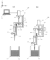
도 1은 본 개시에 관한, 분주 장치 구성과 액면 검지 동작의 일례를 나타내는 도면.
도 2는 본 개시에 관한, 피스톤을 토출 방향으로 동작시켜 액면을 검지했을 때의 압력 파형도.
도 3은 본 개시에 관한, 피스톤을 흡인 방향으로 동작시켜 액면을 검지했을 때의 압력 파형도.
도 4는 통상의 분주 방법의 처리 플로를 나타내는 도면.
도 5는 실시예 1에 관한, 액 중에서 공기를 미리 정해진 양 미량 토출했을 때의 압력 파형도.
도 6은 실시예 1에 관한, 액 중에서 액체를 미리 정해진 양 미량 흡인했을 때의 압력 파형도.
도 7은 실시예 2에 관한, 분주 처리 플로를 나타내는 도면.
도 8은 실시예 2에 관한, 액면 검지 파라미터를 임의로 설정하고, 피스톤을 토출 방향으로 동작시켜 액면을 검지했을 때의 압력 파형도.
도 9는 실시예 2에 관한, 액면 검지 파라미터를 임의로 설정하고, 피스톤을 흡인 방향으로 동작시켜 액면을 검지했을 때의 압력 파형도.
도 10은 실시예 3에 관한, 칩 용량을 초과하여 흡인했을 때의 압력 파형도.
도 11은 실시예 3에 관한, 분주 처리 플로를 나타내는 도면.1 is a diagram showing an example of a dispensing device configuration and a liquid level detection operation according to the present disclosure.
Fig. 2 is a pressure waveform diagram when a liquid level is detected by operating a piston in a discharge direction according to the present disclosure.
Fig. 3 is a pressure waveform diagram when the liquid level is detected by operating the piston in the suction direction according to the present disclosure.
Fig. 4 is a diagram showing a processing flow of a normal dispensing method;
Fig. 5 is a pressure waveform diagram when a predetermined amount of air is ejected from a liquid in Example 1;
Fig. 6 is a pressure waveform diagram when a predetermined amount of a small amount of liquid is sucked from the liquid in Example 1;
Fig. 7 is a diagram showing a dispensing processing flow according to Example 2;
Fig. 8 is a pressure waveform diagram when the liquid level is detected by operating the piston in the discharge direction with the liquid level detection parameters arbitrarily set according to Example 2;
Fig. 9 is a pressure waveform diagram when the liquid level is detected by operating the piston in the suction direction with the liquid level detection parameters arbitrarily set according to Example 2;
Fig. 10 is a pressure waveform diagram when suction exceeds the chip capacity in Example 3;
Fig. 11 is a diagram showing a dispensing processing flow according to Example 3;
이하, 도면을 참조하여 본 발명, 즉, 액체 시료를 분주 칩으로 흡인하고, 흡인한 액체 시료를 소정량 토출하여 분주를 행하는 분주 장치로서, 분주 장치의 내압을 측정하는 압력 센서를 구비하고, 압력 센서가 측정한 압력 파형으로부터 분주 칩의 종류를 판정하는 분주 장치, 또한 액체 시료를 분주 칩으로 흡인하고, 흡인한 액체 시료를 소정량 토출하여 분주를 행하는 분주 장치의 분주 방법으로서, 분주 장치의 내압을 측정하고, 측정한 압력 파형으로부터 분주 칩의 종류를 판정하는 분주 방법의 실시 형태에 대하여 설명한다.Hereinafter, the present invention with reference to the drawings, that is, a dispensing device for dispensing by sucking a liquid sample with a dispensing chip and dispensing a predetermined amount of the sucked liquid sample, comprising a pressure sensor for measuring internal pressure of the dispensing device, A dispensing device that determines the type of a dispensing chip from a pressure waveform measured by a sensor, and a dispensing method of a dispensing device that suctions a liquid sample with the dispensing chip and discharges a predetermined amount of the sucked liquid sample to perform dispensing, the internal pressure of the dispensing device An embodiment of a dispensing method for measuring and determining the type of dispensing chip from the measured pressure waveform will be described.
또한, 이하에 나타내는 도면은 본 발명에 따라 구체적인 실시 형태를 나타내고 있지만, 이들은 본 발명의 이해를 위한 것이며, 결코 본 발명을 한정적으로 해석하는 것은 아니다. 본 명세서에 있어서, 압력이란, 분석 장치의 배관의 내압을 의미하고, 장치에 탑재되는 압력 센서로 검출된다.In addition, although the drawing shown below shows specific embodiment according to this invention, these are for the understanding of this invention, and in no way interpret this invention limitedly. In this specification, pressure means the internal pressure of the piping of an analysis device, and is detected by the pressure sensor mounted in the device.
도 1은 본 개시에 관한, 압력식의 액면 검지를 행하는 분주 장치(100)를 나타내는 도면이다. 분주 장치(100)는, 전체 형상이 L형을 이루는 베이스(101)를 구비하고, 베이스(101)의 상부에는 구동부인 모터(102)가 마련되어 있다. 베이스(101)에는, 모터(102)의 회전축에 커플링(103)을 통해 접속된 사다리꼴 나사 또는 볼 나사 등으로 이루어지는 나사축(104)이 회전 가능하게 마련되어 있다.1 is a diagram showing a
나사축(104)에는, 나사축(104)을 통과하는 슬라이더(106)와, 나사축(104)에 대하여 나사 결합된 너트(105)가 마련되어 있다. 슬라이더(106)는 베이스(101)에 마련된 리니어 가이드(107)와 접속되어 있고, 너트(105)와 슬라이더(106)의 각각은, 도면에 나타내어진 화살표 S의 방향을 따라 상하 이동 가능하거나 또는 미끄럼 이동 가능하다. 또한, 슬라이더(106)는 하방으로 돌출되는 피스톤(108)과 접합하여, 회전하지 않고 상하 이동하도록 구성된다. 상술한 바와 같이, 피스톤(108)과, 피스톤 수용부(109)는 피펫 기구를 구성한다. 피스톤(108)을 동작시키면 시스템 관내의 압력이 변화하고, 피펫 기구는, 그 압력 변화를 측정하는 압력 센서(113)를 탑재하고 있다. 압력 센서(113)의 측정값은, 제어부인 제어용 컴퓨터(116)에 입력되어, 그 메모리에 순차적으로 기억된다.The
피펫 기구의 피스톤(108)의 상하 이동에 의해, 펌프의 역할을 한다. 피펫 기구의 피스톤 수용부(109)의 선단에는, 칩(110)이 장착되어 있다. 당해 칩(110)의 상방에는, 칩 분리부(111)가 마련되어 있다. 칩 분리부(111)는 U자형의 절결, 혹은 칩(110)의 개구부의 직경보다 작은 직경의 관통 구멍이 마련되어 있다. 칩 분리부(111)의 상단과 베이스(101)에 접속된 스프링 등의 스프링재(112)에 의해, 칩 분리부(111)는 상시 상방으로 가압되어 있음과 함께, 화살표 S를 따라 상하로 이동하도록 구성되어 있다. 또한 장치 내의 다양한 장소에 설치된 작은 용기에 분주하기 위해, 분주 장치(100)는 수평 방향 및 연직 방향으로 자유자재로 구동되는, 도시 생략한 자동 스테이지 상에 설치된다. 제어용 컴퓨터(116)는 구동부인 분주용 모터(102) 및 자동 스테이지 등을 제어한다.By the up and down movement of the
분주할 액체(114)와 해당 액체가 수용되어 있는 액체 수납부(115)가 있고, 분주할 액체(114)의 액면 높이 정보를 취득할 필요가 있다. 압력식의 액면 검지의 경우에는, 피스톤(108)을 흡인 또는 토출 방향으로 구동하여, 공기 흡인 또는 공기 토출하면서, 그때의 압력값을 압력 센서(113)로 측정한다. 공기 흡인 또는 공기 토출을 하면서, 자동 스테이지 등으로 분주 장치(100)의 전체를 연직 방향 하향으로 구동하여(도 1의 (a)), 분주할 액체(114)의 액면에 접촉하면(도 1의 (b)), 분주할 액체(114)를 미량 흡인 또는 미량 토출함으로써, 공기 흡인 또는 공기 토출 시의 압력값과의 변화가 일어나고, 이 압력값의 변화를 파악하여, 연직 방향의 자동 스테이지와 피스톤(108)은 정지하여, 액면을 검지한다.There is a
도 2는 토출 방식에 의한 액면 검지 시의 압력 파형 200의 일례이다. 토출 방식에서는, 피스톤(108)을 토출 방향으로 구동하면서, 자동 스테이지에 접속한 분주 장치(100)를 연직 하향 방향으로 구동시켰을 때의 압력을 압력 센서(113)로 측정하였다. 칩 선단이 액면에 접촉하면, 액체에 의해 선단부가 폐색되어, 토출된 공기에 의해 압력은 정압 측으로 상승한다. 압력 파형 201은 미량 분주용 칩을 사용했을 때의 파형이다. 압력 파형 202는 대용량 분주용 칩을 사용했을 때의 파형이다.2 is an example of a
피스톤 구동 속도 및 자동 스테이지의 구동 속도는 임의로 설정하는 것이 가능하지만, 여기서 나타내는 압력 파형 201, 202의 압력 파형은, 동일한 동작 파라미터에 의해 측정한 파형이다. 공기 토출 개시 전(203)은 대기압(204)의 압력이다.The piston drive speed and the drive speed of the automatic stage can be arbitrarily set, but the pressure waveforms of the
공기 토출(205)에 있어서 피스톤(108)은 토출 방향으로 동작하기 시작하고, 압력은 206으로 상승한다. 시간 207로부터 분주할 액체(114)에 접촉하기 시작하여, 시간 208 동안에 변화하는 압력값으로부터, 각각 근사 직선(209, 210)이 얻어진다. 이들 압력의 변화를 파악하는 것에 더하여, 사전의 실험으로부터 얻어져, 메모리에 기억되어 있는 압력 역치(211, 212)를 초과한 시간 213에 있어서, 제어용 컴퓨터(116)는 피스톤(108) 및 자동 스테이지를 정지하도록 제어한다. 이상의 동작으로 액면 높이 정보를 취득한다. 또한, 시간 213에 있어서, 각각 최대 압력 값(214, 215)이 측정되었다.In
도 3은 흡인 방식에 의한 액면 검지 시의 압력 파형 300의 일례이다. 피스톤(108)을 흡인 방향으로 구동하면서, 자동 스테이지에 접속한 분주 장치(100)를 연직 하향 방향으로 구동시켰을 때의 압력을 압력 센서(113)로 측정하였다. 공기 흡인 개시 전(301)은 대기압(302)의 압력으로 되어 있다. 공기 흡인(303)에 의해 압력(304)에 저하되고, 시간 305로부터 칩 선단이 분주 액체(114)에 접촉하기 시작하여, 액체를 칩 내부에 흡인하고 있다.3 is an example of a
압력 파형 306은 미량 분주용 칩을 사용했을 때의 파형이다. 압력 파형 307은 대용량 분주용 칩을 사용했을 때의 파형이다. 피스톤 구동 속도 및 자동 스테이지의 구동 속도는 임의로 설정하는 것이 가능하지만, 여기서 나타내는 압력 파형 306, 307의 압력 파형은, 동일한 동작 파라미터에 의해 측정한 파형이다.The
시간 308 동안에 변화하는 압력값으로부터, 각각 근사 직선(309, 310)이 얻어진다. 제어용 컴퓨터(116)는 압력 센서(113)의 측정값에 의해, 이들 압력의 변화를 파악하는 것에 더하여, 미리 검증으로부터 얻어져, 메모리에 기억되어 있는 압력 역치(311, 312)를 초과한 시간 313에 있어서, 피스톤(108) 및 자동 스테이지를 정지한다. 이상의 동작으로 액면 높이 정보를 취득한다. 또한, 313에 있어서 측정된 최저 압력값은 각각 314, 315이다.From the changing pressure values during
도 4는 통상의 분주 방법의 처리 플로 S400을 나타내는 도면이다. 이하에, 도 4를 참조하여, 분주 장치가 분주할 때의 동작 S401 내지 S410에 대하여 설명한다.Fig. 4 is a diagram showing a processing flow S400 of a normal dispensing method. Below, with reference to FIG. 4, operations S401 to S410 when the dispensing device performs dispensing will be described.
(S401)(S401)
압력 파형 데이터를 취득 개시하고, 액면 검지 판정 시에 기준이 되는 대기압(204) 및 대기압(302)을 측정하여, 제어용 컴퓨터(116)의 메모리 등에 기억한다.Acquisition of pressure waveform data is started, and
(S402)(S402)
액면 높이 정보 취득을 위해, 자동 스테이지를 구동하여 액면을 향하여 연직 하방으로 이동시킨다. 이때 피스톤(108)은 흡인 방향 혹은 토출 방향의 동작을 임의로 설정할 수 있다. 토출 방향으로 동작시켰을 때에는 압력 센서(113)로 압력값(206)이 측정되고, 흡인 방향으로 동작시켰을 때에는 압력값(304)이 측정된다.In order to obtain the liquid surface height information, the automatic stage is driven and moved vertically downward toward the liquid surface. At this time, the operation of the
(S403)(S403)
액면 접촉(207, 305)에 있어서 칩 선단이 액면에 도달, 접촉한다.In the liquid surface contact (207, 305), the tip of the chip reaches and contacts the liquid surface.
(S404)(S404)
토출 방향으로 동작시켰을 때에는 액면 접촉(207)으로부터 변화하는 압력에 의해 근사 직선(209 혹은 210)을 얻는다. 흡인 방향으로 동작시켰을 때에는 액면 접촉 시간 305로부터 변화하는 압력에 의해 근사 직선(309 혹은 310)을 얻는다. 액면을 검지하여 피스톤(108) 및 자동 스테이지가 정지하는 조건은, 사전의 실험으로부터 얻어진 압력 역치를 초과하는 것 및 근사 직선의 기울기가 일정 값 이상으로 되어 있는 것이다.When operated in the discharge direction, an approximate
(S405)(S405)
정지한 연직 방향의 위치를 메모리에 기억한다.The stopped position in the vertical direction is stored in memory.
(S406)(S406)
피스톤(108)을 토출 방향 동작에서 액면을 검지한 경우에는, 분주할 액체(114)의 액면으로부터 연직 상방으로 이탈한 위치에서, 소정량 흡인 개시 위치로 피스톤을 이동시킨다. 피스톤(108)을 흡인 방향 동작에서 액면을 검지한 경우에는, 분주할 액체(114)의 액면으로부터 연직 상방으로 이탈한 위치에서 액면 돌입 시간 308의 구간에 미량 흡인한 액체를 토출한다. 그 후 피스톤(108)을 소정의 흡인 개시 위치로 이동시킨다.When the
(S407)(S407)
설정한 소정량을 흡인한다.The set predetermined amount is suctioned.
(S408)(S408)
분주 장치(100)가 설치된 자동 스테이지에 의해, 연직 수평으로 분주 장치(100)를 구동하여, 소정의 토출 위치로 이동시킨다.The automatic stage on which the
(S409)(S409)
소정량을 토출한다.Discharge a predetermined amount.
또한, 상술한 토출 방식은, 검지 시에 시료를 흡인하지 않기 때문에 칩 내에 잉여액 잔여물이 없다. 또한, 흡인 방식에서는, 흡인 시, 칩이 막히는 원인이 되는 응고 유무 등을, 분주 본 흡인 개시 전에 검지할 수 있을 가능성이 있다.Further, in the discharge method described above, since the sample is not sucked at the time of detection, there is no surplus liquid residue in the chip. Further, in the suction method, there is a possibility that the presence or absence of coagulation, etc., which causes the chip to clog during suction, can be detected prior to the start of suction main dispensing.
실시예 1Example 1
본 실시예는, 액체에 칩 선단이 미리 접촉한 상태에서, 공기의 미량 토출 혹은 미량 흡인을 함으로써 얻어지는 압력 변화의 근사 직선으로부터 칩 종류의 판정을 행하는 분주 장치 및 방법의 실시예이다. 도 5와 도 6을 사용하여, 본 실시예의 칩 판정 방법에 대하여 설명한다.This embodiment is an embodiment of a dispensing device and method for determining the type of chip from an approximate straight line of pressure change obtained by ejecting or sucking a small amount of air in a state where the tip of the chip is in contact with liquid in advance. The chip determination method of this embodiment will be described using FIGS. 5 and 6 .
도 5는 액체에 대하여 공기를 미량 토출했을 때의 압력 파형 500의 일례를 나타낸다. 압력 파형 501은 미량 분주용 칩을 사용했을 때의 파형이다. 압력 파형 502는 대용량 분주용 칩을 사용했을 때의 파형이다. 칩 선단이 액체에 접촉하고 있는 상태에서, 압력 센서로 압력값(504)을 측정하고 있다. 시간 503 내지 시간 505 동안, 공기를 미량 토출하면 피스톤 정지 시간 506에 있어서 각각 압력값(508, 507)이 측정된다.5 shows an example of a
시간 505 동안에 얻어진 압력 변화로부터 근사 직선(509 및 510)을 얻는다. 동 도면에 명백한 바와 같이, 이들 근사 직선은 칩 종류마다 특징을 갖기 때문에, 정지 시의 압력값 또는 근사 직선의 기울기를 미리 측정한 값과 비교함으로써 칩 종류의 판정이 가능하다.Approximate
도 6은 액체를 미량 흡인했을 때의 압력 변화 파형 600의 일례이다. 압력 파형 601은 미량 분주용 칩을 사용했을 때의 파형이다. 압력 파형 602는 대용량 분주용 칩을 사용했을 때의 파형이다. 칩 선단이 액체에 접촉하고 있는 상태에서, 압력 센서로 압력값(603)을 측정하고 있다. 시간 604 내지 시간 605 동안, 액체를 미량 흡인하면 피스톤 정지 시간 606에 있어서 각각 압력값(608, 607)이 측정된다.Fig. 6 is an example of a
시간 605 동안에 얻어진 압력 변화로부터 근사 직선(609 및 610)을 얻는다. 이들 근사 직선은 칩 종류마다 특징을 갖기 때문에, 정지 시의 압력값이나 근사 직선의 기울기를 미리 측정한 값과 비교함으로써 판정이 가능하다.Approximate
본 실시예의 분주 장치, 압력 파형을 이용한 액면 검지 방법 및 칩 종류 판정 방법에 의하면, 압력 파형의 특징의 차이, 흡인 중의 압력 파형과 흡인 시간의 관계성 등으로부터, 사용하고 있는 칩 종류의 판정이 가능하게 된다.According to the dispensing device of the present embodiment, the liquid level detection method using pressure waveform, and the chip type determination method, the type of chip being used can be determined based on the difference in characteristics of the pressure waveform, the relationship between the pressure waveform during suction and the suction time, and the like. will do
실시예 2Example 2
실시예 2는, 액면 검지 시에 얻어지는 압력 파형을 이용한 칩 종류 판정 방법이다. 도 3, 도 7의 액면 검지를 이용한 칩 종류 판정 플로 S700의 S701 내지 S712, 도 8, 도 9를 사용하여 설명한다. 또한, 이 칩 종류 판정 플로 S700의 동작 처리 주체는, 제어부인 제어용 컴퓨터(116) 등이다.Embodiment 2 is a chip type determination method using a pressure waveform obtained at the time of liquid level detection. Description will be made using S701 to S712 of FIGS. 3 and 7 and FIGS. 8 and 9 of the chip type determination flow S700 using liquid surface detection. In addition, the main body of operation and processing of this chip type determination flow S700 is the
(S701)(S701)
압력 파형 데이터를 취득 개시하고, 액면 검지 판정 시에 기준이 되는 대기압(204) 및 대기압(302)을 압력 센서(113)로 측정하여, 기억한다.Acquisition of pressure waveform data is started, and
(S702)(S702)
액면 높이 정보 취득을 위해, 자동 스테이지를 구동하여 액면을 향하여 연직 하방으로 이동시킨다. 이때 피스톤(108)은 흡인 방향 혹은 토출 방향의 동작을 임의로 설정할 수 있다. 토출 방향으로 동작시켰을 때에는 압력 센서(113)로 압력값(206)이 측정되고, 흡인 방향으로 동작시켰을 때에는 압력값(304)이 측정된다.In order to obtain the liquid surface height information, the automatic stage is driven and moved vertically downward toward the liquid surface. At this time, the operation of the
(S703)(S703)
액면 접촉(207, 305)에 있어서 칩 선단이 액면에 도달, 접촉한다.In the liquid surface contact (207, 305), the tip of the chip reaches and contacts the liquid surface.
(S704)(S704)
액면 검지 시, 피스톤 및 자동 스테이지의 정지 조건은, 미리 기억된 압력 역치를 초과하는 것 및 근사 직선의 기울기가 일정 값 이상으로 되어 있는 것이다.At the time of detecting the liquid level, the stopping conditions of the piston and the automatic stage are that the pre-stored pressure threshold is exceeded and the slope of the approximate straight line is at least a certain value.
토출 방향으로 동작시켜 대용량 분주용 칩을 사용한 경우, 시간 213에 있어서 피스톤이 정지하여 압력 파형 202로부터 근사 직선(210)을 얻는다. 액면 검지 동작에 관한 압력 역치와 근사 직선의 기울기 조건을, 대용량 분주용 칩의 파라미터로 설정하고 있는 경우를 생각한다. 이 상태에서 미량 분주용 칩을 사용하면, 설정 압력 역치 및 기울기 조건이 미량 분주용 칩의 조건보다 작게 설정되어 있기 때문에, 액면을 검지하여 정지할 때까지의 시간이 짧아진다. 그 때문에, 미량 분주용 칩의 압력 파형은 801에 나타내는 형상으로 된다. 시간 802에 있어서 피스톤이 정지하여 근사 직선(803)을 얻는다.When a chip for dispensing a large capacity is used by operating in the discharge direction, the piston stops at
흡인 방향으로 동작시킨 경우, 대용량 분주용 칩은 시간 313에 있어서 피스톤이 정지하여 압력 파형 307로부터 근사 직선(310)을 얻는다. 이쪽도 마찬가지로, 액면 검지 동작에 관한 압력 역치와 근사 직선의 기울기 조건을, 대용량 분주용 칩의 파라미터로 설정하고 있는 경우를 생각한다. 이 상태에서 미량 분주용 칩을 사용하면, 미량 분주용 칩의 조건보다 설정 압력 역치는 크고, 기울기 조건은 작게 설정되어 있기 때문에, 액면을 검지하여 정지할 때까지의 시간이 짧아진다.In the case of operation in the suction direction, the piston stops at
그 때문에, 미량 분주용 칩의 압력 파형은 901에 나타내는 형상으로 된다. 시간 902에 있어서 피스톤이 정지하여 근사 직선(903)을 얻는다.Therefore, the pressure waveform of the micro-amount dispensing chip has a shape shown at 901. At
(S705)(S705)
S701 내지 S704의 액면 검지 과정에서 취득한 압력 파형을 이용한다. 피스톤을 토출 방향으로 동작시켜 액면 검지를 행한 경우에는, 근사 직선(210 및 803)으로부터 칩 종류의 판정을 한다. 피스톤을 흡인 방향으로 동작시켜 액면 검지를 행한 경우에는 근사 직선(310 및 903)으로부터 칩 종류의 판정을 한다.The pressure waveform acquired in the liquid level detection process of S701 to S704 is used. When liquid level detection is performed by operating the piston in the discharge direction, the type of chip is determined from approximate
여기서, 피스톤을 흡인 방향으로 동작시킨 액면 검지를 예로 들어 압력 센서(113)로 측정되는 압력 P에 대하여 고찰한다. 압력 ΔP=2×σ/(D/2)라고 생각된다. σ는 액체의 표면 장력이며, D는 칩 선단 내경을 나타낸다. 이 식으로부터 흡인 압력값은 흡인 액체의 표면 장력 σ 및 칩 선단 내경 D를 파라미터로 갖는 것을 알 수 있다.Here, the pressure P measured by the
예로 든 미량 분주용 칩과 대용량 분주용 칩에서는, 미량 분주용 칩 쪽이 선단 내경이 작기 때문에, 도 3에 나타내는 시간 313으로부터도 단위 시간당 압력 변화가 큰 것을 알 수 있다. 동일한 액체를 흡인했을 때, 칩 선단이 작은 칩 쪽이 압력 변화 즉, 근사 직선의 기울기가 커지는 것을 알 수 있다. 이로부터, 칩 선단 직경이 상이한 칩은 얻어지는 근사 직선의 기울기에 각각 상이한 특징량을 갖는 것을 말할 수 있다.In the examples of the micro-amount dispensing chip and the large-capacity dispensing chip, since the micro-amount dispensing chip has a smaller tip end inner diameter, it can be seen from the
또한, 칩은 분주 용량에 따라 칩 내의 공기 용량이 다르다. 일반적으로 분주 용량이 많은 칩은 보다 많은 액체를 흡인하기 위해 내부의 공기 용량이 많다. 압축성 유체인 공기가 많으면, 압력 센서가 검지하는 값에 지연이 발생하기 때문에, 칩 용량이 보다 작은 쪽이 단위 시간당 근사 직선의 기울기는 커진다. 즉 칩 선단 직경이 동등한 경우에도 근사 직선의 기울기는, 각각 상이한 특징을 갖는 것을 알 수 있다.In addition, the amount of air in the chip is different according to the dispensing capacity of the chip. In general, a chip with a large dispensing capacity has a large internal air capacity to suck more liquid. If there is a large amount of air, which is a compressive fluid, there is a delay in the value detected by the pressure sensor, so the slope of the approximate straight line per unit time increases when the chip capacity is smaller. In other words, even when the tip diameters of the chips are the same, it can be seen that the slopes of the approximate straight lines have different characteristics.
이들 특징을 이용하여, 미리 검증 결과로부터 얻은 압력 파형과 비교함으로써 적절한 칩을 사용하고 있는지 판정을 행한다.Using these characteristics, it is determined whether an appropriate chip is being used by comparing with the pressure waveform obtained from the verification result in advance.
(S706)(S706)
분주에 부적절한 칩이 장착되어 있는 것으로 하여 에러를 통지한다. 분주량에 대하여 충분한 용량을 가진 칩이 장착되어 있는 경우, 분주 자체는 가능하다. 그러나, 칩 내부의 공기 용량이 많기 때문에 소요되는 분주 정밀도를 만족시킬 수 없을 가능성이 있다. 여기서 장착 칩의 에러를 검출함으로써, 사양의 분주 정밀도를 담보하는 것이 가능하다.An error is reported assuming that a chip inappropriate for dispensing is installed. The dispensing itself is possible if a chip having sufficient capacity for the dispensing amount is mounted. However, since the air capacity inside the chip is large, there is a possibility that the required dispensing accuracy cannot be satisfied. By detecting the error of the mounted chip here, it is possible to ensure the frequency division accuracy of the specifications.
(S707)(S707)
정지한 연직 방향의 위치를 기억한다.It stores the position in the vertical direction at which it stopped.
(S708)(S708)
피스톤(108)을 토출 방향 동작에서 액면을 검지한 경우에는, 분주할 액체(114)의 액면으로부터 연직 상방으로 이탈한 위치에서, 소정량 흡인 개시 위치로 피스톤을 이동시킨다. 피스톤(108)을 흡인 방향 동작에서 액면을 검지한 경우에는, 분주할 액체(114)의 액면으로부터 연직 상방으로 이탈한 위치에서 액면 돌입 시간 308의 구간에 미량 흡인한 액체를 토출한다. 그 후 피스톤(108)을 소정의 흡인 개시 위치로 이동시킨다.When the
(S709)(S709)
설정한 소정량을 흡인한다.The set predetermined amount is suctioned.
(S710)(S710)
분주 장치(100)가 설치된 자동 스테이지에 의해, 연직 수평으로 분주 장치(100)를 구동하여, 소정의 토출 위치로 이동시킨다.The automatic stage on which the
(S711)(S711)
소정량을 토출한다.Discharge a predetermined amount.
본 실시예에 의하면, 액면 검지 시에 얻어지는 압력 파형을 이용한 칩 종류 판정을 행할 수 있다.According to this embodiment, the chip type can be determined using the pressure waveform obtained at the time of liquid level detection.
실시예 3Example 3
실시예 1, 2는 칩 용량이나 칩 선단 직경에 크게 차가 있는 경우에 있어서 유효한 판정 방법이다. 예를 들어, 분주 용량 10 마이크로리터와 20 마이크로리터의 칩에서는, 용량, 선단 직경 모두 차가 작기 때문에 실시예 1, 2로 판정할 수 없는 경우가 있다. 그러한 경우에 본 실시예에 나타내는 방법을 사용하여 칩의 종류를 판정한다.Embodiments 1 and 2 are effective judgment methods when there is a large difference in chip capacitance or chip tip diameter. For example, in the case of chips with dispensing capacities of 10 microliters and 20 microliters, the difference in both the capacities and the tip diameters is small, so there are cases in which it cannot be judged in Example 1 or 2. In such a case, the type of chip is determined using the method shown in this embodiment.
도 10 및 도 11을 사용하여, 본 실시예의 칩 종류 판정에 대하여 설명한다. 여기서는, 시판중인 필터를 구비하는 1회용 칩을 사용한 경우를 전제로 생각한다.Chip type determination in this embodiment will be described using FIGS. 10 and 11 . Here, it is assumed that a disposable chip equipped with a commercially available filter is used.
도 10은 액체를 흡인했을 때의 압력 파형 1000의 예이다. 압력 파형 1001은 칩 용량을 초과하여 과잉으로 액체를 흡인한 경우의 압력 파형이다. 흡인 전 시간 1002에서는, 미리 기억되어 있는 액면 높이로 자동 스테이지를 연직 하향 방향으로 이동시킨다. 흡인 시간 1003에서 액체를 흡인하고 있고, 과잉 흡인 시간 1004에서 흡인 액체가 필터 부분으로 침입하여 압력이 저하되고 있다. 또한, 동 도면의 점선 1005는 정상 압력 파형을 나타내고 있다.10 is an example of a
도 11은 본 실시예의 동작 플로 S1100이다. 이하에 플로 S1101 내지 S1108을 사용하여 칩 종류 판정 방법을 설명한다.11 is an operation flow S1100 of this embodiment. The chip type determination method will be described below using flows S1101 to S1108.
(S1101)(S1101)
압력 파형 데이터를 취득 개시하고, 기준이 되는 대기압을 측정하여 기억한다.Acquisition of pressure waveform data is started, atmospheric pressure serving as a standard is measured and stored.
(S1102)(S1102)
분주 장치(100)가 접속되어 있는 자동 스테이지를 연직 하향 방향으로, 미리 기억되어 있는 흡인 가능한 액면 높이까지 이동시켜, 액체의 흡인을 개시한다.The automatic stage to which the
(S1103) 흡인 압력 파형 칩 종류를 판정(S1103) Determination of suction pressure waveform chip type
S1101로부터 계속하여 취득하고 있는 흡인 압력 파형의 변화로부터 판정한다. 흡인에서의 동작 파라미터는, 각종 액체의 액체 물리 정수(점도, 표면 장력, 비중, 접촉각)나 분주량에 기초하여, 분주 시험 등에 의해 검증된 값으로 설정된다. 그 때문에, 어느 임의의 시점에서의 흡인량을 산출하는 것은 가능하다.It is determined from the change in the suction pressure waveform continuously acquired from S1101. Operational parameters in suction are set to values verified by a dispensing test or the like based on liquid physical constants (viscosity, surface tension, specific gravity, contact angle) of various liquids or dispensing amounts. Therefore, it is possible to calculate the suction amount at any arbitrary time point.
즉, 흡인에서의 동작 파라미터로부터, 칩마다 어느 타이밍에 용량을 초과해 버릴지 예측할 수 있다. 정상적으로 흡인이 행해지고 있는 경우, 흡인 압력은 어느 일정 압력으로 안정적으로 추이해 가고, 흡인이 정지했을 때 정압 측으로 되돌아간다. 칩 용량을 초과하여 필터에 액체가 도달했을 때 흡인 압력이 저하된다.That is, it is possible to predict at what timing the capacity will be exceeded for each chip from the operating parameters in suction. When suction is normally performed, the suction pressure stably transitions to a certain constant pressure, and returns to the positive pressure side when suction is stopped. When liquid exceeds the chip capacity and reaches the filter, the suction pressure drops.
예를 들어, 분주 용량 10 마이크로리터와 20 마이크로리터 2종류의 칩을 사용하고 있는 경우를 생각한다. 20 마이크로리터의 분주 동작을, 용량 10 마이크로리터의 칩으로 행한 경우, 어느 특정 시간에 칩 용량을 초과해 버린다. 어느 특정 시간에 흡인 압력이 저하되어 있는 경우, 칩 용량을 초과하여 과잉으로 흡인하고 있다고 판단할 수 있기 때문에 칩 종류의 판정이 가능하다.For example, consider a case in which two types of chips are used with dispensing capacities of 10 microliters and 20 microliters. When a dispensing operation of 20 microliters is performed with a chip having a capacity of 10 microliters, the capacity of the chip is exceeded at a certain time. When the suction pressure is lowered for a certain period of time, it can be judged that the suction exceeds the chip capacity and is excessively suctioned, so the type of chip can be determined.
(S1104)(S1104)
흡인 동작을 정지하여, 칩 종류의 판정을 행한다.The suction operation is stopped, and the chip type is determined.
(S1105)(S1105)
판정 결과에 기초하여, 분주에 부적절한 칩이 장착되어 있는 것으로 하여 에러를 통지한다.Based on the determination result, an error is notified assuming that a chip inappropriate for dispensing is mounted.
(S1106)(S1106)
흡인 동작을 완료한다.Complete the suction action.
(S1107)(S1107)
분주 장치(100)가 설치된 자동 스테이지에 의해, 연직 수평으로 분주 장치(100)를 구동하여, 소정의 토출 위치로 이동시킨다.The automatic stage on which the
(S1108)(S1108)
소정량을 토출한다.Discharge a predetermined amount.
본 실시예에 의하면, 분주 용량이 작은 칩의 종류를 판정할 수 있다.According to this embodiment, it is possible to determine the type of chip having a small dispensing capacity.
본 발명은 상기한 실시예에 한정되는 것은 아니며, 다양한 변형예가 포함된다. 예를 들어, 상기한 실시예는 본 발명의 보다 나은 이해를 위해 상세하게 설명한 것이며, 반드시 설명의 모든 구성을 구비하는 것으로 한정되는 것은 아니다.The present invention is not limited to the above embodiment, and various modified examples are included. For example, the above embodiments have been described in detail for a better understanding of the present invention, and are not necessarily limited to having all the configurations of the description.
또한, 상술한 각 구성, 기능, 제어 컴퓨터 등은, 그것들의 일부 또는 전부를 실현하는 프로그램을 작성하는 예를 중심으로 설명했지만, 그것들의 일부 또는 전부를 예를 들어 집적 회로로 설계하는 등에 의해 하드웨어로 실현해도 된다는 것은 말할 것도 없다. 즉, 처리부의 전부 또는 일부의 기능은, 프로그램 대신에, 예를 들어 ASIC(Application Specific Integrated Circuit), FPGA(Field Programmable Gate Array) 등의 집적 회로 등에 의해 실현해도 된다.Incidentally, each configuration, function, control computer, etc. described above has been explained mainly with an example of creating a program realizing some or all of them, but by designing some or all of them as an integrated circuit, for example, hardware It goes without saying that it can be realized with That is, the functions of all or part of the processing unit may be realized by, for example, an integrated circuit such as an Application Specific Integrated Circuit (ASIC) or Field Programmable Gate Array (FPGA) instead of a program.
100: 분주 장치
101: 베이스
102: 모터
103: 커플링
104: 나사축
105: 너트
106: 슬라이더
107: 리니어 가이드
108: 피스톤
109: 피스톤 수용부
110: 디스포저블 칩
111: 칩 분리부
112: 스프링재
113: 압력 센서
114: 분주할 액체
115: 액체 수납부
116: 제어용 컴퓨터100: dispensing device
101: base
102: motor
103: coupling
104: screw shaft
105: nut
106: slider
107: linear guide
108: piston
109: piston receiving portion
110: Disposable chip
111: chip separator
112: spring material
113: pressure sensor
114: liquid to be dispensed
115: liquid storage unit
116: control computer
Claims (15)
상기 분주 장치의 내압을 측정하는 압력 센서를 구비하고, 상기 압력 센서가 측정한 압력 파형으로부터 상기 분주 칩의 종류를 판정하는,
것을 특징으로 하는 분주 장치.A dispensing device for dispensing by suctioning a liquid sample with a dispensing chip and dispensing a predetermined amount of the sucked liquid sample, comprising:
Equipped with a pressure sensor for measuring the internal pressure of the dispensing device, and determining the type of the dispensing chip from the pressure waveform measured by the pressure sensor,
Dispensing device characterized in that.
상기 압력 파형으로서, 액면 검지 시의 압력 파형을 이용하여, 상기 분주 칩의 종류를 판정하는,
것을 특징으로 하는 분주 장치.According to claim 1,
determining the type of the dispensing chip using, as the pressure waveform, a pressure waveform at the time of liquid level detection;
Dispensing device characterized in that.
흡인 및 토출을 행하는 피펫 기구와, 상기 피펫 기구를 구동하는 구동부를 구비하고,
상기 피펫 기구에 상기 분주 칩을 설치하고, 상기 구동부는, 상기 피펫 기구를 흡인 혹은 토출 방향으로 구동하는,
것을 특징으로 하는 분주 장치.According to claim 2,
a pipette mechanism for suctioning and discharging, and a driving unit for driving the pipette mechanism;
The dispensing chip is installed in the pipette mechanism, and the drive unit drives the pipette mechanism in a suction or discharge direction.
Dispensing device characterized in that.
상기 압력 센서의 출력에 기초하여, 상기 구동부를 제어하는 제어부를 구비하는,
것을 특징으로 하는 분주 장치.According to claim 3,
Based on the output of the pressure sensor, having a control unit for controlling the driving unit,
Dispensing device characterized in that.
상기 제어부는, 상기 분주 칩의 액면 도달을 검출했을 때, 상기 구동부를 정지하여, 상기 분주 칩의 종류를 판정하는,
것을 특징으로 하는 분주 장치.According to claim 4,
When the control unit detects that the dispensing chip has reached the liquid level, stopping the driving unit to determine the type of the dispensing chip;
Dispensing device characterized in that.
상기 제어부는, 상기 분주 칩의 종류의 판정의 결과, 부적절한 분주 칩이 장착되어 있다고 판정한 경우, 에러 통지를 출력하는,
것을 특징으로 하는 분주 장치.According to claim 5,
The controller outputs an error notification when it is determined that an inappropriate dividing chip is mounted as a result of the determination of the type of the dividing chip.
Dispensing device characterized in that.
상기 제어부는, 상기 분주 칩의 종류의 판정의 결과, 적절한 분주 칩이 장착되어 있다고 판정한 경우, 액면 위치를 기억하는,
것을 특징으로 하는 분주 장치.According to claim 5,
The control unit, as a result of determining the type of the dispensing chip, stores the liquid level position when it is determined that an appropriate dispensing chip is mounted.
Dispensing device characterized in that.
상기 분주 칩으로서 필터를 구비하는 분주 칩을 사용하고,
당해 필터를 구비하는 분주 칩의 사양 용량을 초과하여 액체를 흡인한 경우에, 상기 압력 파형으로부터 상기 분주 칩의 종류를 판정하는,
것을 특징으로 하는 분주 장치.According to claim 1,
As the dispensing chip, a dispensing chip having a filter is used,
determining the type of the dispensing chip from the pressure waveform when the liquid is sucked in excess of the specified capacity of the dispensing chip equipped with the filter;
Dispensing device characterized in that.
상기 분주 장치의 내압을 측정하고, 측정한 압력 파형으로부터 상기 분주 칩의 종류를 판정하는,
것을 특징으로 하는 분주 방법.A dispensing method of a dispensing device for dispensing by suctioning a liquid sample with a dispensing chip and dispensing a predetermined amount of the sucked liquid sample, comprising:
Measuring the internal pressure of the dispensing device and determining the type of the dispensing chip from the measured pressure waveform;
Dispensing method characterized in that.
상기 압력 파형으로서, 액면 검지 시의 압력 파형을 이용하여, 상기 분주 칩의 종류를 판정하는,
것을 특징으로 하는 분주 방법.According to claim 9,
determining the type of the dispensing chip using, as the pressure waveform, a pressure waveform at the time of liquid level detection;
Dispensing method characterized in that.
상기 분주 칩을 흡인 혹은 토출 방향으로 구동하는,
것을 특징으로 하는 분주 방법.According to claim 10,
Driving the dispensing chip in the suction or discharge direction,
Dispensing method characterized in that.
상기 분주 칩의 액면 도달을 검출했을 때, 상기 구동을 정지하여, 상기 분주 칩의 종류를 판정하는,
것을 특징으로 하는 분주 방법.According to claim 11,
stopping the driving when detecting that the dispensing chip reaches the liquid level, and determining the type of the dispensing chip;
Dispensing method characterized in that.
상기 분주 칩의 종류의 판정의 결과, 부적절한 분주 칩이 장착되어 있다고 판정한 경우, 에러 통지를 출력하는,
것을 특징으로 하는 분주 방법.According to claim 12,
As a result of the determination of the type of the dividing chip, when it is determined that an inappropriate dividing chip is mounted, an error notification is output.
Dispensing method characterized in that.
상기 분주 칩의 종류의 판정의 결과, 적절한 분주 칩이 장착되어 있다고 판정한 경우, 액면 위치를 기억하는,
것을 특징으로 하는 분주 방법.According to claim 12,
As a result of the determination of the type of the dispensing chip, when it is determined that an appropriate dispensing chip is mounted, the position of the liquid level is stored.
Dispensing method characterized in that.
상기 분주 칩으로서 필터를 구비하는 분주 칩을 사용하고,
당해 필터를 구비하는 분주 칩의 사양 용량을 초과하여 액체를 흡인한 경우에, 상기 압력 파형으로부터 상기 분주 칩의 종류를 판정하는,
것을 특징으로 하는 분주 방법.According to claim 9,
As the dispensing chip, a dispensing chip having a filter is used,
determining the type of the dispensing chip from the pressure waveform when the liquid is sucked in excess of the specified capacity of the dispensing chip equipped with the filter;
Dispensing method characterized in that.
Applications Claiming Priority (1)
| Application Number | Priority Date | Filing Date | Title |
|---|---|---|---|
| PCT/JP2020/029640 WO2022029826A1 (en) | 2020-08-03 | 2020-08-03 | Dispensing device and method |
Publications (1)
| Publication Number | Publication Date |
|---|---|
| KR20230034352A true KR20230034352A (en) | 2023-03-09 |
Family
ID=80117179
Family Applications (1)
| Application Number | Title | Priority Date | Filing Date |
|---|---|---|---|
| KR1020237003741A KR20230034352A (en) | 2020-08-03 | 2020-08-03 | Dispensing device and method |
Country Status (6)
| Country | Link |
|---|---|
| US (1) | US20230314455A1 (en) |
| EP (1) | EP4190449A4 (en) |
| JP (1) | JPWO2022029826A1 (en) |
| KR (1) | KR20230034352A (en) |
| CN (1) | CN116194217A (en) |
| WO (1) | WO2022029826A1 (en) |
Citations (1)
| Publication number | Priority date | Publication date | Assignee | Title |
|---|---|---|---|---|
| JP2010256200A (en) | 2009-04-27 | 2010-11-11 | Aloka Co Ltd | Dispensing system |
Family Cites Families (10)
| Publication number | Priority date | Publication date | Assignee | Title |
|---|---|---|---|---|
| US4846003A (en) * | 1988-06-08 | 1989-07-11 | Beckman Instruments, Inc. | Acoustic impedance system for pipette tip detection |
| FI90207C (en) * | 1992-05-04 | 1994-01-10 | Wallac Oy | pipette |
| US5537880A (en) * | 1995-06-07 | 1996-07-23 | Abbott Laboratories | Automatic pipetting apparatus with leak detection and method of detecting a leak |
| JP3158084B2 (en) * | 1997-09-25 | 2001-04-23 | アロカ株式会社 | Analytical device with automatic dispensing function |
| JP4345619B2 (en) * | 2004-09-07 | 2009-10-14 | 日立工機株式会社 | Automatic dispensing device |
| JP2006194689A (en) * | 2005-01-12 | 2006-07-27 | Olympus Corp | Dispensing device, liquid level detection method, and cultivation treatment apparatus |
| US8307722B2 (en) * | 2005-05-19 | 2012-11-13 | Universal Bio Research Co., Ltd. | Method of detecting dispensed quantity, and liquid suction monitoring dispensing apparatus |
| EP2009449A1 (en) * | 2007-06-06 | 2008-12-31 | Hamilton Bonaduz AG | Method of controlling a pipetting process |
| JP5984584B2 (en) * | 2012-08-28 | 2016-09-06 | 株式会社日立ハイテクノロジーズ | Automatic analyzer |
| EP4030170B1 (en) * | 2018-12-18 | 2023-03-01 | Tecan Trading AG | Classifying liquid handling procedures with a neural network |
-
2020
- 2020-08-03 CN CN202080104323.9A patent/CN116194217A/en active Pending
- 2020-08-03 KR KR1020237003741A patent/KR20230034352A/en unknown
- 2020-08-03 JP JP2022541329A patent/JPWO2022029826A1/ja active Pending
- 2020-08-03 WO PCT/JP2020/029640 patent/WO2022029826A1/en active Application Filing
- 2020-08-03 EP EP20948592.9A patent/EP4190449A4/en active Pending
- 2020-08-03 US US18/013,933 patent/US20230314455A1/en active Pending
Patent Citations (1)
| Publication number | Priority date | Publication date | Assignee | Title |
|---|---|---|---|---|
| JP2010256200A (en) | 2009-04-27 | 2010-11-11 | Aloka Co Ltd | Dispensing system |
Also Published As
| Publication number | Publication date |
|---|---|
| US20230314455A1 (en) | 2023-10-05 |
| WO2022029826A1 (en) | 2022-02-10 |
| CN116194217A (en) | 2023-05-30 |
| JPWO2022029826A1 (en) | 2022-02-10 |
| EP4190449A4 (en) | 2024-03-20 |
| EP4190449A1 (en) | 2023-06-07 |
Similar Documents
| Publication | Publication Date | Title |
|---|---|---|
| JP5122949B2 (en) | Dispensing amount detection method and liquid absorption monitor type dispensing device | |
| JP5865633B2 (en) | Automatic analyzer | |
| JP5899075B2 (en) | Automatic analyzer | |
| JP5686744B2 (en) | Automatic analyzer | |
| JP6649942B2 (en) | Automatic analyzer | |
| WO2007076293A2 (en) | Method for ascertaining interferants in small liquid samples in an automated clinical analyzer | |
| WO2017033910A1 (en) | Automatic analysis device, dispensing method, and liquid surface detection method | |
| US20220128520A1 (en) | Autosampler for chromatograph and fluid chromatography system | |
| JP2004271266A (en) | Dispensing device and autoanalyzer using the same | |
| WO2018055929A1 (en) | Automatic analysis device | |
| JP6919535B2 (en) | Dispenser | |
| JP3907819B2 (en) | Liquid level detector | |
| KR20230034352A (en) | Dispensing device and method | |
| JP2010096643A (en) | Dispenser, specimen processor using the same, and automatic analyzer | |
| JP2015031586A (en) | Analyzer and liquid suction device | |
| JP7105577B2 (en) | automatic analyzer | |
| JPH02243960A (en) | System for operating dispenser of analysis apparatus | |
| WO2023132156A1 (en) | Automated analyzing device, and dispensing method | |
| JPWO2020085055A1 (en) | Automatic analyzer | |
| US20230236056A1 (en) | Dispensing device, automated analysis device, and dispensing method | |
| JP4363964B2 (en) | Dispensing device | |
| US20220276278A1 (en) | Liquid Dispensing Device | |
| JP2016040535A (en) | Automatic analyzer and method for controlling automatic analyzer | |
| CN116324422A (en) | Multi-point filtering liquid level detection method and device |