EP1745851A1 - Process, device and computerprogramm product for the classification of a liquid - Google Patents
Process, device and computerprogramm product for the classification of a liquid Download PDFInfo
- Publication number
- EP1745851A1 EP1745851A1 EP06116504A EP06116504A EP1745851A1 EP 1745851 A1 EP1745851 A1 EP 1745851A1 EP 06116504 A EP06116504 A EP 06116504A EP 06116504 A EP06116504 A EP 06116504A EP 1745851 A1 EP1745851 A1 EP 1745851A1
- Authority
- EP
- European Patent Office
- Prior art keywords
- liquid
- pressure
- fluid
- curve
- space
- Prior art date
- Legal status (The legal status is an assumption and is not a legal conclusion. Google has not performed a legal analysis and makes no representation as to the accuracy of the status listed.)
- Granted
Links
- 239000007788 liquid Substances 0.000 title claims abstract description 199
- 238000000034 method Methods 0.000 title claims abstract description 56
- 230000008569 process Effects 0.000 title abstract description 7
- 239000012530 fluid Substances 0.000 claims abstract description 122
- 238000005259 measurement Methods 0.000 claims description 10
- 238000004590 computer program Methods 0.000 claims description 8
- 239000012528 membrane Substances 0.000 claims description 8
- 239000000919 ceramic Substances 0.000 claims description 5
- 238000001514 detection method Methods 0.000 claims description 5
- 238000004891 communication Methods 0.000 claims description 4
- 239000000969 carrier Substances 0.000 claims 1
- 238000012360 testing method Methods 0.000 abstract description 4
- 238000012804 iterative process Methods 0.000 abstract 1
- 239000000523 sample Substances 0.000 abstract 1
- XLYOFNOQVPJJNP-UHFFFAOYSA-N water Substances O XLYOFNOQVPJJNP-UHFFFAOYSA-N 0.000 description 48
- IAZDPXIOMUYVGZ-UHFFFAOYSA-N Dimethylsulphoxide Chemical compound CS(C)=O IAZDPXIOMUYVGZ-UHFFFAOYSA-N 0.000 description 38
- CSCPPACGZOOCGX-UHFFFAOYSA-N Acetone Chemical compound CC(C)=O CSCPPACGZOOCGX-UHFFFAOYSA-N 0.000 description 16
- 239000007789 gas Substances 0.000 description 16
- WEVYAHXRMPXWCK-UHFFFAOYSA-N Acetonitrile Chemical compound CC#N WEVYAHXRMPXWCK-UHFFFAOYSA-N 0.000 description 14
- 239000000203 mixture Substances 0.000 description 10
- 229920001223 polyethylene glycol Polymers 0.000 description 10
- 238000007654 immersion Methods 0.000 description 9
- 238000001595 flow curve Methods 0.000 description 6
- 239000002904 solvent Substances 0.000 description 6
- 230000000694 effects Effects 0.000 description 5
- 230000000149 penetrating effect Effects 0.000 description 5
- LFQSCWFLJHTTHZ-UHFFFAOYSA-N Ethanol Chemical compound CCO LFQSCWFLJHTTHZ-UHFFFAOYSA-N 0.000 description 4
- 230000008859 change Effects 0.000 description 3
- 239000000463 material Substances 0.000 description 3
- 238000012545 processing Methods 0.000 description 3
- 229910000831 Steel Inorganic materials 0.000 description 2
- 230000009471 action Effects 0.000 description 2
- 230000008901 benefit Effects 0.000 description 2
- 238000013461 design Methods 0.000 description 2
- 230000003287 optical effect Effects 0.000 description 2
- 239000004033 plastic Substances 0.000 description 2
- 229920003023 plastic Polymers 0.000 description 2
- BASFCYQUMIYNBI-UHFFFAOYSA-N platinum Chemical compound [Pt] BASFCYQUMIYNBI-UHFFFAOYSA-N 0.000 description 2
- 239000010959 steel Substances 0.000 description 2
- 239000002202 Polyethylene glycol Substances 0.000 description 1
- 239000004743 Polypropylene Substances 0.000 description 1
- RTAQQCXQSZGOHL-UHFFFAOYSA-N Titanium Chemical compound [Ti] RTAQQCXQSZGOHL-UHFFFAOYSA-N 0.000 description 1
- 238000013459 approach Methods 0.000 description 1
- 238000002306 biochemical method Methods 0.000 description 1
- 208000002352 blister Diseases 0.000 description 1
- 210000004369 blood Anatomy 0.000 description 1
- 239000008280 blood Substances 0.000 description 1
- 238000009530 blood pressure measurement Methods 0.000 description 1
- 210000001124 body fluid Anatomy 0.000 description 1
- 239000010839 body fluid Substances 0.000 description 1
- 238000012512 characterization method Methods 0.000 description 1
- 230000008878 coupling Effects 0.000 description 1
- 238000010168 coupling process Methods 0.000 description 1
- 238000005859 coupling reaction Methods 0.000 description 1
- 230000003247 decreasing effect Effects 0.000 description 1
- 230000001419 dependent effect Effects 0.000 description 1
- 210000003743 erythrocyte Anatomy 0.000 description 1
- 238000002474 experimental method Methods 0.000 description 1
- 238000001914 filtration Methods 0.000 description 1
- 230000002706 hydrostatic effect Effects 0.000 description 1
- 238000003754 machining Methods 0.000 description 1
- 230000002853 ongoing effect Effects 0.000 description 1
- 230000010355 oscillation Effects 0.000 description 1
- 230000035515 penetration Effects 0.000 description 1
- 210000002381 plasma Anatomy 0.000 description 1
- 229910052697 platinum Inorganic materials 0.000 description 1
- -1 polypropylene Polymers 0.000 description 1
- 229920001155 polypropylene Polymers 0.000 description 1
- 238000011160 research Methods 0.000 description 1
- 230000004044 response Effects 0.000 description 1
- 230000000630 rising effect Effects 0.000 description 1
- 239000007787 solid Substances 0.000 description 1
- 239000012134 supernatant fraction Substances 0.000 description 1
- 229910052719 titanium Inorganic materials 0.000 description 1
- 239000010936 titanium Substances 0.000 description 1
- 230000001052 transient effect Effects 0.000 description 1
- 230000001960 triggered effect Effects 0.000 description 1
- 238000005406 washing Methods 0.000 description 1
Images


Classifications
-
- G—PHYSICS
- G01—MEASURING; TESTING
- G01N—INVESTIGATING OR ANALYSING MATERIALS BY DETERMINING THEIR CHEMICAL OR PHYSICAL PROPERTIES
- G01N1/00—Sampling; Preparing specimens for investigation
- G01N1/02—Devices for withdrawing samples
- G01N1/10—Devices for withdrawing samples in the liquid or fluent state
- G01N1/14—Suction devices, e.g. pumps; Ejector devices
-
- B—PERFORMING OPERATIONS; TRANSPORTING
- B01—PHYSICAL OR CHEMICAL PROCESSES OR APPARATUS IN GENERAL
- B01L—CHEMICAL OR PHYSICAL LABORATORY APPARATUS FOR GENERAL USE
- B01L3/00—Containers or dishes for laboratory use, e.g. laboratory glassware; Droppers
- B01L3/02—Burettes; Pipettes
- B01L3/021—Pipettes, i.e. with only one conduit for withdrawing and redistributing liquids
-
- G—PHYSICS
- G01—MEASURING; TESTING
- G01N—INVESTIGATING OR ANALYSING MATERIALS BY DETERMINING THEIR CHEMICAL OR PHYSICAL PROPERTIES
- G01N35/00—Automatic analysis not limited to methods or materials provided for in any single one of groups G01N1/00 - G01N33/00; Handling materials therefor
- G01N35/10—Devices for transferring samples or any liquids to, in, or from, the analysis apparatus, e.g. suction devices, injection devices
- G01N35/1009—Characterised by arrangements for controlling the aspiration or dispense of liquids
- G01N35/1016—Control of the volume dispensed or introduced
-
- B—PERFORMING OPERATIONS; TRANSPORTING
- B01—PHYSICAL OR CHEMICAL PROCESSES OR APPARATUS IN GENERAL
- B01L—CHEMICAL OR PHYSICAL LABORATORY APPARATUS FOR GENERAL USE
- B01L2200/00—Solutions for specific problems relating to chemical or physical laboratory apparatus
- B01L2200/14—Process control and prevention of errors
- B01L2200/143—Quality control, feedback systems
- B01L2200/146—Employing pressure sensors
-
- B—PERFORMING OPERATIONS; TRANSPORTING
- B01—PHYSICAL OR CHEMICAL PROCESSES OR APPARATUS IN GENERAL
- B01L—CHEMICAL OR PHYSICAL LABORATORY APPARATUS FOR GENERAL USE
- B01L2400/00—Moving or stopping fluids
- B01L2400/04—Moving fluids with specific forces or mechanical means
- B01L2400/0475—Moving fluids with specific forces or mechanical means specific mechanical means and fluid pressure
- B01L2400/0487—Moving fluids with specific forces or mechanical means specific mechanical means and fluid pressure fluid pressure, pneumatics
-
- G—PHYSICS
- G01—MEASURING; TESTING
- G01N—INVESTIGATING OR ANALYSING MATERIALS BY DETERMINING THEIR CHEMICAL OR PHYSICAL PROPERTIES
- G01N35/00—Automatic analysis not limited to methods or materials provided for in any single one of groups G01N1/00 - G01N33/00; Handling materials therefor
- G01N35/10—Devices for transferring samples or any liquids to, in, or from, the analysis apparatus, e.g. suction devices, injection devices
- G01N35/1009—Characterised by arrangements for controlling the aspiration or dispense of liquids
- G01N2035/1025—Fluid level sensing
-
- Y—GENERAL TAGGING OF NEW TECHNOLOGICAL DEVELOPMENTS; GENERAL TAGGING OF CROSS-SECTIONAL TECHNOLOGIES SPANNING OVER SEVERAL SECTIONS OF THE IPC; TECHNICAL SUBJECTS COVERED BY FORMER USPC CROSS-REFERENCE ART COLLECTIONS [XRACs] AND DIGESTS
- Y10—TECHNICAL SUBJECTS COVERED BY FORMER USPC
- Y10T—TECHNICAL SUBJECTS COVERED BY FORMER US CLASSIFICATION
- Y10T436/00—Chemistry: analytical and immunological testing
- Y10T436/11—Automated chemical analysis
- Y10T436/113332—Automated chemical analysis with conveyance of sample along a test line in a container or rack
-
- Y—GENERAL TAGGING OF NEW TECHNOLOGICAL DEVELOPMENTS; GENERAL TAGGING OF CROSS-SECTIONAL TECHNOLOGIES SPANNING OVER SEVERAL SECTIONS OF THE IPC; TECHNICAL SUBJECTS COVERED BY FORMER USPC CROSS-REFERENCE ART COLLECTIONS [XRACs] AND DIGESTS
- Y10—TECHNICAL SUBJECTS COVERED BY FORMER USPC
- Y10T—TECHNICAL SUBJECTS COVERED BY FORMER US CLASSIFICATION
- Y10T436/00—Chemistry: analytical and immunological testing
- Y10T436/11—Automated chemical analysis
- Y10T436/115831—Condition or time responsive
-
- Y—GENERAL TAGGING OF NEW TECHNOLOGICAL DEVELOPMENTS; GENERAL TAGGING OF CROSS-SECTIONAL TECHNOLOGIES SPANNING OVER SEVERAL SECTIONS OF THE IPC; TECHNICAL SUBJECTS COVERED BY FORMER USPC CROSS-REFERENCE ART COLLECTIONS [XRACs] AND DIGESTS
- Y10—TECHNICAL SUBJECTS COVERED BY FORMER USPC
- Y10T—TECHNICAL SUBJECTS COVERED BY FORMER US CLASSIFICATION
- Y10T436/00—Chemistry: analytical and immunological testing
- Y10T436/25—Chemistry: analytical and immunological testing including sample preparation
- Y10T436/2575—Volumetric liquid transfer
Definitions
- the invention relates to a method for classifying a liquid in which a fluid space communicates with a measuring space and the internal pressure of this measuring space is monitored by a pressure sensor, and in which at least a first part of this fluid space with a sample this fluid is brought into fluid communication.
- the invention also relates to a corresponding device and a computer program product for classifying a liquid.
- Particularly preferred embodiments of the method according to the invention or of the device according to the invention relate to a pipetting device for the liquid handling of liquid samples.
- the invention thus comprises a method for classifying liquids in a pipetting device for receiving (aspiration) and dispensing (dispensing) of liquid volumes, such as samples of human body fluids.
- a pipetting device comprises a pipette tip which is connected to a pump.
- Automated plants typically include a single pipetting device or multiple pipetting devices that are used on liquid containers located on the workstation of a workstation.
- Such workstations are often capable of performing a wide variety of work on these fluid samples, such as e.g. optical measurements, pipetting, washing, centrifuging, incubating and filtering.
- One or more robots now operating on Cartesian or polar coordinates, can be used to process samples at such a workstation.
- Such robots can be liquid containers, such as. e.g. Wear sample tubes or microplates and reposition.
- Such robots may also be referred to as a so-called “robotic sample processor” (RSP), such as e.g. as a pipetting device for aspirating and dispensing, or used as a dispenser for distributing liquid samples.
- RSP robottic sample processor
- e.g. as a pipetting device for aspirating and dispensing or used as a dispenser for distributing liquid samples.
- a computer e.g. a computer
- a key advantage of such systems is that large numbers of fluid samples can be automatically processed over long periods of hours and days without the need for a human operator to interfere with the machining process.
- known pipetting devices comprise a pipette tip, which is connected to a pump. Some of these devices include a fluid space with which a pressure sensor communicates with a pressure sensor across a gas-filled space. This fluid space is defined by the pipette tip, a first line which connects the pipette tip to a pump, and an active part of this pump.
- Table 1 sets forth the viscosity, vapor pressure and surface tension for some common solvents.
- the present invention is therefore based on the object to propose an alternative method, with which liquid samples can be classified in a simple manner and pipetted as needed.
- This object is achieved, for example, by proposing a method for classifying a liquid, in which a fluid space communicates with a measuring space and the internal pressure of this measuring space is monitored by a pressure sensor, and in which at least a first part of this fluid space with a sample this fluid is brought into fluid communication.
- the method according to the invention is characterized in that pressure changes are produced in a substantially continuous fluid column arranged in the fluid space, wherein these pressure changes in the measuring chamber pneumatically connected to the fluid column cause corresponding pressure changes which are picked up by the pressure sensor and converted into measuring signals.
- which measurement signals are processed by a computer and reproduced as a pressure curve, and the course of this pressure curve compared with the course of known pressure curves and the liquid is classified on the basis of this comparison.
- the inventive method is thus based on the fundamental consideration that a liquid to be pipetted is detected on the basis of changes of a selected, measurable and physically justified, virtual parameter as a data set typical for this fluid; that this typical record of the selected virtual parameter is compared to corresponding records of known liquids, and that the liquid is classified based on this comparison.
- this selected virtual parameter is not a classical parameter such as viscosity, vapor pressure or surface tension; but it is influenced, among other things, by all these classical parameters.
- it is summarily determined how the fluid behaves in a known pipetting system. This was done above by detecting the change in pipette internal pressure. According to the invention, this process can be carried out already when immersing in a liquid to be pipetted or during the aspiration of this liquid.
- a liquid classified in this way can then be pipetted correctly, ie dispensed or dispensed with a pipette in a certain amount or in a certain volume into a container, eg a well of a microplate.
- a parameter set for controlling the pipetting device for dispensing liquid samples is selected on the basis of the classification of the liquid according to the invention. This selection is made manually or automatically by selecting from a library of parameter sets, on the basis of specified tolerance ranges, the parameter set which comes closest to the set requirements.
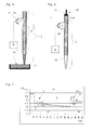
- FIG. 1 shows a vertical section through a device or system suitable for carrying out the method according to the invention, according to a first embodiment and according to a first use.
- This device comprises a fluid space 2, which communicates with a measuring space 3.
- This connection is here designed as a direct, open passage between the two chambers 2, 3.
- the internal pressure of the measuring chamber 3 is monitored by a pressure sensor 4, which is connected to a computer 8.
- the pressure sensor could be directly connected to the fluid space (see Fig. 2).
- a first part 5 of the fluid space which here comprises the entire fluid space 2 of a pipette or pipette tip, is here filled with a gas.
- the pipette tip touches the surface of a liquid 1, which is presented as a sample 6 in a container 13.
- Such containers may have any shape and content and are e.g. designed as sample tubes, wells of a microplate, troughs, or Petri dishes.
- FIG. 2 shows a vertical section through a device or system suitable for carrying out the method according to the invention, according to a second embodiment and according to a second use.
- This device comprises a fluid space 2, which communicates with a measuring space 3.
- the fluid space 2 also forms the measuring space 3 at the same time.
- the internal pressure of the measuring space 3 is monitored by a pressure sensor 4, which is connected to a computer 8.
- the fluid space 2 of a pipette or pipette tip touches the surface of a liquid 1.
- the fluid column 7, which here is completely formed by a system liquid 11, experiences pressure variations or pressure fluctuations.
- FIG. 3 shows a vertical section through a device or system suitable for carrying out the method according to the invention, according to a third embodiment and according to a third use.
- This device comprises a fluid space 2, which communicates with a measuring space 3.
- This connection is here as a sealingly arranged between the two rooms 2.3, flexible diaphragm 29 is formed.
- the internal pressure of the measuring chamber 3 is monitored by a pressure sensor 4, which is connected to a computer 8.
- a first part 5 of the fluid space which here comprises only the rear part of the fluid space 2 of a pipette or pipette tip, is here filled with an air-gap 39 and with system liquid 11.
- the system liquid 11 can also be omitted here.
- the first embodiment see Fig.
- the air-gap 39 is arranged in the region of the measuring space 3.
- this is not mandatory because the membrane 29 protects the measuring space 3 from penetrating sample or system liquid.
- the pipette tip is slightly immersed in the liquid 1 and sample liquid 6 has already been drawn up into the pipette tip.
- the fluid column 7, which in this case comprises sample liquid 6, a gas and possibly system liquid 11 experiences pressure changes or pressure fluctuations.
- FIG. 4 shows a vertical section through a device or system suitable for carrying out the method according to the invention, according to a third embodiment and according to a fourth use.
- This device is the same as that shown in Fig. 3.
- the entire fluid space 2 of a pipette or pipette tip is here filled in the region of the tip with an air-gap 39 and otherwise with system liquid 11.
- the membrane 29 protects the measuring space 3 from penetrating system liquid 11.
- the pipette tip is slightly immersed in the liquid 1.
- the fluid column 7, which here comprises a gas and system fluid 11 experiences pressure variations or pressure fluctuations.
- FIG. 5 shows a vertical section through a device or system suitable for carrying out the method according to the invention, according to a preferred third embodiment and according to a fifth use.
- This device is the same design as that shown in Figures 3 and 4.
- the entire fluid space 2 of a pipette or pipette tip, here in the region of the tip is already filled with sample liquid 6, which by means of a small air-gap 39 of the system liquid 11 is disconnected.
- the membrane 29 protects the measuring space 3 from penetrating system liquid 11.
- the measuring space 3 can be filled with a gas (eg air or N 2 ). If the measuring space is filled with a liquid (eg oil, water), it may additionally comprise a gas bubble which separates the sensor from the liquid.
- the pipette tip is still slightly immersed in the liquid 1.
- the fluid column 7, which here comprises a gas and system liquid 11 experiences pressure variations or pressure fluctuations.
- the pipette is connected via a line to a pump (both not shown).
- a pump both not shown.
- Such pumps may be arbitrarily selected and are designed to dispense larger volumes in the microliter range or in the small volume range from nano to picoliter, depending on the type.
- the pressure changes described also effect in each case in the measuring chamber 3, which is pneumatically connected to the fluid column 7, pressure changes which are recorded by the pressure sensor 4 and converted into measurement signals.
- These measurement signals are processed by the computer 8 and displayed as a pressure curve 9 (see, e.g., Fig. 7).
- the course of this pressure curve 9 can then be compared with the course of known pressure curves. Because each of these pressure curves is characteristic of a particular sample liquid 6, the currently present liquid 1 can be classified based on this comparison.
- a significant advantage of the present invention is thus that a hitherto unknown sample liquid can be characterized by a one-time test and a simple comparison and assigned to a liquid class without many individual parameters of this sample liquid having to be
- FIG. 6 shows a vertical section through a device or system suitable for carrying out the method according to the invention, according to a third embodiment with a piston pump.
- the embodiment and the use correspond to those described in connection with FIG. 4.
- the fluid column 7, which comprises an air-gap 39 in the region of the pipette tip, is essentially formed by the system fluid 11.
- first line 19 which is also filled with system liquid
- the fluid column 7 is extended to the piston 21 of a piston pump 20.
- This piston pump 20 is used to generate a negative pressure in the fluid space 2 for aspirating and generating an overpressure in the fluid chamber 2 for dispensing liquid samples 6.
- This piston pump 20 also serves as a pulse unit 17, with which the substantially homogeneous fluid column 7, extending to the air -gap 39 extends, can be vibrated.
- the membrane 29 protects the measuring space 3 from penetrating system liquid.
- the pipette tip is currently removed from a sample liquid 6, so that the situation depicted here occurs when the pipette is prepared with system liquid and an air-gap for sample taking.
- the pressure sensor 4 is used to detect any gas bubbles in the fluid column, which can be detected by characteristic changes in the caused by the pulse unit 17 pressure fluctuations.
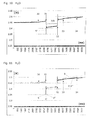
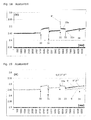
- FIG. 7 shows a pressure curve 9 in which the measured pressure values (in volts) are plotted against a time axis (in milliseconds).
- the pressure curve 9 shows characteristic pressure changes, which were generated in this case in a filled with water as the system liquid 11 fluid column.
- the sample liquid 6 was also water which was separated from the system liquid 11 by an air-gap 39 (compare embodiment without membrane 29 according to Fig. 1, but use according to Fig. 3).
- the beginning of the aspiration in which the piston 21 of the pump 20 has been set in motion, is denoted by 31.
- This sudden, one-sided pulse which is delivered to the fluid column, generates a vibration of the fluid column, which are detected as pressure changes in the measuring chamber 3.
- the end of the aspiration is called 31a.
- This sudden, unilaterally counter-directed pulse which is delivered to the fluid column, again generates a vibration of the fluid column, which are also detected as pressure changes in the measuring chamber 3.
- the respective course of the upper and lower envelopes 37, 38 of the pressure curve 9 is characteristic of water. Aspiration over a period of about two seconds caused a pressure drop of about 0.2V.
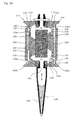
- FIG. 8 shows a vertical section through a pipetting device.
- This device or system according to the third embodiment suitable for carrying out the method according to the invention comprises a piston pump 20 (see FIG.
- This pump is preferably a "CAVRO XP3000 plus Modular Digital Pump” (Tecan Systems Inc., 2450 Zanker Road, San Jose, CA 95138, USA) or a bellows pump, such as, for example US 5,638,986 is known.
- the piston 21 is driven by the motor M.
- This device also comprises a per se known, disposable pipette tip 12, which is attached to a tubular pipette containing the fluid column 7.
- the pipette tip 12 is attached to a holder 12a.
- the fluid column 7 is formed by a system fluid 11.
- the fluid space 2 extends from the active part of the pump, ie from the piston 21, via a line 19 designed according to the device requirements, the fluid column 2 and an air-gap 39 to the tip of the pipette tip 12.
- the whole, removable pipette tip 12 is provided with a Gas (usually air) filled and slightly immersed in a liquid sample 6, which is located in a container 13.
- the immersion of the pipette tip 12 into the sample liquid 6 caused pressure changes or pressure fluctuations in the fluid column 7.
- These pressure changes cause pneumatically connected to the fluid column 7 (preferably separated by a flexible membrane 29) measuring chamber 3 also pressure changes, which are received by the pressure sensor 4 and converted into measurement signals.
- This is thus a detection of a liquid surface by means of pressure measurement. Such detection is therefore independent of whether the liquid 1 to be picked up is electrically conductive or not.
- this device comprises an additional pressure sensor 4 'in the region of the line 19, which connects the pipette with the piston pump 20 as so-called "tubing".
- This additional pressure sensor 4 ' is preferably also connected to the computer 8 (not shown).
- Alternative pipette tips include the shown disposable tips of inert plastic material, eg of inexpensive polypropylene. Also steel needles (with or without, for example, with titanium, platinum or Teflonderivaten coated tips) are also usable and are then preferably used as a fixed, non-disposable pipette tips.
- FIG. 9 shows a partial section through an electronic-mechanical variant of an alternative, pump-independent pulse unit 17 with which pressure changes in the fluid space 2 can likewise be produced.
- the line 19 is guided by a cylinder 40.
- a piston 41 is arranged with a wedge 43 which is substantially perpendicular to the closed surface of the conduit 19 movable.
- the wedge 43 is preferably made of soft plastic material and / or has a rounded edge so that the conduit 19 is not damaged. Other shapes may be selected for the wedge 43, such as spheres or bodies with flat or curved surfaces.
- a preferably solid bottom 44 closes off the cylinder 40 on the side opposite the piston 41. This movement reversibly deforms the line 19, which triggers the said pulse.
- this pulse unit can be operated independently of moving the pipette in an X, Y or Z direction and independently of the operation of the pump 20.
- This pulse unit 17 is particularly suitable for detecting gas bubbles in the system fluid 11, which is located in the fluid space 2.
- the drive is e.g. a coil 42.
- the sample liquid 6 (aspiration) was taken in each case after immersion in the liquid 1 by 10 steps with a calculated flow velocity of 180 ⁇ l / sec and for a duration of about 2 seconds.
- the pressure in dispensing 32 first increases by 0.1 V and then oscillates In turn, the pressure increases only insignificantly at the beginning 33 of the retraction of the pipette tip from the sample liquid and falls by approximately the same amount at the end 34 of the retraction of the pipette tip from the sample liquid in that the initially noted, continuous increase in pressure equals the same slope between the end points of the b ongoing activities.
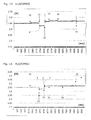
- Figure 12 shows a single characteristic pressure curve 9 "for a sample fluid with a water / DMSO mixture
- the ratio of water to dimethyl sulfoxide was 1: 1
- the pressure in the pipette, ie in the fluid space 2 and thus in the measuring chamber 3 does not increase substantially from the immersion 30.
- the pressure first drops by 0.08 V and then oscillates asymmetrically to a pressure reduced by about 0.025 V.
- the pressure at dispensing 32 first increases by 0.1 V and then vibrates asymmetrically to a pressure that is about 0.015 V higher.
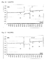
- 15 shows three characteristic pressure curves 9, 9 ', 9 "for the sample liquid DMSO The high reproducibility of the results is obvious.
- 16 shows a single characteristic pressure curve 9 "for a sample liquid with a water / polyethylene glycol mixture (7% PEG in water) .
- the pressure in the pipette ie in the fluid space 2 and thus in the measuring space 3, increases the immersion 30 slowly and continuously, which can be attributed to a capillary action of the pipette tip and thus in this penetrating water / PEG mixture.
- the pressure In aspiration 31, the pressure first drops by 0.11 V and then oscillates extremely asymmetrically to a pressure reduced by about 0.037 V.
- the pressure at dispensing 32 first increases by 0.13 V and then again oscillates extremely asymmetrically to a pressure that is about 0.037 V higher.
- the pressure increases only insignificantly and drops by about the same amount at the end 34 of retraction of the pipette tip from the sample liquid. It is noticeable that the initially noted continuous increase in pressure continues with the same slope between the endpoints of the activities described.
- the pressure drops by 0.017 V to an inflection point 33b and increases until the end 34 of the retraction of the pipette tip from the sample liquid. to fall there by a small amount.
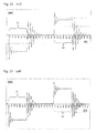
- FIGS. 22 and 23 respectively show flow changes in the pipette of a pipetting device or pipetting system suitable for carrying out the method according to the invention when aspirating and dispensing a water sample or an air sample.
- Flow values [ ⁇ ] are shown as a function of time [t]. The flow values were normalized and are not given in absolute numbers. The time values are given in milliseconds.
- FIGS. 22 and 22 both show a symmetrical vibration behavior of the flow value typical of water (system fluid). This vibration behavior is reminiscent of the pressure fluctuations, which in a system were measured with water sample (see Fig. 10), whereas here no drift behavior of the measured values was found.
- the two measured flow curves for water and for air are so similar that only a graphical comparison (see Fig. 24) or a mathematical processing (see Fig. 25) makes clear differences visible.
- Figure 24 shows a superposition of the flow variation curves of Figure 22 "water” and 23 "air".
- the flow curve “air” (thick line) swings faster and also goes faster in a state of equilibrium than the flow curve "water” (thin line).
- Figure 25 shows a subtraction representation of the flow variation curves Figure 22 "Water” minus 23 "Air”.
- the subtraction was chosen here, so that one obtains an impressive difference image of the two curves. This clearly shows that different samples also cause different flow curves. It is now up to the individual user to evaluate the characteristic flow curve of a sample directly and compare it with a stored flow curve of a known sample, e.g. by a superposition as in Fig. 24 wants to compare. Alternatively or in combination with a direct comparison, mathematical operations, such as. e.g. in Fig. 25, for comparison purposes.
- FIG. 26 shows a sectional view through a micromembrane pump for generating a negative pressure in the pipette tip for aspirating a liquid sample and for generating an overpressure in the pipette tip for dispensing a liquid sample, which is shown in FIG DE 102 38 564 A1 is known.
- This known from the prior art pipetting device has two micropumps with passive flap valves.
- This pipetting device has a first and a second micropump 110 a and 110 b, whose operation in FIG DE 102 38 564 A1 is described in detail.
- Both micropumps each include a piezoelectric actuator 126, which ale a piezoelectric ceramic layer over a large area on a thin membrane 128 arranged is and serve to reduce or enlarge the pump chamber 116. All numerals in Fig. 26 have been used by DE 102 38 564 A1 and are described there.
- the current consumption of this piezoelectric ceramic layer depends on the hydrostatic pressure which generates the liquid to be pipetted in the pipette tip.
- the capillary effects, the surface tension and the vapor pressure of the liquid to be pipetted also affect the current consumption of the piezoelectric ceramic layer when aspirating or dispensing a liquid sample.
- the measurement and recording of the course of this current consumption can therefore also be used for classifying a sample liquid according to the invention.
- a micropump with active valves could also be used for the same purpose as those in US Pat DE 102 38 564 A1 in connection with Figures 2 and 3 are disclosed.
- the current consumption of the piezoelectric ceramic layer would be used in the aspiration of a sample liquid for classifying this liquid according to the invention, because it detects the change of a selected, measurable and physically justified, virtual parameter as a data set typical for this liquid 1.
- the data set with the changes of this virtual parameter then constitutes, as in all other described embodiments, a quasi physical "fingerprint" or parameter "F" of this liquid to be pipetted.
- This parameter "F” thus represents the sum of all classical physical parameters when aspirating and dispensing a liquid, act on it.
- the pipette tip 134 may be a steel tip or a combination of a tip adapter and a disposable pipette tip mounted thereon.
- the micropump can (as in DE 102 38 564 A1 disclosed) for conveying gases, such as air, but also used to convey a system liquid; wherein this system liquid is preferably separated from the sample liquid to be pipetted by an air-gap.
Landscapes
- Health & Medical Sciences (AREA)
- Chemical & Material Sciences (AREA)
- Life Sciences & Earth Sciences (AREA)
- General Health & Medical Sciences (AREA)
- Physics & Mathematics (AREA)
- Analytical Chemistry (AREA)
- Biochemistry (AREA)
- General Physics & Mathematics (AREA)
- Immunology (AREA)
- Pathology (AREA)
- Chemical Kinetics & Catalysis (AREA)
- Clinical Laboratory Science (AREA)
- Hydrology & Water Resources (AREA)
- Automatic Analysis And Handling Materials Therefor (AREA)
- Sampling And Sample Adjustment (AREA)
- Feeding, Discharge, Calcimining, Fusing, And Gas-Generation Devices (AREA)
Abstract
Description
Die Erfindung betrifft gemäss dem Oberbegriff des unabhängigen Anspruchs 1 ein Verfahren zum Klassifizieren einer Flüssigkeit, bei dem ein Fluidraum mit einem Messraum in Verbindung steht und der Innendruck dieses Messraums mit einem Druckfühler überwacht wird, und bei dem zumindest ein erster Teil dieses Fluidraums mit einer Probe dieser Flüssigkeit in Fluidverbindung gebracht wird. Die Erfindung betrifft zudem eine entsprechende Vorrichtung und ein Computerprogrammprodukt zum Klassifizieren einer Flüssigkeit. Besonders bevorzugte Ausführungsformen des erfindungsgemässen Verfahrens bzw. der erfindungsgemässen Vorrichtung beziehen sich auf ein Pipetiergerät zum Liquid Handling von Flüssigkeitsproben.According to the preamble of
Die Erfindung umfasst somit ein Verfahren zum Klassifizieren von Flüssigkeiten in einem Pipetiergerät zur Aufnahme (Aspiration) und zur Abgabe (Dispens) von Flüssigkeitsvolumina wie z.B. Proben von menschlichen Körperflüssigkeiten. Ein solches Pipetiergerät umfasst eine Pipettenspitze, die an einer Pumpe angeschlossen ist.The invention thus comprises a method for classifying liquids in a pipetting device for receiving (aspiration) and dispensing (dispensing) of liquid volumes, such as samples of human body fluids. Such a pipetting device comprises a pipette tip which is connected to a pump.
Industriezweige, die sich z.B. in der pharmazeutischen Forschung bzw. in der klinischen Diagnostik mit biochemischen Techniken befassen, benötigen Anlagen zum Verarbeiten von Flüssigkeitsvolumina und Flüssigkeitsproben. Automatisierte Anlagen umfassen üblicherweise ein einzelnes Pipetiergerät oder mehrere Pipetiergeräte, welche an Flüssigkeitsbehältern eingesetzt werden, die sich auf dem Arbeitstisch einer Arbeitsstation befinden. Solche Arbeitsstationen sind oftmals fähig, unterschiedlichste Arbeiten an diesen Flüssigkeitsproben auszuführen, wie z.B. optische Messungen, Pipettieren, Waschen, Zentrifugieren, Inkubieren und Filtrieren. Ein oder mehrere Roboter, operieren diese nun nach kartesischen oder polaren Koordinaten, können zur Probenbearbeitung an einer solchen Arbeitsstation eingesetzt werden. Solche Roboter können Flüssigkeitsbehälter, wie. z.B. Probenröhrchen oder Mikroplatten tragen und umplatzieren. Solche Roboter können auch als sogenannte "robotic sample processor" (RSP), wie z.B. als Pipetiergerät zum Aspirieren und Dispensieren, oder als Dispenser zum Verteilen von Flüssigkeitsproben eingesetzt werden. Vorzugsweise werden solche Anlagen durch einen Rechner kontrolliert und gesteuert. Ein entscheidender Vorteil solcher Anlagen besteht darin, dass grosse Zahlen von Flüssigkeitsproben über lange Zeiträume von Stunden und Tagen automatisch bearbeitet werden können, ohne dass ein menschlicher Operator in den Bearbeitungsprozess eingreifen muss.Industries, e.g. in pharmaceutical research and in clinical diagnostics with biochemical techniques, need facilities for the processing of liquid volumes and liquid samples. Automated plants typically include a single pipetting device or multiple pipetting devices that are used on liquid containers located on the workstation of a workstation. Such workstations are often capable of performing a wide variety of work on these fluid samples, such as e.g. optical measurements, pipetting, washing, centrifuging, incubating and filtering. One or more robots, now operating on Cartesian or polar coordinates, can be used to process samples at such a workstation. Such robots can be liquid containers, such as. e.g. Wear sample tubes or microplates and reposition. Such robots may also be referred to as a so-called "robotic sample processor" (RSP), such as e.g. as a pipetting device for aspirating and dispensing, or used as a dispenser for distributing liquid samples. Preferably, such systems are controlled and controlled by a computer. A key advantage of such systems is that large numbers of fluid samples can be automatically processed over long periods of hours and days without the need for a human operator to interfere with the machining process.
Aus dem Stand der Technik (vgl. z.B.
Beim Pipettieren von Flüssigkeiten tritt oft die Frage nach der Art, d.h. nach den physikalischen Merkmalen oder Konstanten dieser Flüssigkeit auf. Es ist deshalb aus dem Stand der Technik bekannt, dass Flüssigkeiten an Hand ihrer physikalischen Konstanten, wie z.B. Oberflächenspannung, Viskosität oder Dampfdruck klassifiziert werden. An Hand der entsprechenden Klassifikation können dann die geeigneten Pipetierparameter bestimmt und diese Flüssigkeiten mit verbesserter Präzision pipettiert werden.When pipetting liquids, the question often arises of the type, ie the physical characteristics or constants of this liquid. It is therefore known from the prior art that liquids are based on their physical constants, such as surface tension, viscosity or vapor pressure be classified. On the basis of the appropriate classification, the appropriate pipetting parameters can then be determined and these liquids pipetted with improved precision.
Aus dem Dokument
Wie weiter oben erläutert, spielen aber auch andere Parameter beim Pipettieren eine wesentliche Rolle. So ist wegen des unterschiedlichen Dampfdrucks bekannt, dass Proben von Wasser oder Aceton in völlig unterschiedlicher Weise pipettiert werden müssen. Die Oberflächenspannung dieser Lösungsmittel ist ebenfalls sehr unterschiedlich. Zur Illustration sind in der Tabelle 1 die Viskosität, der Dampfdruck und die Oberflächenspannung für einige gebräuchliche Lösungsmittel angegeben.
Aus dieser Tabelle 1 ist ersichtlich, dass die Oberflächenspannung von Aceton und Ethanol sehr ähnlich ist. Trotzdem sind diese beiden Lösungsmittel wegen den sehr unterschiedlichen Werten ihrer Parameter Viskosität und/oder Dampfdruck beim Pipetieren nicht gleich zu behandeln. Es liegt deshalb auf der Hand, dass es kaum genügt, nur einen Parameter zu bestimmen, um solch unterschiedliche Lösungsmittel, die in allen biochemischen Labors routinemässig verwendet werden, automatisch und zuverlässig Pipettieren zu können. Das Erfassen aller dieser Parameter (und allenfalls noch zusätzlicher Parameter, wie z.B. die Benetzbarkeit der Pipettenspitze in Abhängigkeit der zu pipettierenden Flüssigkeit bzw. des für die Pipettenspitze verwendeten Materials) würde aber einen zu grossen maschinellen und zeitlichen Aufwand bedingen. Dies vor allem dann, wenn im Fall einer automatisierten Arbeitsstation der Durchsatz von Hunderten oder Tausenden von Proben innert möglichst kurzer Zeit gewährleistet sein muss. Erschwerend kommt sicherlich dazu, wenn es sich bei den Lösungsmitteln bzw. Flüssigkeitsproben um unbekannte Zusammensetzungen mit unbekannten physikalischen Parametern handelt, die ebenfalls möglichst automatisch pipettiert werden sollten.From Table 1 it can be seen that the surface tension of acetone and ethanol is very similar. Nevertheless, these two solvents are due The very different values of their parameters viscosity and / or vapor pressure during pipetting not to treat the same. It is therefore obvious that it is scarcely sufficient to determine only one parameter in order to be able to automatically and reliably pipette such different solvents routinely used in all biochemical laboratories. The capture of all these parameters (and possibly even additional parameters such as the wettability of the pipette tip depending on the liquid to be pipetted or the material used for the pipette tip) would, however, require too much mechanical and time expenditure. This is especially true if, in the case of an automated workstation, the throughput of hundreds or thousands of samples must be guaranteed within the shortest possible time. To make matters worse when it comes to the solvents or liquid samples are unknown compositions with unknown physical parameters, which should also be pipetted as automatically as possible.
Der vorliegenden Erfindung liegt deshalb die Aufgabe zu Grunde, ein alternatives Verfahren vorzuschlagen, mit welchem Flüssigkeitsproben auf einfache Art und Weise klassifiziert und nach Bedarf pipettiert werden können.The present invention is therefore based on the object to propose an alternative method, with which liquid samples can be classified in a simple manner and pipetted as needed.
Diese Aufgabe wird beispielsweise dadurch gelöst, dass ein Verfahren zum Klassifizieren einer Flüssigkeit vorgeschlagen wird, bei dem ein Fluidraum mit einem Messraum in Verbindung steht und der Innendruck dieses Messraums mit einem Druckfühler überwacht wird, und bei dem zumindest ein erster Teil dieses Fluidraums mit einer Probe dieser Flüssigkeit in Fluidverbindung gebracht wird. Das erfindungsgemässe Verfahren ist in diesem Fall dadurch gekennzeichnet, dass in einer im Fluidraum angeordneten, im wesentlichen zusammenhängende Fluidsäule Druckveränderungen erzeugt werden, wobei diese Druckveränderungen in dem pneumatisch mit der Fluidsäule verbundenen Messraum entsprechende Druckveränderungen bewirken, welche vom Druckfühler aufgenommen und in Messsignale umgewandelt werden, welche Messsignale von einem Rechner verarbeitet und als Druckkurve wiedergegeben werden, und wobei der Verlauf dieser Druckkurve mit dem Verlauf bekannter Druckkurven verglichen und die Flüssigkeit an Hand dieses Vergleichs klassifiziert wird.This object is achieved, for example, by proposing a method for classifying a liquid, in which a fluid space communicates with a measuring space and the internal pressure of this measuring space is monitored by a pressure sensor, and in which at least a first part of this fluid space with a sample this fluid is brought into fluid communication. In this case, the method according to the invention is characterized in that pressure changes are produced in a substantially continuous fluid column arranged in the fluid space, wherein these pressure changes in the measuring chamber pneumatically connected to the fluid column cause corresponding pressure changes which are picked up by the pressure sensor and converted into measuring signals. which measurement signals are processed by a computer and reproduced as a pressure curve, and the course of this pressure curve compared with the course of known pressure curves and the liquid is classified on the basis of this comparison.
Das erfinderische Verfahren basiert somit auf der grundsätzlichen Überlegung, dass eine zu pipettierende Flüssigkeit an Hand von Veränderungen eines ausgewählten, messbaren und physikalisch begründeten, virtuellen Parameters als ein für diese Flüssigkeit typischer Datensatz erfasst wird; dass dieser typische Datensatz des ausgewählten virtuellen Parameters mit entsprechenden Datensätzen bekannter Flüssigkeiten verglichen wird, und dass die Flüssigkeit an Hand dieses Vergleichs klassifiziert wird. Dieser ausgewählte virtuelle Parameter ist aber nicht ein klassischer Parameter, wie die Viskosität, der Dampfdruck oder die Oberflächenspannung; er wird aber unter anderem durch alle diese klassischen Parameter beeinflusst. Tatsächlich wird - in einer Art "Annäherung an die Erfahrung eines Experimentators" - summarisch festgestellt, wie sich die Flüssigkeit in einem bekannten Pipetier-System verhält. Dies wurde oben durch das Erfassen der Veränderung des Pipetten-Innendrucks ausgeführt. Erfindungsgemäss kann dieses Verfahren bereits beim Eintauchen in eine zu pipettierende Flüssigkeit oder während dem Aspirieren dieser Flüssigkeit ausgeführt werden.The inventive method is thus based on the fundamental consideration that a liquid to be pipetted is detected on the basis of changes of a selected, measurable and physically justified, virtual parameter as a data set typical for this fluid; that this typical record of the selected virtual parameter is compared to corresponding records of known liquids, and that the liquid is classified based on this comparison. However, this selected virtual parameter is not a classical parameter such as viscosity, vapor pressure or surface tension; but it is influenced, among other things, by all these classical parameters. In fact, in a kind of "approach to the experience of an experimenter", it is summarily determined how the fluid behaves in a known pipetting system. This was done above by detecting the change in pipette internal pressure. According to the invention, this process can be carried out already when immersing in a liquid to be pipetted or during the aspiration of this liquid.
Weitere entsprechend der vorliegenden Erfindung ausgewählte virtuelle Parameter, die zu vergleichbaren Resultaten führen, umfassen das Erfassen der Veränderungen dieses ausgewählten virtuellen Parameters beim Aspirieren der zu pipettierenden Flüssigkeit in Form:
- des aktuellen Flusses der Systemflüssigkeit oder der zu pipettierenden Flüssigkeit in einer Pipette;
- des Gesamtgewichts eines Behälters, aus dem heraus eine zu pipettierende Flüssigkeit aspiriert wird;
- der Leistungsaufnahme des DC-Motors, der beim Aspirieren der zu pipettierenden Flüssigkeit zum Bewegen des Pumpenkolbens verwendet wird;
- der Leistungsaufnahme des Piezoantriebs einer Mikromembranpumpe, die beim Aspirieren der zu pipettierenden Flüssigkeit zum Erzeugen eines Unterdruckes in der Pipettenspitze verwendet wird.
- the current flow of the system liquid or the liquid to be pipetted in a pipette;
- the total weight of a container from which a liquid to be pipetted is aspirated;
- the power consumption of the DC motor used in aspirating the liquid to be pipetted to move the pump piston;
- the power consumption of the piezo drive of a micromembrane pump, which is used in aspirating the liquid to be pipetted for generating a negative pressure in the pipette tip.
Weitere entsprechend der vorliegenden Erfindung ausgewählte virtuelle Parameter, die zu vergleichbaren Resultaten führen, umfassen das Erfassen der Veränderungen dieses ausgewählten virtuellen Parameters beim Eintauchen in eine zu pipettierende Flüssigkeit oder während dem Aspirieren dieser Flüssigkeit in Form:
- der Tonhöhe von in einen Gasraum in der Pipette eingekoppelten Schallwellen, wobei die Schallwellen z.B. direkt über die Pipettenwand oder über ein Mikrophon in diesen sich innerhalb der Pipette befindenden Gasraum geleitet werden können;
- der Phasengrenzenposition einer sich in der Pipette befindenden Systemflüssigkeit oder zu pipettierenden Flüssigkeit. Diese Phasengrenzenposition kann z.B. mit optischen Mitteln, wie dem Einkoppeln oder Streuen von Lichtwellen detektiert und aufgezeichnet werden.
- the pitch of sound waves coupled into a gas space in the pipette, wherein the sound waves can be conducted eg directly via the pipette wall or via a microphone into this gas space located inside the pipette;
- the phase boundary position of a system liquid in the pipette or liquid to be pipetted. This phase boundary position can be detected and recorded, for example, by optical means, such as the coupling or scattering of light waves.
Diese Aufgabe wird somit gemäss einem ersten Aspekt dadurch gelöst, dass ein Verfahren mit den Merkmalen des Anspruchs 1 vorgeschlagen wird. Diese Aufgabe wird gemäss einem zweiten Aspekt dadurch gelöst, dass ein besonders bevorzugtes Verfahren mit den Merkmalen des Anspruchs 3 vorgeschlagen wird. Diese Aufgabe wird gemäss einem dritten Aspekt dadurch gelöst, dass eine Vorrichtung mit den Merkmalen des Anspruchs 17 vorgeschlagen wird. Zusätzliche, bevorzugte erfinderische Merkmale ergeben sich jeweils aus den abhängigen Ansprüchen.This object is thus achieved according to a first aspect in that a method with the features of
Eine derart klassifizierte Flüssigkeit kann anschliessend korrekt pipettiert, d.h. mit einer Pipette in einer bestimmten Menge bzw. in einem bestimmten Volumen in einen Behälter, z.B. ein Well einer Mikroplatte, abgegeben bzw. dispensiert werden. Zu diesem Zweck wird an Hand der erfindungsgemässen Klassifizierung der Flüssigkeit ein Parametersatz für das Ansteuern des Pipetiergeräts zum Abgeben von Flüssigkeitsproben ausgewählt. Diese Auswahl erfolgt manuell oder automatisch dadurch, dass aus einer Bibliothek von Parametersätzen auf Grund von festgelegten Toleranzbereichen derjenige Parametersatz ausgewählt wird, der den gestellten Anforderungen am nächsten kommt.A liquid classified in this way can then be pipetted correctly, ie dispensed or dispensed with a pipette in a certain amount or in a certain volume into a container, eg a well of a microplate. For this purpose, a parameter set for controlling the pipetting device for dispensing liquid samples is selected on the basis of the classification of the liquid according to the invention. This selection is made manually or automatically by selecting from a library of parameter sets, on the basis of specified tolerance ranges, the parameter set which comes closest to the set requirements.
Das erfindungsgemässe Verfahren wird nun an Hand von schematischen, den Umfang der Erfindung nicht beschränkenden Zeichnungen von beispielhaften Ausführungsformen im Detail erläutert. Dabei zeigen:
- Fig. 1
- einen Vertikalschnitt durch ein zum Ausführen des erfindungsgemässen Verfahrens geeigneten Geräts bzw. Systems, gemäss einer ersten Ausführungsform und gemäss einer ersten Verwendung;
- Fig. 2
- einen Vertikalschnitt durch ein zum Ausführen des erfindungsgemässen Verfahrens geeigneten Geräts bzw. Systems, gemäss einer zweiten Ausführungsform und gemäss einer zweiten Verwendung;
- Fig. 3
- einen Vertikalschnitt durch ein zum Ausführen des erfindungsgemässen Verfahrens geeigneten Geräts bzw. Systems, gemäss einer dritten Ausführungsform und gemäss einer dritten Verwendung;
- Fig. 4
- einen Vertikalschnitt durch ein zum Ausführen des erfindungsgemässen Verfahrens geeigneten Geräts bzw. Systems, gemäss einer dritten Ausführungsform und gemäss einer vierten Verwendung;
- Fig. 5
- einen Vertikalschnitt durch ein zum Ausführen des erfindungsgemässen Verfahrens geeigneten Geräts bzw. Systems, gemäss einer dritten Ausführungsform und gemäss einer fünften Verwendung;
- Fig. 6
- einen Vertikalschnitt durch ein zum Ausführen des erfindungsgemässen Verfahrens geeigneten Geräts bzw. Systems, gemäss einer dritten Ausführungsform mit einer Kolbenpumpe;
- Fig. 7
- Druckveränderungen im Messraum eines zum Ausführen des erfindungsgemässen Verfahrens geeigneten Pipetiergeräts bzw. Pipetiersystems, die durch ein für eine bestimmte Fluidsäule charakteristisches Schwingungsverhalten (hier für Wasser) erzeugbar sind;
- Fig. 8
- einen Vertikalschnitt durch ein zum Ausführen des erfindungsgemässen Verfahrens geeigneten Geräts bzw. Systems, gemäss einer dritten Ausführungsform mit einer motorisierten Kolbenpumpe;
- Fig. 9
- einen Teilschnitt durch eine elektronmechanische Variante einer alternativen, pumpen-unabhängigen Impulseinheit, mit welcher Druckveränderungen im Fluidraum erzeugbar sind;
- Fig. 10
- den Verlauf einer typischen Druckkurve für Wasser als Probenflüssigkeit;
- Fig. 11
- eine annährende Superposition von drei individuellen, mit Wasser erzielten Druckkurven;
- Fig. 12
- den Verlauf einer typischen Druckkurve für ein Wasser/DMSO-Gemisch als Probenflüssigkeit;
- Fig. 13
- eine annährende Superposition von drei individuellen, mit dem Wasser/DMSO - Gemisch (1:1) erzielten Druckkurven;
- Fig. 14
- den Verlauf einer typischen Druckkurve für DMSO als Probenflüssigkeit;
- Fig. 15
- eine annährende Superposition von drei individuellen, mit DMSO erzielten Druckkurven;
- Fig. 16
- den Verlauf einer typischen Druckkurve für ein Wasser/PEG-Gemisch (7% PEG in Wasser) als Probenflüssigkeit;
- Fig. 17
- eine annährende Superposition von drei individuellen, mit dem Wasser/PEG - Gemisch erzielten Druckkurven;
- Fig. 18
- den Verlauf einer typischen Druckkurve für Acetonitril als Probenflüssigkeit;
- Fig. 19
- eine annährende Superposition von vier individuellen, mit Acetonitril erzielten Druckkurven;
- Fig. 20
- den Verlauf einer typischen Druckkurve für Aceton als Probenflüssigkeit;
- Fig. 21
- eine annährende Superposition von vier individuellen, mit Aceton erzielten Druckkurven.
- Fig. 22
- Flussveränderungen in der Pipette eines zum Ausführen des erfindungsgemässen Verfahrens geeigneten Pipetiergeräts bzw. Pipetiersystems beim Aspirieren und Dispensieren einer Wasserprobe;
- Fig. 23
- Flussveränderungen in der Pipette eines zum Ausführen des erfindungsgemässen Verfahrens geeigneten Pipetiergeräts bzw. Pipetiersystems beim Aspirieren und Dispensieren einer Luftprobe;
- Fig. 24
- eine Superposition der Flussveränderungs-Kurven von Fig. 22 "Wasser" und 23 "Luft";
- Fig. 25
- eine Subtraktionsdarstellung der Flussveränderungs-Kurven Fig. 22 "Wasser" minus 23 "Luft";
- Fig. 26
- eine Schnittdarstellung durch eine Mikromembranpumpe zum Erzeugen eines Unterdrucks in der Pipettenspitze zum Aspirieren einer Flüssigkeitsprobe und zum Erzeugen eines Überdrucks in der Pipettenspitze zum Dispensieren einer Flüssigkeitsprobe.
- Fig. 1
- a vertical section through a device or system suitable for carrying out the method according to the invention, according to a first embodiment and according to a first use;
- Fig. 2
- a vertical section through a device or system suitable for carrying out the method according to the invention, according to a second embodiment and according to a second use;
- Fig. 3
- a vertical section through a device or system suitable for carrying out the method according to the invention, according to a third embodiment and according to a third use;
- Fig. 4
- a vertical section through a device or system suitable for carrying out the method according to the invention, according to a third embodiment and according to a fourth use;
- Fig. 5
- a vertical section through an apparatus or system suitable for carrying out the method according to the invention, according to a third embodiment and according to a fifth use;
- Fig. 6
- a vertical section through a device or system suitable for carrying out the method according to the invention, according to a third embodiment with a piston pump;
- Fig. 7
- Pressure changes in the measuring space of a pipetting device or pipetting system suitable for carrying out the method according to the invention, which can be generated by a vibration characteristic characteristic of a specific fluid column (in this case for water);
- Fig. 8
- a vertical section through a device or system suitable for carrying out the method according to the invention, according to a third embodiment with a motorized piston pump;
- Fig. 9
- a partial section through an electron mechanical variant of an alternative, pump-independent pulse unit with which pressure changes in the fluid space can be generated;
- Fig. 10
- the course of a typical pressure curve for water as a sample liquid;
- Fig. 11
- an approximate superposition of three individual water pressure curves;
- Fig. 12
- the course of a typical pressure curve for a water / DMSO mixture as a sample liquid;
- Fig. 13
- an approximate superposition of three individual pressure curves obtained with the water / DMSO mixture (1: 1);
- Fig. 14
- the course of a typical pressure curve for DMSO as a sample liquid;
- Fig. 15
- an approximate superposition of three individual pressure curves obtained with DMSO;
- Fig. 16
- the course of a typical pressure curve for a water / PEG mixture (7% PEG in water) as a sample liquid;
- Fig. 17
- an approximate superposition of three individual pressure curves obtained with the water / PEG mixture;
- Fig. 18
- the course of a typical pressure curve for acetonitrile as a sample liquid;
- Fig. 19
- an approximate superposition of four individual pressure curves obtained with acetonitrile;
- Fig. 20
- the course of a typical pressure curve for acetone as a sample liquid;
- Fig. 21
- an approximate superposition of four individual pressure curves obtained with acetone.
- Fig. 22
- Flow changes in the pipette of a pipetting device or pipetting system suitable for carrying out the method according to the invention when aspirating and dispensing a water sample;
- Fig. 23
- Flow changes in the pipette of a pipetting device or pipetting system suitable for carrying out the method according to the invention when aspirating and dispensing an air sample;
- Fig. 24
- a superposition of the flow variation curves of Fig. 22 "water" and 23 "air";
- Fig. 25
- a subtraction representation of the flow variation curves Fig. 22 "water" minus 23 "air";
- Fig. 26
- a sectional view through a micro-diaphragm pump for generating a negative pressure in the pipette tip for aspirating a liquid sample and for generating an overpressure in the pipette tip for dispensing a liquid sample.
Figur 1 zeigt einen Vertikalschnitt durch ein zum Ausführen des erfindungsgemässen Verfahrens geeigneten Geräts bzw. Systems, gemäss einer ersten Ausführungsform und gemäss einer ersten Verwendung. Diese Vorrichtung umfasst einen Fluidraum 2, der mit einem Messraum 3 in Verbindung steht. Diese Verbindung ist hier als ein direkter, offener Durchgang zwischen den beiden Räumen 2,3 ausgebildet. Der Innendruck des Messraums 3 wird mit einem Druckfühler 4 überwacht, der mit einem Rechner 8 verbunden ist. In einer alternativen Ausführungsform könnte der Druckfühler direkt mit dem Fluidraum verbunden sein (vgl. Fig. 2). Ein erster Teil 5 der Fluidraums, der hier den ganzen Fluidraum 2 einer Pipette oder Pipettenspitze umfasst, ist hier mit einem Gas gefüllt. Die Pipettenspitze berührt die Oberfläche einer Flüssigkeit 1, die als Probe 6 in einem Behälter 13 vorgelegt ist. Solche Behälter können eine beliebige Form und einen beliebigen Inhalt aufweisen und sind z.B. als Probenröhrchen, Wells einer Mikroplatte, Tröge, oder Petrischale ausgebildet. Beim Eintauchen der Pipettenspitze in die Probenflüssigkeit 6 erfährt die Fluidsäule 7, die hier ganz von einem Gas gebildet ist, Druckveränderungen bzw. Druckschwankungen.FIG. 1 shows a vertical section through a device or system suitable for carrying out the method according to the invention, according to a first embodiment and according to a first use. This device comprises a
Figur 2 zeigt einen Vertikalschnitt durch ein zum Ausführen des erfindungsgemässen Verfahrens geeigneten Geräts bzw. Systems, gemäss einer zweiten Ausführungsform und gemäss einer zweiten Verwendung. Diese Vorrichtung umfasst einen Fluidraum 2, der mit einem Messraum 3 in Verbindung steht. Tatsächlich bildet hier der Fluidraum 2 gleichzeitig auch den Messraum 3. Der Innendruck des Messraums 3 wird mit einem Druckfühler 4 überwacht, der mit einem Rechner 8 verbunden ist. Der Fluidraum 2 einer Pipette oder Pipettenspitze berührt die Oberfläche einer Flüssigkeit 1. Beim Eintauchen der Pipettenspitze in die Flüssigkeit 1 erfährt die Fluidsäule 7, die hier ganz von einer Systemflüssigkeit 11 gebildet ist, Druckveränderungen bzw. Druckschwankungen.FIG. 2 shows a vertical section through a device or system suitable for carrying out the method according to the invention, according to a second embodiment and according to a second use. This device comprises a
Figur 3 zeigt einen Vertikalschnitt durch ein zum Ausführen des erfindungsgemässen Verfahrens geeigneten Geräts bzw. Systems, gemäss einer dritten Ausführungsform und gemäss einer dritten Verwendung. Diese Vorrichtung umfasst einen Fluidraum 2, der mit einem Messraum 3 in Verbindung steht. Diese Verbindung ist hier als eine zwischen den beiden Räumen 2,3 abdichtend angeordnete, flexible Membran 29 ausgebildet. Der Innendruck des Messraums 3 wird mit einem Druckfühler 4 überwacht, der mit einem Rechner 8 verbunden ist. Ein erster Teil 5 des Fluidraums, der hier nur den hinteren Teil des Fluidraums 2 einer Pipette oder Pipettenspitze umfasst, ist hier mit einem air-gap 39 und mit Systemflüssigkeit 11 gefüllt. Die Systemflüssigkeit 11 kann hier aber auch weggelassen werden. Vorzugsweise ist, vor allem in der ersten Ausführungsform (vgl. Fig. 1), in welcher diese Verbindung als ein direkter, offener Durchgang zwischen den beiden Räumen 2,3 ausgebildet ist, das air-gap 39 in der Region des Messraums 3 angeordnet. Bei der hier vorliegenden Ausführungsform ist dies jedoch nicht zwingend, weil die Membran 29 der Messraum 3 vor eindringender Proben- oder Systemflüssigkeit schützt. Die Pipettenspitze ist etwas in die Flüssigkeit 1 eingetaucht und Probenflüssigkeit 6 wurde bereits in die Pipettenspitze aufgezogen. Beim Aufziehen bzw. Aspirieren von Probenflüssigkeit 6 erfährt die Fluidsäule 7, die hier Probenflüssigkeit 6, ein Gas und eventuell Systemflüssigkeit 11 umfasst, Druckveränderungen bzw. Druckschwankungen.FIG. 3 shows a vertical section through a device or system suitable for carrying out the method according to the invention, according to a third embodiment and according to a third use. This device comprises a
Figur 4 zeigt einen Vertikalschnitt durch ein zum Ausführen des erfindungsgemässen Verfahrens geeigneten Geräts bzw. Systems, gemäss einer dritten Ausführungsform und gemäss einer vierten Verwendung. Diese Vorrichtung ist gleich ausgebildet wie die in Fig. 3 gezeigte. Der ganze Fluidraum 2 einer Pipette oder Pipettenspitze, ist hier im Bereich der Spitze mit einem air-gap 39 und sonst mit Systemflüssigkeit 11 gefüllt. Bei der hier vorliegenden Ausführungsform schützt die Membran 29 den Messraum 3 vor eindringender Systemflüssigkeit 11. Die Pipettenspitze ist etwas in die Flüssigkeit 1 eingetaucht. Beim Eintauchen von Probenflüssigkeit 6 erfährt die Fluidsäule 7, die hier ein Gas und Systemflüssigkeit 11 umfasst, Druckveränderungen bzw. Druckschwankungen.FIG. 4 shows a vertical section through a device or system suitable for carrying out the method according to the invention, according to a third embodiment and according to a fourth use. This device is the same as that shown in Fig. 3. The
Figur 5 zeigt einen Vertikalschnitt durch ein zum Ausführen des erfindungsgemässen Verfahrens geeigneten Geräts bzw. Systems, gemäss einer bevorzugten dritten Ausführungsform und gemäss einer fünften Verwendung. Diese Vorrichtung ist gleich ausgebildet wie die in den Figuren 3 und 4 gezeigte. Der ganze Fluidraum 2 einer Pipette oder Pipettenspitze, ist hier im Bereich der Spitze bereits mit Probenflüssigkeit 6 gefüllt, welche mittels einem kleinen air-gap 39 von der Systemflüssigkeit 11 getrennt ist. Bei der hier vorliegenden Ausführungsform schützt die Membran 29 den Messraum 3 vor eindringender Systemflüssigkeit 11. Der Messraum 3 kann mit einem Gas (z.B. Luft oder N2) gefüllt sein. Falls der Messraum mit einer Flüssigkeit (z.B. Öl, Wasser) gefüllt ist, kann er zusätzlich eine Gasblase umfassen, die den Sensor von der Flüssigkeit trennt. Die Pipettenspitze ist immer noch etwas in die Flüssigkeit 1 eingetaucht. Beim Aufnehmen bzw. Aspirieren von Probenflüssigkeit 6 erfährt die Fluidsäule 7, die hier ein Gas und Systemflüssigkeit 11 umfasst, Druckveränderungen bzw. Druckschwankungen.FIG. 5 shows a vertical section through a device or system suitable for carrying out the method according to the invention, according to a preferred third embodiment and according to a fifth use. This device is the same design as that shown in Figures 3 and 4. The
In den bisher beschriebenen Figuren 1 bis 5 ist die Pipette über eine Leitung an einer Pumpe angeschlossen (beides nicht gezeigt). Solche Pumpen können beliebig ausgewählt werden und sind je nach dem zum Abgeben grösserer Volumina im Bereich von Mikrolitern oder im Bereich von kleinen Volumina im Bereich von Nano- bis Picoliter ausgebildet. Die beschriebenen Druckveränderungen bewirken jeweils im pneumatisch mit der Fluidsäule 7 verbundenen Messraum 3 ebenfalls Druckveränderungen, welche vom Druckfühler 4 aufgenommen und in Messsignale umgewandelt werden. Diese Messsignale werden von dem Rechner 8 verarbeitet und als Druckkurve 9 (vgl. z.B. Fig. 7) wiedergegeben. Der Verlauf dieser Druckkurve 9 kann daraufhin mit dem Verlauf bekannter Druckkurven verglichen werden. Weil jede dieser Druckkurven für eine bestimmte Probenflüssigkeit 6 charakteristisch ist, kann die aktuell vorliegende Flüssigkeit 1 an Hand dieses Vergleichs klassifiziert werden. Ein wesentlicher Vorteil der vorliegenden Erfindung beruht somit darin, dass durch eine einmalige Prüfung und ein einfacher Vergleich eine bisher unbekannte Probenflüssigkeit charakterisiert und einer Flüssigkeitsklasse zugeordnet werden kann, ohne dass viele einzelne Parameter dieser Probenflüssigkeit in einer entsprechenden Vielzahl von Experimenten werden müssen.In the previously described Figures 1 to 5, the pipette is connected via a line to a pump (both not shown). Such pumps may be arbitrarily selected and are designed to dispense larger volumes in the microliter range or in the small volume range from nano to picoliter, depending on the type. The pressure changes described also effect in each case in the measuring
Figur 6 zeigt einen Vertikalschnitt durch ein zum Ausführen des erfindungsgemässen Verfahrens geeigneten Geräts bzw. Systems, gemäss einer dritten Ausführungsform mit einer Kolbenpumpe. Die Ausführungsform und die Verwendung entsprechen denjenigen, die im Zusammenhang mit Fig. 4 beschrieben wurden.FIG. 6 shows a vertical section through a device or system suitable for carrying out the method according to the invention, according to a third embodiment with a piston pump. The embodiment and the use correspond to those described in connection with FIG. 4.
Hier ist die Fluidsäule 7, welche im Bereich der Pipettenspitze ein air-gap 39 umfasst im wesentlichen durch die Systemflüssigkeit 11 gebildet. Durch eine, je nach gerätebedingter Konstruktion längere oder kürzere, erste Leitung 19, welche ebenfalls mit Systemflüssigkeit gefüllt ist, wird die Fluidsäule 7 bis zum Kolben 21 einer Kolbenpumpe 20 verlängert. Diese Kolbenpumpe 20 dient zum Erzeugen eines Unterdrucks im Fluidraum 2 zum Aspirieren und zum Erzeugen eines Überdrucks im Fluidraum 2 zum Dispensieren von Flüssigkeitsproben 6. Diese Kolbenpumpe 20 dient zudem als Impulseinheit 17, mit welcher die im wesentlichen homogene Fluidsäule 7, die sich bis zum air-gap 39 erstreckt, in Schwingungen versetzt werden kann. Dabei schützt die Membran 29 den Messraum 3 vor eindringender Systemflüssigkeit. Die Pipettenspitze ist im Moment von einer Probenflüssigkeit 6 entfernt, so dass die hier Abgebildete Situation dann auftritt, wenn die Pipette mit Systemflüssigkeit und einem air-gap für eine Probenaufnahme vorbereitet wird. In dieser Phase dient der Druckfühler 4 zum Feststellen von allfälligen Gasblasen in der Fluidsäule, die durch charakteristische Veränderungen in den durch die Impulseinheit 17 hervorgerufenen Druckschwankungen entdeckt werden können.Here, the
Für Vorrichtungen, d.h. Pipetiergeräte welche sich ganz besonders gut zur Durchführung des erfindungsgemässen Verfahrens eignen, hat der Anmelder der vorliegenden Patentanmeldung am 10. Dezember 2004 unter der Nummer
Grundsätzlich erzeugen alle plötzlichen bzw. abrupten Bewegungen des die Fluidsäule 7 enthaltenden Teils des Pipetiergeräts Druckveränderungen im Messraum 3 eines zum Ausführen des erfindungsgemässen Verfahrens geeigneten Pipetiergeräts bzw. Pipetiersystems. Solche Druckveränderungen können z.B. als einzelne Druckstösse oder auch als Druckschwingungen auftreten, wobei jeder bestimmten Fluidsäule 7 ein charakteristisches Schwingungsverhalten zuordenbar ist.In principle, all sudden or abrupt movements of the part of the pipetting device containing the
Figur 7 zeigt eine Druckkurve 9, indem die gemessenen Druckwerte (in Volt) gegenüber einer Zeitachse (in Millisekunden) aufgetragen sind. Die Druckkurve 9 zeigt charakteristische Druckveränderungen, die in diesem Fall in einer mit Wasser als Systemflüssigkeit 11 gefüllten Fluidsäule erzeugt wurden. Die Probenflüssigkeit 6 war ebenfalls Wasser, das durch ein air-gap 39 von der Systemflüssigkeit 11 getrennt war (vgl. Ausführungsform ohne Membran 29 gemäss Fig. 1, aber Verwendung gemäss Fig. 3). Der Beginn der Aspiration, bei dem der Kolben 21 der Pumpe 20 in Bewegung gesetzt wurde, wird mit 31 bezeichnet. Dieser plötzliche, einseitige Impuls, der auf die Fluidsäule abgegeben wird, erzeugt eine Schwingung der Fluidsäule, welche als Druckänderungen im Messraum 3 detektiert werden. Das Ende der Aspiration wird mir 31a bezeichnet. Dieser plötzliche, einseitig gegengerichtete Impuls, der auf die Fluidsäule abgegeben wird, erzeugt wieder eine Schwingung der Fluidsäule, welche ebenfalls als Druckänderungen im Messraum 3 detektiert werden. Der jeweils gezeigte Verlauf der oberen und unteren Hüllkurven 37,38 der Druckkurve 9 ist charakteristisch für Wasser. Das Aspirieren über eine Zeit von etwa zwei Sekunden bewirkte einen Druckabfall um einen Wert, der etwa 0.2 V entspricht.FIG. 7 shows a
Figur 8 zeigt einen Vertikalschnitt durch eine Pipettiervorrichtung. Dieses zum Ausführen des erfindungsgemässen Verfahrens geeignete Gerät bzw. System gemäss der dritten Ausführungsform umfasst eine Kolbenpumpe 20 (vgl. Fig. 6). Diese Pumpe ist vorzugsweise eine "CAVRO XP3000 plus Modular Digital Pump" (Tecan Systems Inc., 2450 Zanker Road, San José, CA 95138, USA) oder eine Balgpumpe, wie sie z.B. aus
Figur 9 zeigt einen Teilschnitt durch eine elektronmechanische Variante einer alternativen, pumpen-unabhängigen Impulseinheit 17, mit welcher ebenfalls Druckveränderungen im Fluidraum 2 erzeugbar sind. Die Leitung 19 wird durch einen Zylinder 40 geführt. Im Innern dieses Zylinders 40 ist ein Kolben 41 mit einem Keil 43 angeordnet, der im wesentlichen rechtwinklig gegen die geschlossene Oberfläche der Leitung 19 bewegbar ist. Der Keil 43 ist vorzugsweise aus weichem Kunststoffmaterial und/oder weist ein abgerundete Kante auf, damit die Leitung 19 nicht beschädigt wird. Es können auch andere Formen für den Keil 43 gewählt werden, wie Kugeln oder Körper mit ebenen oder gekrümmten Flächen. Ein vorzugsweise fester Boden 44 schliesst den Zylinder 40 auf der dem Kolben 41 gegenüber liegenden Seite ab. Diese Bewegung deformiert reversibel die Leitung 19, was den besagten Impuls auslöst. Es können Einzelimpulse oder auch Impulsserien ausgelöst werden, so dass die Fluidsäule nur kurz bewegt oder aber in eine Schwingung versetzt werden kann. Vorzugsweise kann diese Impulseinheit unabhängig vom Bewegen der Pipette in einer X-, Y- oder Z-Richtung und unabhängig vom Betrieb der Pumpe 20 betrieben werden. Diese Impulseinheit 17 eignet sich vorzüglich zum Detektieren von Gasblasen in der Systemflüssigkeit 11, welche sich im Fluidraum 2 befindet. Als Antrieb dient z.B. eine Spule 42.FIG. 9 shows a partial section through an electronic-mechanical variant of an alternative, pump-
Alle im Folgenden beschriebenen Figuren zeigen eine Druckkurve 9 oder mehrere Druckkurven 9,9',9", indem die gemessenen Druckwerte (in Volt) gegenüber einer Zeitachse (in Millisekunden) aufgetragen sind. In allen Fällen wurde die Druckkurven in einer mit Wasser als Systemflüssigkeit 11 gefüllten Fluidsäule erzeugt. Die Probenflüssigkeit 6, war in allen Fällen durch ein air-gap 39 von der Systemflüssigkeit 11 getrennt (vgl. Fig. 3). In allen Figuren 10 bis 21 sind die wesentlichen Vorgänge mit den gleichen Bezugszeichen wie folgt bezeichnet:
- 30
- Eintauchen der Pipettenspitze in die Probenflüssigkeit
- 31
- Aspiration / 31a Ende der Aspiration / 31b Delay nach Aspiration / 31c Ausstoss einer Blase
- 32
- Dispens
- 33
- Beginn Zurückziehen der Pipettenspitze aus der Probenflüssigkeit
- 34
- Ende Zurückziehen der Pipettenspitze aus der Probenflüssigkeit
- 35
- Störsignale durch weitere Fahrbewegungen, bzw. Abwurf d. Pipettenspitze.
- 30
- Immerse the pipette tip in the sample fluid
- 31
- Aspiration / 31a end of aspiration / 31b delay after aspiration / 31c expulsion of a blister
- 32
- dispensation
- 33
- Start retracting the pipette tip from the sample fluid
- 34
- End Retract the pipette tip from the sample fluid
- 35
- Interference signals due to further travel movements, or ejection d. Pipette tip.
Das Aufnehmen von Probenflüssigkeit 6 (Aspiration) erfolgte jeweils nach dem eintauchen in die Flüssigkeit 1 um 10 Schritte mit einer errechneten Flussgeschwindigkeit von 180 µl/sec und während einer Dauer von ca. 2 Sekunden.The sample liquid 6 (aspiration) was taken in each case after immersion in the
Figur 10 zeigt eine einzelne charakteristische Druckkurve 9" für die Probenfüssigkeit Wasser. Der Druck in der Pipette, d.h. im Fluidraum 2 und damit im Messraum 3 steigt ab dem Eintauchen 30 langsam und kontinuierlich an, was auf eine Kapillarwirkung der Pipettenspitze und damit in diese eindringendes Wasser zurückgeführt werden kann. Bei der Aspiration 31 fällt der Druck zuerst um 0.1 V und schwingt dann symmetrisch auf einen um ca. 0.05 V erniedrigten Druck ein. Nach einer Pause 31b steigt der Druck bei dem Dispens 32 zuerst um 0.1 V an und schwingt dann wiederum symmetrisch auf einen um ca. 0.05 V höheren Druck ein. Beim Beginn 33 des Zurückziehens der Pipettenspitze aus der Probenflüssigkeit steigt der Druck nur unwesentlich an und fällt beim Ende 34 des Zurückziehens der Pipettenspitze aus der Probenflüssigkeit um etwa den gleichen Betrag. Es fällt auf, dass der anfänglich bemerkte, kontinuierliche Druckanstieg sich mit gleicher Steigung zwischen den Endpunkten der beschriebenen Aktivitäten fortsetzt.10 shows a single
Figur 11 zeigt drei charakteristische Druckkurven 9,9',9" für die Probenfüssigkeit Wasser. Die hoher Reproduzierbarkeit der Resultate ist offensichtlich.11 shows three characteristic pressure curves 9, 9 ', 9 "for the sample liquid water, the high reproducibility of the results being obvious.
Figur 12 zeigt eine einzelne charakteristische Druckkurve 9" für eine Probenfüssigkeit mit einem Wasser/DMSO-Gemisch. Das Verhältnis von Wasser zu Dimethylsulfoxid betrug 1:1. Der Druck in der Pipette, d.h. im Fluidraum 2 und damit im Messraum 3 steigt ab dem Eintauchen 30 nicht wesentlich an. Bei der Aspiration 31 fällt der Druck zuerst um 0.08 V und schwingt dann asymmetrisch auf einen um ca. 0.025 V erniedrigten Druck ein. Nach einer Pause steigt der Druck bei dem Dispens 32 zuerst um 0.1 V an und schwingt dann wiederum asymmetrisch auf einen um ca. 0.015 V höheren Druck ein. Beim Beginn 33 des Zurückziehens der Pipettenspitze aus der Probenflüssigkeit steigt der Druck nur unwesentlich an und fällt beim Ende 34 des Zurückziehens der Pipettenspitze aus der Probenflüssigkeit um etwa den gleichen Betrag. Es fällt auf, dass der Druck zwischen den Endpunkten der beschriebenen Aktivitäten konstant ist.Figure 12 shows a single
Figur 13 zeigt drei charakteristische Druckkurven 9,9',9" für die Probenfüssigkeit mit dem Wasser/DMSO-Gemisch im Verhältnis 1:1. Die hoher Reproduzierbarkeit der Resultate ist offensichtlich. Die grösste Variation betrifft den Zeitpunkt des Austauchens 35 mit der Pipettenspitze.13 shows three characteristic pressure curves 9, 9 ', 9 "for the sample liquid with the water / DMSO mixture in a ratio of 1: 1. The high reproducibility of the results is obvious The greatest variation relates to the time of exchange with the pipette tip.
Figur 14 zeigt eine einzelne charakteristische Druckkurve 9" für die Probenfüssigkeit DMSO. Der Druck in der Pipette, d.h. im Fluidraum 2 und damit im Messraum 3 steigt ab dem Eintauchen 30 um 0.015 V merkbar an. Bei der Aspiration 31 fällt der Druck zuerst um 0.066 V und schwingt dann symmetrisch in etwa um den Ausgangsdruck ein. Nach einer Pause steigt der Druck bei dem Dispens 32 zuerst um 0.1 V an und schwingt dann asymmetrisch auf einen um ca. 0.02 V höheren Druck ein. Beim Beginn 33 des Zurückziehens der Pipettenspitze aus der Probenflüssigkeit steigt der Druck nur unwesentlich an und fällt beim Ende 34 des Zurückziehens der Pipettenspitze aus der Probenflüssigkeit um etwa den gleichen Betrag. Es fällt auf, dass der Druck zwischen den Endpunkten der beschriebenen Aktivitäten konstant, mehrheitlich aber mit unterschiedlicher Steigung leicht fallend ist.14 shows a single
Figur 15 zeigt drei charakteristische Druckkurven 9,9',9" für die Probenfüssigkeit DMSO. Die hoher Reproduzierbarkeit der Resultate ist offensichtlich.
Figur 16 zeigt eine einzelne charakteristische Druckkurve 9" für eine Probenfüssigkeit mit einem Wasser/Polyethylenglykol-Gemisch (7% PEG in Wasser). Der Druck in der Pipette, d.h. im Fluidraum 2 und damit im Messraum 3 steigt ab dem Eintauchen 30 langsam und kontinuierlich an, was auf eine Kapillarwirkung der Pipettenspitze und damit in diese eindringendes Wasser/PEG-Gemisch zurückgeführt werden kann. Bei der Aspiration 31 fällt der Druck zuerst um 0.11 V und schwingt dann extrem asymmetrisch auf einen um ca. 0.037 V erniedrigten Druck ein. Nach einer Pause steigt der Druck bei dem Dispens 32 zuerst um 0.13 V an und schwingt dann wiederum extrem asymmetrisch auf einen um ca. 0.037 V höheren Druck ein. Beim Beginn 33 des Zurückziehens der Pipettenspitze aus der Probenflüssigkeit steigt der Druck nur unwesentlich an und fällt beim Ende 34 des Zurückziehens der Pipettenspitze aus der Probenflüssigkeit um etwa den gleichen Betrag. Es fällt auf, dass der anfänglich bemerkte, kontinuierliche Druckanstieg sich mit gleicher Steigung zwischen den Endpunkten der beschriebenen Aktivitäten fortsetzt.15 shows three characteristic pressure curves 9, 9 ', 9 "for the sample liquid DMSO The high reproducibility of the results is obvious.
16 shows a single
Figur 17 zeigt drei charakteristische Druckkurven 9,9',9" für die Probenfüssigkeit mit dem Wasser/PEG-Gemisch (7% PEG in Wasser). Die hoher Reproduzierbarkeit der Resultate ist offensichtlich.17 shows three characteristic pressure curves 9,9 ', 9 "for the sample liquid with the water / PEG mixture (7% PEG in water) .The high reproducibility of the results is obvious.
Figur 18 zeigt eine einzelne charakteristische Druckkurve 9" für die Probenfüssigkeit Acetonitril. Der Druck in der Pipette, d.h. im Fluidraum 2 und damit im Messraum 3 steigt ab dem Eintauchen 30 schnell um 0.027 V an und steigt langsamer werdend auf einen um ca. 0.04 V erhöhten Druck an. Bei der Aspiration 31 fällt der Druck zuerst um 0.09 V und schwingt dann beinahe symmetrisch auf einen nur um ca. 0.02 V tieferen Druck ein. Nach einer Pause steigt der Druck bei dem Dispens 32 sehr steil um 0.08 V an und schwingt extrem einseitig auf einem nur um 0.035 V höheren Zwischenniveau 33a ein. Darauf fällt der Druck beim Beginn 33 des Zurückziehens der Pipettenspitze aus der Probenflüssigkeit um 0.017 V auf einen Wendepunkt 33b ab und steigt bis zum Ende 34 des Zurückziehens der Pipettenspitze aus der Probenflüssigkeit an, um dort um einen kleinen Betrag zu fallen.18 shows a single
Figur 19 zeigt drei charakteristische Druckkurven 9,9',9" für die Probenfüssigkeit Acetonitril. Die hoher Reproduzierbarkeit der Resultate ist trotz der komplexen Druckkurven offensichtlich.19 shows three characteristic pressure curves 9,9 ', 9 "for the sample liquid acetonitrile, the high reproducibility of the results being evident despite the complex pressure curves.
Figur 20 zeigt eine einzelne charakteristische Druckkurve 9" für die Probenfüssigkeit Aceton. Der Druck in der Pipette, d.h. im Fluidraum 2 und damit im Messraum 3 steigt ab dem Eintauchen 30 um zuerst schnell um 0.03 V an und steigt dann konstant und steil auf einen um nochmals ca. 0.023 V erhöhten Druck an. Beim Aspirationsbeginn 31 fällt der Druck zuerst um 0.076 V und schwingt dann symmetrisch auf einen um ca. 0.04 V höheren Druck ein, um sofort wieder konstant und steil auf den Wert vor dem Aspirationsbeginn 31 anzusteigen. Der Anstieg des Druckes jeweils nach dem Eintauchen und der Aspiration ist auf den hohen Dampfdruck der Probenflüssigkeit zurückzuführen. In diesem Fall wird die beim Aspirate aufgenommene Probenflüssigkeit noch vor dem Dispensbeginn aus der Pipette gedrückt, gefolgt von einer Blase. Der Ausstoss dieser Blase 31c resultiert in einem Druckabfall um 0.026 V. Beim Dispens 32 steigt der Druck wiederum steil an, steigt nach dem Dispens unmittelbar weiter und erreicht wiederum den Wert vor der Aspiration 31. Erneut wird durch den Dampfdruck eine Blase ausgestossen, was den Druck fallen lässt, während das Austauchen der Pipettenspitze beginnt, womit der Druck auf den ursprünglichen Anfangsdruck abfällt.20 shows a single
Figur 21 zeigt drei charakteristische Druckkurven 9,9',9" für die Probenfüssigkeit Aceton. Die hoher Reproduzierbarkeit der Resultate ist trotz der extrem komplexen Druckkurven zumindest bis zum Erreichen des Punktes 32 offensichtlich. Darnach zeigt die Kurve 9 ein anderes Verhalten, das durch das Vorhandensein eines Flüssigkeits-Films am Auslass der Pipettenspitze nach dem Austauchen aus der Probe resultiert. Dieser Film verschliesst in diesem Falle die Pipettenspitze, sodass durch den hohen Dampfdruck der Probenflüssigkeit der Druck im Innenraum der Pipette weiter ansteigt. Bei Erreichen eines bestimmten Überdruckes platzt der Film und entlässt einen Teil des Überdruckes 33b, um sich darauf hin erneut zu bilden. Nun ist allerdings nahezu keine Probenflüssigkeit mehr in der Pipette vorhanden, wodurch der Druck nicht mehr weiter ansteigt. Mit dem Abwurf der Pipette fällt dann auch in diesem Fall der Druck wieder auf das Ausgangsniveau ab.The high reproducibility of the results is evident despite the extremely complex pressure curves at least until the
Die gezeigten Beispiele demonstrieren eindrücklich die Reproduzierbarkeit der Messresultate innerhalb einer Flüssigkeitsklasse. Als Charakterisierungskriterien können alle beschriebenen Druckveränderungen dienen. Zudem spielt das Einschwingverhalten eine nicht zu unterschätzende Rolle. Wichtig ist auch das Festlegen von Toleranzgrenzen, die um die typischen Druckkurven gelegt werden. Diese Toleranzgrenzen können dank der hohen Reproduzierbarkeit der Druckkurven sehr eng gehalten werden. Fällt die Druckkurve einer unbekannten Flüssigkeit in einen vorher festgelegten Toleranzbereich ist eine Zuordnung dieser unbekannten Probenflüssigkeit in den meisten Fällen möglich. Sollte dies nicht gelingen, so könnte die unbekannte Probenflüssigkeit eine neue Klasse begründen. In diesem Fall könnte mit einem nachher festgelegten Toleranzbereich die Zugehörigkeit zu einer bereits bekannten Flüssigkeitsklasse ausgeschlossen werden.The examples shown impressively demonstrate the reproducibility of the measurement results within a liquid class. As characterization criteria All described pressure changes can be used. In addition, the transient response plays a not to be underestimated role. It is also important to set tolerance limits around the typical pressure curves. These tolerance limits can be kept very tight thanks to the high reproducibility of the pressure curves. If the pressure curve of an unknown fluid falls within a predetermined tolerance range, an assignment of this unknown sample fluid is possible in most cases. If this does not succeed, then the unknown sample liquid could justify a new class. In this case, membership of an already known class of liquid could be ruled out with a tolerance range determined subsequently.
Figur 22 bzw. 23 zeigen Flussveränderungen in der Pipette eines zum Ausführen des erfindungsgemässen Verfahrens geeigneten Pipetiergeräts bzw. Pipetiersystems beim Aspirieren und Dispensieren einer Wasserprobe bzw. einer Luftprobe. Dargestellt sind jeweils Flusswerte [Φ] in Abhängigkeit der Zeit [t]. Die Flusswerte wurden normiert und sind nicht in absoluten Zahlen angegeben. Die Zeitwerte sind in Millisekunden angegeben.FIGS. 22 and 23 respectively show flow changes in the pipette of a pipetting device or pipetting system suitable for carrying out the method according to the invention when aspirating and dispensing a water sample or an air sample. Flow values [Φ] are shown as a function of time [t]. The flow values were normalized and are not given in absolute numbers. The time values are given in milliseconds.
Die Veränderungen eines ausgewählten, messbaren und physikalisch begründeten, virtuellen Parameters [Fluss] wurde jeweils als ein für diese Flüssigkeit (Wasser) bzw. dieses Fluid (Luft) typischer Datensatz erfasst. Gemessen wurde immer der Flusswert [Φ] in der Systemflüssigkeit 11 eines Pipetiergerätes, welches einen grundsätzlichen Aufbau entsprechend der Figur 5 aufweist. Dabei wurde der Flusswert bzw. die Richtung und die Geschwindigkeit der Systemfüssigkeit 11 am Flusssensor aufgezeichnet. Dieser Flusssensor war nahe der Pipettenspitze, aber in einem Bereich der Pipette angeordnet, der immer mit Systemflüssigkeit gefüllt war. Ein air-gap 39 trennte die Systemflüssigkeit 11 von der aufgenommenen oder abgegebenen Flüssigkeit (Wasser) oder von dem aufgenommenen oder abgegebenen Fluid (Luft).The changes of a selected, measurable and physically justified, virtual parameter [flow] were respectively recorded as a data set typical for this liquid (water) or fluid (air). The flow value [Φ] in the
Die Kurven in den Figuren 22 und zeigen beide ein für Wasser (Systemflüssigkeit) typisches, symmetrisches Schwingungsverhalten des Flusswertes. Dieses Schwingungsverhalten erinnert an die Druckschwankungen, welche in einem System mit Wasserprobe gemessen wurden (vgl. Fig. 10), wogegen hier kein Drift-Verhalten der Messwerte festgestellt wurde. Die beiden gemessenen Flusskurven für Wasser und für Luft gleichen sich so sehr, dass erst eine graphische Gegenüberstellung (vgl. Fig. 24) oder eine mathematische Verarbeitung (vgl. Fig. 25) klare Unterschiede sichtbar macht.The curves in FIGS. 22 and 22 both show a symmetrical vibration behavior of the flow value typical of water (system fluid). This vibration behavior is reminiscent of the pressure fluctuations, which in a system were measured with water sample (see Fig. 10), whereas here no drift behavior of the measured values was found. The two measured flow curves for water and for air are so similar that only a graphical comparison (see Fig. 24) or a mathematical processing (see Fig. 25) makes clear differences visible.
Figur 24 zeigt eine Superposition der Flussveränderungs-Kurven von Fig. 22 "Wasser" und 23 "Luft". Die Flusskurve "Luft" (dicke Linie) schwingt schneller und geht auch schneller in einen Gleichgewichtszustand über als die Flusskurve "Wasser" (dünne Linie).Figure 24 shows a superposition of the flow variation curves of Figure 22 "water" and 23 "air". The flow curve "air" (thick line) swings faster and also goes faster in a state of equilibrium than the flow curve "water" (thin line).
Figur 25 zeigt eine Subtraktionsdarstellung der Flussveränderungs-Kurven Fig. 22 "Wasser" minus 23 "Luft". Als mathematische Verarbeitung der beiden Vergleichskurven "Wasser" und "Luft" wurde hier die Subtraktion gewählt, so dass man eine eindrückliches Differenzbild der beiden Kurven erhält. Damit ist klar gezeigt, dass unterschiedliche Proben auch unterschiedliche Flusskurven bewirken. Es bleibt nun dem einzelnen Anwender überlassen, ob er die charakteristische Flusskurve einer Probe direkt auswerten und mit einer gespeicherten Flusskurve einer bekannten Probe, z.B. durch eine Superposition wie in Fig. 24, vergleichen will. Alternativ zu oder in Kombination mit einem direkten Vergleich, können nach Belieben auch mathematische Operationen, wie. z.B. in Fig. 25, für Vergleichszwecke zu Hilfe genommen werden.Figure 25 shows a subtraction representation of the flow variation curves Figure 22 "Water" minus 23 "Air". As mathematical processing of the two comparison curves "water" and "air", the subtraction was chosen here, so that one obtains an impressive difference image of the two curves. This clearly shows that different samples also cause different flow curves. It is now up to the individual user to evaluate the characteristic flow curve of a sample directly and compare it with a stored flow curve of a known sample, e.g. by a superposition as in Fig. 24 wants to compare. Alternatively or in combination with a direct comparison, mathematical operations, such as. e.g. in Fig. 25, for comparison purposes.
Figur 26 zeigt eine Schnittdarstellung durch eine Mikromembranpumpe zum Erzeugen eines Unterdrucks in der Pipettenspitze zum Aspirieren einer Flüssigkeitsprobe und zum Erzeugen eines Überdrucks in der Pipettenspitze zum Dispensieren einer Flüssigkeitsprobe, welche als Figur 1 aus
Die Stromaufnahme dieser piezoelektrischen Keramikschicht hängt vom hydrostatischen Druck ab, der die zu pipettierende Flüssigkeit in der Pipettenspitze erzeugt. Aber auch die auftretenden Kapillareffekte, die Oberflächenspannung und der Dampfdruck der zu pipettierenden Flüssigkeit wirken sich auf die Stromaufnahme der piezoelektrischen Keramikschicht beim Aufnehmen (Aspirieren) oder Abgeben (Dispensieren) einer Flüssigkeitsprobe aus. Das Messen und Aufzeichnen des Verlaufs dieser Stromaufnahme kann deshalb ebenfalls zu erfindungsgemässen Klassifizieren einer Probenflüssigkeit herangezogen werden. Alternative zur Verwendung dieser bekannten Mikropumpe könnte zu dem gleichen Zweck auch eine Mikropumpe mit aktiven Ventilen verwendet werden, wie diese in
In jedem Falle würde die Stromaufnahme der piezoelektrischen Keramikschicht beim Aufnehmen (Aspirieren) einer Probenflüssigkeit zum erfindungsgemässen Klassifizieren dieser Flüssigkeit verwendet werden, weil damit die Veränderung eines ausgewählten, messbaren und physikalisch begründeten, virtuellen Parameters als ein für diese Flüssigkeit 1 typischer Datensatz erfasst wird. Der Datensatz mit den Veränderungen dieses virtuellen Parameters stellt dann, wie in allen anderen beschriebenen Ausführungsformen, quasi einen physikalischen "Fingerabdruck" oder Parameter "F" dieser zu pipettierenden Flüssigkeit dar. Dieser Parameter "F" repräsentiert somit die Summe aller klassischen physikalischen Parameter, welche beim Aspirieren und Dispensieren einer Flüssigkeit auf diese einwirken. Die Pipettenspitze 134 kann eine Stahlspitze oder eine Kombination aus einem Spitzenadapter und einer auf diesen aufgesetzten Wegwerfpipettenspitze sein. Die Mikropumpe kann (wie in
Claims (36)
Applications Claiming Priority (1)
| Application Number | Priority Date | Filing Date | Title |
|---|---|---|---|
| CH12232005 | 2005-07-22 |
Publications (2)
| Publication Number | Publication Date |
|---|---|
| EP1745851A1 true EP1745851A1 (en) | 2007-01-24 |
| EP1745851B1 EP1745851B1 (en) | 2015-02-25 |
Family
ID=35781374
Family Applications (1)
| Application Number | Title | Priority Date | Filing Date |
|---|---|---|---|
| EP06116504.9A Active EP1745851B1 (en) | 2005-07-22 | 2006-07-03 | Process, device and computerprogramm product for the classification of a liquid |
Country Status (4)
| Country | Link |
|---|---|
| US (2) | US8357544B2 (en) |
| EP (1) | EP1745851B1 (en) |
| JP (1) | JP5064735B2 (en) |
| CN (1) | CN1920575B (en) |
Cited By (7)
| Publication number | Priority date | Publication date | Assignee | Title |
|---|---|---|---|---|
| EP1966731A2 (en) * | 2005-12-19 | 2008-09-10 | Siemens Healthcare Diagnostics Inc. | Method for ascertaining interferants in small liquid samples in an automated clinical analyzer |
| EP2006020A1 (en) * | 2007-06-15 | 2008-12-24 | Hamilton Bonaduz AG | Sample processing arrangement for a liquid metering device |
| EP2009449A1 (en) * | 2007-06-06 | 2008-12-31 | Hamilton Bonaduz AG | Method of controlling a pipetting process |
| EP2123359A1 (en) | 2008-05-06 | 2009-11-25 | Hamilton Bonaduz AG | Pipette device for aspirating and dispensing a metered liquid |
| WO2011107472A1 (en) | 2010-03-01 | 2011-09-09 | Novozymes A/S | Viscosity pressure assay |
| EP3671221A1 (en) | 2018-12-18 | 2020-06-24 | Tecan Trading AG | Classifying liquid handling procedures with a neural network |
| EP4386354A1 (en) | 2022-12-14 | 2024-06-19 | Tecan Trading AG | Determining physical parameters of a liquid with simulation |
Families Citing this family (34)
| Publication number | Priority date | Publication date | Assignee | Title |
|---|---|---|---|---|
| WO2010087120A1 (en) * | 2009-01-30 | 2010-08-05 | 株式会社 日立ハイテクノロジーズ | Automated analysis device and specimen processing device |
| US8717674B2 (en) * | 2009-07-10 | 2014-05-06 | Ikonisys, Inc. | Custom filtration slide and filtration apparatus and method |
| US9927449B2 (en) * | 2009-10-01 | 2018-03-27 | Hach Lance Gmbh | Method of using cuvette package with RFID parameter transponder and cuvettes with 2D bar code, including photometry |
| JP4919119B2 (en) * | 2010-01-19 | 2012-04-18 | 株式会社日立プラントテクノロジー | Separation / dispensing method with reagent dispensing nozzle and reagent dispensing / dispensing mechanism |
| DE102011002195B4 (en) * | 2011-04-20 | 2020-07-02 | Leica Biosystems Nussloch Gmbh | Method and device for detaching and / or separating a histological sample |
| JP2013076674A (en) * | 2011-09-30 | 2013-04-25 | Fujifilm Corp | Dispenser and suction nozzle position controlling method |
| CN102539802B (en) * | 2011-12-30 | 2013-07-31 | 北京信息科技大学 | Micropipette detection method |
| CN108931629B (en) * | 2012-02-07 | 2024-06-11 | 奥索临床诊断有限公司 | Determining conditions in centrifuged blood using measured pressure |
| WO2014058880A1 (en) * | 2012-10-09 | 2014-04-17 | Misono Kunio | Stirring devices |
| ITMI20121803A1 (en) * | 2012-10-24 | 2014-04-25 | Altergon Sa | METHOD AND MEASUREMENT AND CONTROL DEVICE FOR THE DOSAGE OF SMALL QUANTITIES OF FLUID BY MEANS OF NEEDLE RESONANT, AND NEEDLE RESONANT SUITABLE FOR THE PURPOSE |
| US9519002B2 (en) * | 2013-04-11 | 2016-12-13 | Rarecyte, Inc. | Device, system, and method for selecting a target analyte |
| WO2015092844A1 (en) * | 2013-12-16 | 2015-06-25 | 株式会社島津製作所 | Liquid collection device and automated analyzer provided therewith |
| JP6735475B2 (en) * | 2014-03-20 | 2020-08-05 | 国立研究開発法人産業技術総合研究所 | Pipette device and liquid processing system |
| KR101802571B1 (en) | 2014-12-18 | 2017-11-28 | 주식회사 엘지화학 | Method of classifying solvents for solution-based process and system using the same |
| GB2535140A (en) * | 2015-01-09 | 2016-08-17 | Page Brian | Pipette tip, pipette, apparatus and kit for light measurement |
| JP6676300B2 (en) * | 2015-07-28 | 2020-04-08 | ヤマハ発動機株式会社 | Object moving method and device |
| US10379131B2 (en) | 2015-11-18 | 2019-08-13 | Elbit Systems Of America/Kmc Systems, Inc. | Systems and methods for detecting a liquid level |
| US11471875B2 (en) * | 2017-01-26 | 2022-10-18 | Shimadzu Corporation | Processing method for volatile liquid and liquid processing apparatus |
| US10859592B2 (en) * | 2017-01-31 | 2020-12-08 | Tecan Trading Ag | Method of aspirating by pipetting and pipetting apparatus |
| CN107389507A (en) * | 2017-06-05 | 2017-11-24 | 河北晨阳工贸集团有限公司 | A kind of true mineral varnish viscosity determining procedure |
| WO2019060716A1 (en) * | 2017-09-25 | 2019-03-28 | Freenome Holdings, Inc. | Methods and systems for sample extraction |
| US20200116546A1 (en) * | 2017-09-27 | 2020-04-16 | Hewlett-Packard Development Company, L.P. | Correction factors for fluid dispenses |
| RU2679232C1 (en) * | 2017-12-06 | 2019-02-06 | Федеральное государственное бюджетное учреждение науки Ордена Ленина и Ордена Октябрьской революции Институт геохимии и аналитической химии им. В.И. Вернадского Российской академии наук (ГЕОХИ РАН) | Device for collecting films of oil and oil products from water surface |
| EP3502656B1 (en) | 2017-12-22 | 2022-09-21 | Tecan Trading Ag | A pipetting apparatus, a liquid handling system and a method of controlling pipetting |
| CN108061590A (en) * | 2018-01-29 | 2018-05-22 | 淮阴工学院 | Vapour-pressure type imbibition detector |
| CN108749807B (en) * | 2018-04-01 | 2020-06-23 | 上海俊烈汽车科技有限公司 | Highly integrated differential pressure sensor working method |
| MA52757A (en) * | 2018-06-07 | 2021-04-14 | Amgen Inc | ONLINE MEASUREMENT OF FILLING SYSTEM |
| CN112368581A (en) * | 2018-07-03 | 2021-02-12 | 美国西门子医学诊断股份有限公司 | Miniature piezoelectric air pump generating pulseless air flow for pipette device proximity sensing |
| CN109409417A (en) * | 2018-09-29 | 2019-03-01 | 深圳市华讯方舟太赫兹科技有限公司 | Liquid identification method, apparatus and storage device based on heat transfer |
| DE102018125196A1 (en) * | 2018-10-11 | 2020-04-16 | Hamilton Bonaduz Ag | Device and method for determining the quality of a pulse-like liquid dispensation according to the air displacement principle |
| JP6837085B2 (en) * | 2019-01-09 | 2021-03-03 | 日本電子株式会社 | Automatic analyzers and programs |
| JP7154192B2 (en) * | 2019-06-27 | 2022-10-17 | 京セラ株式会社 | pipette |
| CN115605667A (en) | 2020-04-02 | 2023-01-13 | 艺达思健康与科学有限责任公司(Us) | Precision displacement pump with bellows seal |
| WO2024024511A1 (en) * | 2022-07-27 | 2024-02-01 | 国立大学法人 東京大学 | Dispensing device, mixing device, and analysis device |
Citations (8)
| Publication number | Priority date | Publication date | Assignee | Title |
|---|---|---|---|---|
| US4675301A (en) | 1985-04-01 | 1987-06-23 | Eastman Kodak Company | Method for correcting for changes in air pressure above a liquid to be dispensed from a container mounted on a probe |
| US4794085A (en) | 1984-07-19 | 1988-12-27 | Eastman Kodak Company | Apparatus and method for detecting liquid penetration by a container used for aspirating and dispensing the liquid |
| WO1993008475A1 (en) * | 1991-10-18 | 1993-04-29 | Aloka Co., Ltd. | Device for measuring viscosity of liquid |
| US5638986A (en) | 1992-11-06 | 1997-06-17 | Fluilogic Systems Oy | Method and equipment for dosing small amounts of liquid quantitatively |
| US5723795A (en) | 1995-12-14 | 1998-03-03 | Abbott Laboratories | Fluid handler and method of handling a fluid |
| DE10238564A1 (en) | 2002-08-22 | 2004-03-11 | Fraunhofer-Gesellschaft zur Förderung der angewandten Forschung e.V. | Pipetting device and method for operating a pipetting device |
| EP1447669A2 (en) * | 2003-02-05 | 2004-08-18 | Hitachi High-Technologies Corporation | Chemical analysis apparatus |
| US20060127281A1 (en) | 2004-12-10 | 2006-06-15 | Bjornson Torleif O | Pipetting apparatus with integrated liquid level and/or gas bubble detection |
Family Cites Families (6)
| Publication number | Priority date | Publication date | Assignee | Title |
|---|---|---|---|---|
| CA1252173A (en) * | 1984-07-19 | 1989-04-04 | Thomas C. Jessop | Apparatus and method for detecting liquid penetration by a container used for aspirating and dispensing the liquid |
| DE4225543A1 (en) * | 1992-08-01 | 1994-02-03 | Hoffmann Reinhold | Imitation gemstones |
| EP1035503B2 (en) * | 1999-01-23 | 2010-03-03 | X-ident technology GmbH | RFID-Transponder with printable surface |
| US7306672B2 (en) * | 2001-04-06 | 2007-12-11 | California Institute Of Technology | Microfluidic free interface diffusion techniques |
| ATE313805T1 (en) * | 2001-03-09 | 2006-01-15 | Hamilton Bonaduz Ag | METHOD AND DEVICE FOR ASSESSING A LIQUID DOSING PROCESS |
| JP3811652B2 (en) * | 2002-03-05 | 2006-08-23 | 株式会社日立ハイテクノロジーズ | Dispensing device and automatic analyzer using the same |
-
2006
- 2006-07-03 EP EP06116504.9A patent/EP1745851B1/en active Active
- 2006-07-18 US US11/488,473 patent/US8357544B2/en active Active
- 2006-07-21 JP JP2006199476A patent/JP5064735B2/en active Active
- 2006-07-24 CN CN2006101085290A patent/CN1920575B/en active Active
-
2013
- 2013-01-08 US US13/736,658 patent/US8551788B2/en active Active
Patent Citations (9)
| Publication number | Priority date | Publication date | Assignee | Title |
|---|---|---|---|---|
| US4794085A (en) | 1984-07-19 | 1988-12-27 | Eastman Kodak Company | Apparatus and method for detecting liquid penetration by a container used for aspirating and dispensing the liquid |
| US4675301A (en) | 1985-04-01 | 1987-06-23 | Eastman Kodak Company | Method for correcting for changes in air pressure above a liquid to be dispensed from a container mounted on a probe |
| WO1993008475A1 (en) * | 1991-10-18 | 1993-04-29 | Aloka Co., Ltd. | Device for measuring viscosity of liquid |
| EP0608425A1 (en) | 1991-10-18 | 1994-08-03 | Aloka Co., Ltd. | Device for measuring viscosity of liquid |
| US5638986A (en) | 1992-11-06 | 1997-06-17 | Fluilogic Systems Oy | Method and equipment for dosing small amounts of liquid quantitatively |
| US5723795A (en) | 1995-12-14 | 1998-03-03 | Abbott Laboratories | Fluid handler and method of handling a fluid |
| DE10238564A1 (en) | 2002-08-22 | 2004-03-11 | Fraunhofer-Gesellschaft zur Förderung der angewandten Forschung e.V. | Pipetting device and method for operating a pipetting device |
| EP1447669A2 (en) * | 2003-02-05 | 2004-08-18 | Hitachi High-Technologies Corporation | Chemical analysis apparatus |
| US20060127281A1 (en) | 2004-12-10 | 2006-06-15 | Bjornson Torleif O | Pipetting apparatus with integrated liquid level and/or gas bubble detection |
Cited By (11)
| Publication number | Priority date | Publication date | Assignee | Title |
|---|---|---|---|---|
| EP1966731A2 (en) * | 2005-12-19 | 2008-09-10 | Siemens Healthcare Diagnostics Inc. | Method for ascertaining interferants in small liquid samples in an automated clinical analyzer |
| EP1966731A4 (en) * | 2005-12-19 | 2009-11-11 | Siemens Healthcare Diagnostics | Method for ascertaining interferants in small liquid samples in an automated clinical analyzer |
| EP2009449A1 (en) * | 2007-06-06 | 2008-12-31 | Hamilton Bonaduz AG | Method of controlling a pipetting process |
| EP2006020A1 (en) * | 2007-06-15 | 2008-12-24 | Hamilton Bonaduz AG | Sample processing arrangement for a liquid metering device |
| EP2006022A1 (en) | 2007-06-15 | 2008-12-24 | Hamilton Bonaduz AG | Sample processing arrangement for a liquid metering device |
| EP2123359A1 (en) | 2008-05-06 | 2009-11-25 | Hamilton Bonaduz AG | Pipette device for aspirating and dispensing a metered liquid |
| WO2011107472A1 (en) | 2010-03-01 | 2011-09-09 | Novozymes A/S | Viscosity pressure assay |
| EP3671221A1 (en) | 2018-12-18 | 2020-06-24 | Tecan Trading AG | Classifying liquid handling procedures with a neural network |
| WO2020126694A1 (en) | 2018-12-18 | 2020-06-25 | Tecan Trading Ag | Classifying liquid handling procedures with a neural network |
| EP4030170A1 (en) | 2018-12-18 | 2022-07-20 | Tecan Trading AG | Classifying liquid handling procedures with a neural network |
| EP4386354A1 (en) | 2022-12-14 | 2024-06-19 | Tecan Trading AG | Determining physical parameters of a liquid with simulation |
Also Published As
| Publication number | Publication date |
|---|---|
| US8551788B2 (en) | 2013-10-08 |
| US20130126552A1 (en) | 2013-05-23 |
| CN1920575A (en) | 2007-02-28 |
| US8357544B2 (en) | 2013-01-22 |
| JP5064735B2 (en) | 2012-10-31 |
| JP2007040990A (en) | 2007-02-15 |
| US20070020763A1 (en) | 2007-01-25 |
| EP1745851B1 (en) | 2015-02-25 |
| CN1920575B (en) | 2012-10-24 |
Similar Documents
| Publication | Publication Date | Title |
|---|---|---|
| EP1745851B1 (en) | Process, device and computerprogramm product for the classification of a liquid | |
| DE602005002918T2 (en) | Pipetting device with integrated sensor for liquid and bubble detection | |
| DE69931787T2 (en) | Device and method for administration of drops | |
| DE202006010293U1 (en) | Pipetting device with computer program product for accepting or discarding pipetted liquid samples | |
| DE60118374T2 (en) | DISPOSAL OF LIQUID DROPS ON POROUS SPARKLING SUBSTRATES | |
| DE69727422T2 (en) | Device for handling microfluidic quantities | |
| EP1206967B1 (en) | System and method for taking up and/or dispensing liquid samples | |
| DE69608705T2 (en) | AUTOMATIC PIPETTING OF SMALL VOLUMES | |
| DE60208231T2 (en) | ROBOT SYSTEM WITH MULTIPLE POSITION ADJUSTABLE PIPETTES | |
| DE60317305T2 (en) | CONTACTLESS METHOD FOR DISTRIBUTING LOW LIQUID QUANTITIES | |
| EP1654068B1 (en) | Microdosing device and method for the dosed delivery of liquids | |
| EP1886146B1 (en) | Microdispenser and associated operating method | |
| EP0725267B1 (en) | Electrically controlled micro-pipette | |
| DE60126227T2 (en) | Multi-drop delivery system for biofluids | |
| EP3256839B1 (en) | Device and method for administering particles, aligned with the use of an acoustic field, in free-falling drops | |
| DE112018000184B4 (en) | Automated machine for sorting biological liquids | |
| DE60008863T2 (en) | DISPENSER WITH HIGH PRESSURE-PULSE RELEASE MECHANISM | |
| DE10010208C2 (en) | Microdosing device for the defined delivery of small, closed liquid volumes | |
| EP1093856B1 (en) | Dispensing apparatus and pipetting system with interchangeable pipette tip | |
| EP1333926A1 (en) | Device and system for dispensing or aspirating/dispensing liquid samples | |
| EP2156890B1 (en) | Assembly and method for generating, manipulating and analysing compartments | |
| DE102008042071A1 (en) | Micro dosing pump | |
| DE10135963B4 (en) | Device for pipetting a liquid | |
| DE102005061629B4 (en) | Apparatus and method for transporting and forming compartments | |
| DE19852947A1 (en) | Micro-liter automatic dispensing apparatus comprises needle moving vertically to penetrate cover over micro-titration plate, to dispense liquid into cells |
Legal Events
| Date | Code | Title | Description |
|---|---|---|---|
| PUAI | Public reference made under article 153(3) epc to a published international application that has entered the european phase |
Free format text: ORIGINAL CODE: 0009012 |
|
| AK | Designated contracting states |
Kind code of ref document: A1 Designated state(s): AT BE BG CH CY CZ DE DK EE ES FI FR GB GR HU IE IS IT LI LT LU LV MC NL PL PT RO SE SI SK TR |
|
| AX | Request for extension of the european patent |
Extension state: AL BA HR MK YU |
|
| 17P | Request for examination filed |
Effective date: 20070720 |
|
| AKX | Designation fees paid |
Designated state(s): CH DE FR GB LI |
|
| 17Q | First examination report despatched |
Effective date: 20090928 |
|
| REG | Reference to a national code |
Ref country code: DE Ref legal event code: R079 Ref document number: 502006014206 Country of ref document: DE Free format text: PREVIOUS MAIN CLASS: B01L0003020000 Ipc: G01N0001140000 |
|
| GRAP | Despatch of communication of intention to grant a patent |
Free format text: ORIGINAL CODE: EPIDOSNIGR1 |
|
| RIC1 | Information provided on ipc code assigned before grant |
Ipc: G01N 1/14 20060101AFI20140616BHEP Ipc: B01L 3/02 20060101ALI20140616BHEP Ipc: G01N 35/10 20060101ALI20140616BHEP |
|
| INTG | Intention to grant announced |
Effective date: 20140708 |
|
| GRAP | Despatch of communication of intention to grant a patent |
Free format text: ORIGINAL CODE: EPIDOSNIGR1 |
|
| INTG | Intention to grant announced |
Effective date: 20141210 |
|
| GRAS | Grant fee paid |
Free format text: ORIGINAL CODE: EPIDOSNIGR3 |
|
| GRAA | (expected) grant |
Free format text: ORIGINAL CODE: 0009210 |
|
| AK | Designated contracting states |
Kind code of ref document: B1 Designated state(s): CH DE FR GB LI |
|
| REG | Reference to a national code |
Ref country code: GB Ref legal event code: FG4D Free format text: NOT ENGLISH |
|
| REG | Reference to a national code |
Ref country code: CH Ref legal event code: EP |
|
| REG | Reference to a national code |
Ref country code: DE Ref legal event code: R096 Ref document number: 502006014206 Country of ref document: DE Effective date: 20150409 |
|
| REG | Reference to a national code |
Ref country code: CH Ref legal event code: NV Representative=s name: OK PAT AG, CH |
|
| REG | Reference to a national code |
Ref country code: DE Ref legal event code: R097 Ref document number: 502006014206 Country of ref document: DE |
|
| PLBE | No opposition filed within time limit |
Free format text: ORIGINAL CODE: 0009261 |
|
| STAA | Information on the status of an ep patent application or granted ep patent |
Free format text: STATUS: NO OPPOSITION FILED WITHIN TIME LIMIT |
|
| 26N | No opposition filed |
Effective date: 20151126 |
|
| REG | Reference to a national code |
Ref country code: FR Ref legal event code: PLFP Year of fee payment: 11 |
|
| REG | Reference to a national code |
Ref country code: FR Ref legal event code: PLFP Year of fee payment: 12 |
|
| REG | Reference to a national code |
Ref country code: FR Ref legal event code: PLFP Year of fee payment: 13 |
|
| REG | Reference to a national code |
Ref country code: CH Ref legal event code: PFUS Owner name: TECAN TRADING AG, CH Free format text: FORMER OWNER: TECAN TRADING AG, CH |
|
| PGFP | Annual fee paid to national office [announced via postgrant information from national office to epo] |
Ref country code: CH Payment date: 20230801 Year of fee payment: 18 |
|
| PGFP | Annual fee paid to national office [announced via postgrant information from national office to epo] |
Ref country code: DE Payment date: 20230531 Year of fee payment: 18 |
|
| PGFP | Annual fee paid to national office [announced via postgrant information from national office to epo] |
Ref country code: GB Payment date: 20240530 Year of fee payment: 19 |
|
| PGFP | Annual fee paid to national office [announced via postgrant information from national office to epo] |
Ref country code: FR Payment date: 20240611 Year of fee payment: 19 |