EP1447480A2 - Hydraulic circuit for working machine - Google Patents
Hydraulic circuit for working machine Download PDFInfo
- Publication number
- EP1447480A2 EP1447480A2 EP04011184A EP04011184A EP1447480A2 EP 1447480 A2 EP1447480 A2 EP 1447480A2 EP 04011184 A EP04011184 A EP 04011184A EP 04011184 A EP04011184 A EP 04011184A EP 1447480 A2 EP1447480 A2 EP 1447480A2
- Authority
- EP
- European Patent Office
- Prior art keywords
- pressure
- control valve
- bucket
- expansion
- expansion arm
- Prior art date
- Legal status (The legal status is an assumption and is not a legal conclusion. Google has not performed a legal analysis and makes no representation as to the accuracy of the status listed.)
- Granted
Links
- 230000008929 regeneration Effects 0.000 claims description 49
- 238000011069 regeneration method Methods 0.000 claims description 49
- 230000004044 response Effects 0.000 claims description 18
- 230000008859 change Effects 0.000 claims description 5
- 230000009467 reduction Effects 0.000 abstract description 14
- 230000006872 improvement Effects 0.000 abstract description 10
- 230000007423 decrease Effects 0.000 abstract description 5
- 230000008901 benefit Effects 0.000 description 10
- 238000001514 detection method Methods 0.000 description 5
- 238000010586 diagram Methods 0.000 description 5
- 230000003247 decreasing effect Effects 0.000 description 4
- 230000008602 contraction Effects 0.000 description 3
- 238000009412 basement excavation Methods 0.000 description 2
- 230000006870 function Effects 0.000 description 2
- 230000003466 anti-cipated effect Effects 0.000 description 1
- 238000007599 discharging Methods 0.000 description 1
- 230000004048 modification Effects 0.000 description 1
- 238000012986 modification Methods 0.000 description 1
Images


Classifications
-
- F—MECHANICAL ENGINEERING; LIGHTING; HEATING; WEAPONS; BLASTING
- F15—FLUID-PRESSURE ACTUATORS; HYDRAULICS OR PNEUMATICS IN GENERAL
- F15B—SYSTEMS ACTING BY MEANS OF FLUIDS IN GENERAL; FLUID-PRESSURE ACTUATORS, e.g. SERVOMOTORS; DETAILS OF FLUID-PRESSURE SYSTEMS, NOT OTHERWISE PROVIDED FOR
- F15B11/00—Servomotor systems without provision for follow-up action; Circuits therefor
- F15B11/16—Servomotor systems without provision for follow-up action; Circuits therefor with two or more servomotors
- F15B11/161—Servomotor systems without provision for follow-up action; Circuits therefor with two or more servomotors with sensing of servomotor demand or load
- F15B11/166—Controlling a pilot pressure in response to the load, i.e. supply to at least one user is regulated by adjusting either the system pilot pressure or one or more of the individual pilot command pressures
-
- E—FIXED CONSTRUCTIONS
- E02—HYDRAULIC ENGINEERING; FOUNDATIONS; SOIL SHIFTING
- E02F—DREDGING; SOIL-SHIFTING
- E02F3/00—Dredgers; Soil-shifting machines
- E02F3/04—Dredgers; Soil-shifting machines mechanically-driven
- E02F3/28—Dredgers; Soil-shifting machines mechanically-driven with digging tools mounted on a dipper- or bucket-arm, i.e. there is either one arm or a pair of arms, e.g. dippers, buckets
- E02F3/36—Component parts
- E02F3/40—Dippers; Buckets ; Grab devices, e.g. manufacturing processes for buckets, form, geometry or material of buckets
- E02F3/413—Dippers; Buckets ; Grab devices, e.g. manufacturing processes for buckets, form, geometry or material of buckets with grabbing device
- E02F3/4135—Dippers; Buckets ; Grab devices, e.g. manufacturing processes for buckets, form, geometry or material of buckets with grabbing device with grabs mounted directly on a boom
-
- E—FIXED CONSTRUCTIONS
- E02—HYDRAULIC ENGINEERING; FOUNDATIONS; SOIL SHIFTING
- E02F—DREDGING; SOIL-SHIFTING
- E02F3/00—Dredgers; Soil-shifting machines
- E02F3/04—Dredgers; Soil-shifting machines mechanically-driven
- E02F3/28—Dredgers; Soil-shifting machines mechanically-driven with digging tools mounted on a dipper- or bucket-arm, i.e. there is either one arm or a pair of arms, e.g. dippers, buckets
- E02F3/36—Component parts
- E02F3/40—Dippers; Buckets ; Grab devices, e.g. manufacturing processes for buckets, form, geometry or material of buckets
- E02F3/413—Dippers; Buckets ; Grab devices, e.g. manufacturing processes for buckets, form, geometry or material of buckets with grabbing device
- E02F3/4136—Dippers; Buckets ; Grab devices, e.g. manufacturing processes for buckets, form, geometry or material of buckets with grabbing device with grabs mounted on a slidable or telescopic boom or arm
-
- E—FIXED CONSTRUCTIONS
- E02—HYDRAULIC ENGINEERING; FOUNDATIONS; SOIL SHIFTING
- E02F—DREDGING; SOIL-SHIFTING
- E02F9/00—Component parts of dredgers or soil-shifting machines, not restricted to one of the kinds covered by groups E02F3/00 - E02F7/00
- E02F9/20—Drives; Control devices
- E02F9/22—Hydraulic or pneumatic drives
- E02F9/2203—Arrangements for controlling the attitude of actuators, e.g. speed, floating function
-
- E—FIXED CONSTRUCTIONS
- E02—HYDRAULIC ENGINEERING; FOUNDATIONS; SOIL SHIFTING
- E02F—DREDGING; SOIL-SHIFTING
- E02F9/00—Component parts of dredgers or soil-shifting machines, not restricted to one of the kinds covered by groups E02F3/00 - E02F7/00
- E02F9/20—Drives; Control devices
- E02F9/22—Hydraulic or pneumatic drives
- E02F9/2221—Control of flow rate; Load sensing arrangements
- E02F9/2225—Control of flow rate; Load sensing arrangements using pressure-compensating valves
-
- E—FIXED CONSTRUCTIONS
- E02—HYDRAULIC ENGINEERING; FOUNDATIONS; SOIL SHIFTING
- E02F—DREDGING; SOIL-SHIFTING
- E02F9/00—Component parts of dredgers or soil-shifting machines, not restricted to one of the kinds covered by groups E02F3/00 - E02F7/00
- E02F9/20—Drives; Control devices
- E02F9/22—Hydraulic or pneumatic drives
- E02F9/2221—Control of flow rate; Load sensing arrangements
- E02F9/2239—Control of flow rate; Load sensing arrangements using two or more pumps with cross-assistance
-
- E—FIXED CONSTRUCTIONS
- E02—HYDRAULIC ENGINEERING; FOUNDATIONS; SOIL SHIFTING
- E02F—DREDGING; SOIL-SHIFTING
- E02F9/00—Component parts of dredgers or soil-shifting machines, not restricted to one of the kinds covered by groups E02F3/00 - E02F7/00
- E02F9/20—Drives; Control devices
- E02F9/22—Hydraulic or pneumatic drives
- E02F9/2278—Hydraulic circuits
- E02F9/2285—Pilot-operated systems
-
- E—FIXED CONSTRUCTIONS
- E02—HYDRAULIC ENGINEERING; FOUNDATIONS; SOIL SHIFTING
- E02F—DREDGING; SOIL-SHIFTING
- E02F9/00—Component parts of dredgers or soil-shifting machines, not restricted to one of the kinds covered by groups E02F3/00 - E02F7/00
- E02F9/20—Drives; Control devices
- E02F9/22—Hydraulic or pneumatic drives
- E02F9/2278—Hydraulic circuits
- E02F9/2292—Systems with two or more pumps
-
- F—MECHANICAL ENGINEERING; LIGHTING; HEATING; WEAPONS; BLASTING
- F15—FLUID-PRESSURE ACTUATORS; HYDRAULICS OR PNEUMATICS IN GENERAL
- F15B—SYSTEMS ACTING BY MEANS OF FLUIDS IN GENERAL; FLUID-PRESSURE ACTUATORS, e.g. SERVOMOTORS; DETAILS OF FLUID-PRESSURE SYSTEMS, NOT OTHERWISE PROVIDED FOR
- F15B11/00—Servomotor systems without provision for follow-up action; Circuits therefor
- F15B11/16—Servomotor systems without provision for follow-up action; Circuits therefor with two or more servomotors
- F15B11/161—Servomotor systems without provision for follow-up action; Circuits therefor with two or more servomotors with sensing of servomotor demand or load
- F15B11/162—Servomotor systems without provision for follow-up action; Circuits therefor with two or more servomotors with sensing of servomotor demand or load for giving priority to particular servomotors or users
-
- F—MECHANICAL ENGINEERING; LIGHTING; HEATING; WEAPONS; BLASTING
- F15—FLUID-PRESSURE ACTUATORS; HYDRAULICS OR PNEUMATICS IN GENERAL
- F15B—SYSTEMS ACTING BY MEANS OF FLUIDS IN GENERAL; FLUID-PRESSURE ACTUATORS, e.g. SERVOMOTORS; DETAILS OF FLUID-PRESSURE SYSTEMS, NOT OTHERWISE PROVIDED FOR
- F15B2211/00—Circuits for servomotor systems
- F15B2211/20—Fluid pressure source, e.g. accumulator or variable axial piston pump
- F15B2211/205—Systems with pumps
- F15B2211/20576—Systems with pumps with multiple pumps
-
- F—MECHANICAL ENGINEERING; LIGHTING; HEATING; WEAPONS; BLASTING
- F15—FLUID-PRESSURE ACTUATORS; HYDRAULICS OR PNEUMATICS IN GENERAL
- F15B—SYSTEMS ACTING BY MEANS OF FLUIDS IN GENERAL; FLUID-PRESSURE ACTUATORS, e.g. SERVOMOTORS; DETAILS OF FLUID-PRESSURE SYSTEMS, NOT OTHERWISE PROVIDED FOR
- F15B2211/00—Circuits for servomotor systems
- F15B2211/30—Directional control
- F15B2211/31—Directional control characterised by the positions of the valve element
- F15B2211/3105—Neutral or centre positions
- F15B2211/3116—Neutral or centre positions the pump port being open in the centre position, e.g. so-called open centre
-
- F—MECHANICAL ENGINEERING; LIGHTING; HEATING; WEAPONS; BLASTING
- F15—FLUID-PRESSURE ACTUATORS; HYDRAULICS OR PNEUMATICS IN GENERAL
- F15B—SYSTEMS ACTING BY MEANS OF FLUIDS IN GENERAL; FLUID-PRESSURE ACTUATORS, e.g. SERVOMOTORS; DETAILS OF FLUID-PRESSURE SYSTEMS, NOT OTHERWISE PROVIDED FOR
- F15B2211/00—Circuits for servomotor systems
- F15B2211/30—Directional control
- F15B2211/32—Directional control characterised by the type of actuation
- F15B2211/329—Directional control characterised by the type of actuation actuated by fluid pressure
-
- F—MECHANICAL ENGINEERING; LIGHTING; HEATING; WEAPONS; BLASTING
- F15—FLUID-PRESSURE ACTUATORS; HYDRAULICS OR PNEUMATICS IN GENERAL
- F15B—SYSTEMS ACTING BY MEANS OF FLUIDS IN GENERAL; FLUID-PRESSURE ACTUATORS, e.g. SERVOMOTORS; DETAILS OF FLUID-PRESSURE SYSTEMS, NOT OTHERWISE PROVIDED FOR
- F15B2211/00—Circuits for servomotor systems
- F15B2211/40—Flow control
- F15B2211/405—Flow control characterised by the type of flow control means or valve
- F15B2211/40507—Flow control characterised by the type of flow control means or valve with constant throttles or orifices
-
- F—MECHANICAL ENGINEERING; LIGHTING; HEATING; WEAPONS; BLASTING
- F15—FLUID-PRESSURE ACTUATORS; HYDRAULICS OR PNEUMATICS IN GENERAL
- F15B—SYSTEMS ACTING BY MEANS OF FLUIDS IN GENERAL; FLUID-PRESSURE ACTUATORS, e.g. SERVOMOTORS; DETAILS OF FLUID-PRESSURE SYSTEMS, NOT OTHERWISE PROVIDED FOR
- F15B2211/00—Circuits for servomotor systems
- F15B2211/40—Flow control
- F15B2211/405—Flow control characterised by the type of flow control means or valve
- F15B2211/40576—Assemblies of multiple valves
- F15B2211/40584—Assemblies of multiple valves the flow control means arranged in parallel with a check valve
-
- F—MECHANICAL ENGINEERING; LIGHTING; HEATING; WEAPONS; BLASTING
- F15—FLUID-PRESSURE ACTUATORS; HYDRAULICS OR PNEUMATICS IN GENERAL
- F15B—SYSTEMS ACTING BY MEANS OF FLUIDS IN GENERAL; FLUID-PRESSURE ACTUATORS, e.g. SERVOMOTORS; DETAILS OF FLUID-PRESSURE SYSTEMS, NOT OTHERWISE PROVIDED FOR
- F15B2211/00—Circuits for servomotor systems
- F15B2211/40—Flow control
- F15B2211/415—Flow control characterised by the connections of the flow control means in the circuit
- F15B2211/41572—Flow control characterised by the connections of the flow control means in the circuit being connected to a pressure source and an output member
-
- F—MECHANICAL ENGINEERING; LIGHTING; HEATING; WEAPONS; BLASTING
- F15—FLUID-PRESSURE ACTUATORS; HYDRAULICS OR PNEUMATICS IN GENERAL
- F15B—SYSTEMS ACTING BY MEANS OF FLUIDS IN GENERAL; FLUID-PRESSURE ACTUATORS, e.g. SERVOMOTORS; DETAILS OF FLUID-PRESSURE SYSTEMS, NOT OTHERWISE PROVIDED FOR
- F15B2211/00—Circuits for servomotor systems
- F15B2211/40—Flow control
- F15B2211/42—Flow control characterised by the type of actuation
- F15B2211/428—Flow control characterised by the type of actuation actuated by fluid pressure
-
- F—MECHANICAL ENGINEERING; LIGHTING; HEATING; WEAPONS; BLASTING
- F15—FLUID-PRESSURE ACTUATORS; HYDRAULICS OR PNEUMATICS IN GENERAL
- F15B—SYSTEMS ACTING BY MEANS OF FLUIDS IN GENERAL; FLUID-PRESSURE ACTUATORS, e.g. SERVOMOTORS; DETAILS OF FLUID-PRESSURE SYSTEMS, NOT OTHERWISE PROVIDED FOR
- F15B2211/00—Circuits for servomotor systems
- F15B2211/40—Flow control
- F15B2211/455—Control of flow in the feed line, i.e. meter-in control
-
- F—MECHANICAL ENGINEERING; LIGHTING; HEATING; WEAPONS; BLASTING
- F15—FLUID-PRESSURE ACTUATORS; HYDRAULICS OR PNEUMATICS IN GENERAL
- F15B—SYSTEMS ACTING BY MEANS OF FLUIDS IN GENERAL; FLUID-PRESSURE ACTUATORS, e.g. SERVOMOTORS; DETAILS OF FLUID-PRESSURE SYSTEMS, NOT OTHERWISE PROVIDED FOR
- F15B2211/00—Circuits for servomotor systems
- F15B2211/40—Flow control
- F15B2211/46—Control of flow in the return line, i.e. meter-out control
-
- F—MECHANICAL ENGINEERING; LIGHTING; HEATING; WEAPONS; BLASTING
- F15—FLUID-PRESSURE ACTUATORS; HYDRAULICS OR PNEUMATICS IN GENERAL
- F15B—SYSTEMS ACTING BY MEANS OF FLUIDS IN GENERAL; FLUID-PRESSURE ACTUATORS, e.g. SERVOMOTORS; DETAILS OF FLUID-PRESSURE SYSTEMS, NOT OTHERWISE PROVIDED FOR
- F15B2211/00—Circuits for servomotor systems
- F15B2211/40—Flow control
- F15B2211/47—Flow control in one direction only
- F15B2211/473—Flow control in one direction only without restriction in the reverse direction
-
- F—MECHANICAL ENGINEERING; LIGHTING; HEATING; WEAPONS; BLASTING
- F15—FLUID-PRESSURE ACTUATORS; HYDRAULICS OR PNEUMATICS IN GENERAL
- F15B—SYSTEMS ACTING BY MEANS OF FLUIDS IN GENERAL; FLUID-PRESSURE ACTUATORS, e.g. SERVOMOTORS; DETAILS OF FLUID-PRESSURE SYSTEMS, NOT OTHERWISE PROVIDED FOR
- F15B2211/00—Circuits for servomotor systems
- F15B2211/50—Pressure control
- F15B2211/575—Pilot pressure control
-
- F—MECHANICAL ENGINEERING; LIGHTING; HEATING; WEAPONS; BLASTING
- F15—FLUID-PRESSURE ACTUATORS; HYDRAULICS OR PNEUMATICS IN GENERAL
- F15B—SYSTEMS ACTING BY MEANS OF FLUIDS IN GENERAL; FLUID-PRESSURE ACTUATORS, e.g. SERVOMOTORS; DETAILS OF FLUID-PRESSURE SYSTEMS, NOT OTHERWISE PROVIDED FOR
- F15B2211/00—Circuits for servomotor systems
- F15B2211/70—Output members, e.g. hydraulic motors or cylinders or control therefor
- F15B2211/705—Output members, e.g. hydraulic motors or cylinders or control therefor characterised by the type of output members or actuators
- F15B2211/7058—Rotary output members
-
- F—MECHANICAL ENGINEERING; LIGHTING; HEATING; WEAPONS; BLASTING
- F15—FLUID-PRESSURE ACTUATORS; HYDRAULICS OR PNEUMATICS IN GENERAL
- F15B—SYSTEMS ACTING BY MEANS OF FLUIDS IN GENERAL; FLUID-PRESSURE ACTUATORS, e.g. SERVOMOTORS; DETAILS OF FLUID-PRESSURE SYSTEMS, NOT OTHERWISE PROVIDED FOR
- F15B2211/00—Circuits for servomotor systems
- F15B2211/70—Output members, e.g. hydraulic motors or cylinders or control therefor
- F15B2211/71—Multiple output members, e.g. multiple hydraulic motors or cylinders
- F15B2211/7142—Multiple output members, e.g. multiple hydraulic motors or cylinders the output members being arranged in multiple groups
-
- F—MECHANICAL ENGINEERING; LIGHTING; HEATING; WEAPONS; BLASTING
- F15—FLUID-PRESSURE ACTUATORS; HYDRAULICS OR PNEUMATICS IN GENERAL
- F15B—SYSTEMS ACTING BY MEANS OF FLUIDS IN GENERAL; FLUID-PRESSURE ACTUATORS, e.g. SERVOMOTORS; DETAILS OF FLUID-PRESSURE SYSTEMS, NOT OTHERWISE PROVIDED FOR
- F15B2211/00—Circuits for servomotor systems
- F15B2211/70—Output members, e.g. hydraulic motors or cylinders or control therefor
- F15B2211/78—Control of multiple output members
Definitions
- This invention relates to a hydraulic circuit for a working machine such as a hydraulic excavator, and more particularly to a hydraulic circuit for a working machine suitable for use with a working machine based on a hydraulic excavator and having a multistage expansion arm for caisson type excavation.
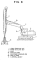
- FIG. 8 is a schematic side elevational view showing a hydraulic excavator (working machine) to which a common multistage expansion arm is attached.
- the hydraulic excavator includes a lower traveling unit 1, an upper revolving unit 2 coupled for revolution to the lower traveling unit 1, a boom 3 mounted for swinging motion on the upper revolving unit 2, a multistage expansion arm (expansible arm) 4 mounted for swinging motion at a tip end of the boom 3 and having an expansion/contraction function, a clamshell bucket 5 mounted at a tip end of the multistage expansion arm 4, and so forth.
- a boom cylinder 3a is provided between the boom 3 and the upper revolving unit 2, and the boom 3 is driven to swing in response to an expansion/contraction movement of the boom cylinder 3a.
- an arm cylinder 4a is provided between the boom 3 and the multistage expansion arm 4, and the multistage expansion arm 4 is driven to swing in response to an expansion/contraction movement of the arm cylinder 4a.
- a cylinder 11 [refer to FIG. 9] is provided for the multistage expansion arm 4 and can expand and contract the multistage expansion arm 4.
- the clamshell bucket 5 is configured for opening and closing movement by causing a hydraulic cylinder 5a [refer to FIG. 9] provided in the inside thereof to operate.
- FIG. 9 is a schematic view showing a general configuration of a hydraulic circuit for the hydraulic excavator described above. It is to be noted that a pilot circuit is not shown in FIG. 9.
- reference numeral 6 denotes a prime mover
- reference characters 7a, 7b denote each a hydraulic pump (pressure source) driven by the prime mover 6
- reference numeral 8 denotes a control valve unit for controlling pressure oil (operating oil) from the hydraulic pumps 7a, 7b to distribute the flow rates of the pressure oil to various actuators which are hereinafter described.
- Reference numeral 9 denotes a revolving motor for driving the revolving motor
- reference characters 10a, 10b denote each a traveling motor for driving a traveling apparatus not shown provided on the lower traveling unit 1.
- Reference character boom cylinder 3a denotes a boom cylinder, 4a an arm cylinder, 5a a bucket cylinder for opening and closing the clamshell bucket, 11 a telescopic cylinder for expanding and contracting the multistage expansion arm 4, 12 a slow return valve provided in a rod side chamber 11b of the telescopic cylinder 11, and 17 a tank.
- a restrictor is formed in the inside of the slow return valve 12 and prevents sudden expansion of the multistage expansion arm 4 by its own weight.
- Reference numeral 13 denotes a telescopic control valve for expanding or contracting the telescopic cylinder 11 built in the control valve unit 8, 14 a bucket control valve for operating the bucket cylinder 5a
- reference characters 15a, 15b denote each a telescopic remote control valve for controlling the telescopic control valve 13
- reference numeral 15 denotes a telescopic remote control lever for controlling movement of the telescopic remote control valves 15a, 15b
- valves 16a, 16b are bucket remote control valves for controlling the bucket control valve 14
- reference numeral 16 denotes a bucket remote control valve for controlling operation of the bucket remote control valves 16a, 16b.
- the telescopic remote control valve 15a is a remote control valve (opening operator) for expanding the telescopic cylinder 11, and when the telescopic remote control lever 15 is tilted rightwardly in the figure, the telescopic remote control valve 15a is opened and a pilot pressure corresponding to the operation amount of the telescopic remote control lever 15 is outputted.
- the bucket remote control valve 16a is a remote control valve (opening operator) for causing the clamshell bucket 5 to perform an opening movement, and when the bucket remote control lever 16 is tilted rightwardly in the figure, the bucket remote control valve 16a is opened and a pilot pressure corresponding to the operation amount of the bucket remote control lever 16 is outputted.
- Reference characters 103a, 104a, 109, 110a, 110b denote control valves for controlling movement of the boom cylinder 3a, arm cylinder 4a, revolving motor 9, and traveling motors 10a, 10b, respectively, and reference numeral 120 denotes a traveling straightforward valve for keeping straightforward traveling of the hydraulic excavator. It is to be noted that detailed description of the valves just mentioned is omitted.
- a pilot pressure acts upon a pilot port 13a to change over the telescopic control valve 13 of the control valve unit 8 from a chamber N to another chamber X. Then, pressure oil is supplied from the hydraulic pumps 7a, 7b into a head side chamber 11a of the telescopic cylinder 11 while pressure oil in the rod side chamber 11b is introduced into the tank 17 through the slow return valve 12 and the telescopic control valve 13.
- the present invention has been made in view of such a subject as just described, and it is an object of the present invention to provide a hydraulic circuit for a working machine which prevents drop of the working speed of a clamshell bucket upon expansion of an expansion arm so that improvement in operability is achieved.
- a hydraulic circuit for a working machine which includes an expansion arm and a clamshell bucket attached to a tip end of the expansion arm and is configured such that the expansion arm and the clamshell bucket are operated by pressure oil supplied from a common pressure source is characterized in that it comprises pressure reduction means for reducing an operating pressure for driving the expansion arm to the expansion side based on an operating pressure for opening the clamshell bucket.
- the pressure reduction means includes first pressure reduction means for reducing the operating pressure for opening the clamshell bucket and outputting the reduced operating pressure, and second pressure reduction means for reducing the operating pressure for driving the expansion arm to the expansion side based on the output pressure from the first pressure reduction means.
- the pressure reduction means includes operating pressure detection means for detecting the operating pressure for opening the clamshell bucket, and third pressure reduction means for reducing the operating pressure for driving the expansion arm to the expansion side based on detection information from the operating pressure detection means.
- the third pressure reduction means is set so that, as the operating pressure detected by the operating pressure detection means increases, the operating pressure for driving the expansion arm to the expansion side is reduced as much.
- a hydraulic circuit for a working machine which includes an expansion arm and a clamshell bucket attached to a tip end of the expansion arm is characterized in that it comprises a regeneration valve interposed between a working cylinder of the expansion arm and an output pressure supply path of the opening side of the clamshell bucket, when the expansion arm is driven to the expansion side, and capable of supplying returning pressure oil from the working cylinder to the output pressure supply path, and a directional control valve for being changed over, in response to an operating pressure for driving the expansion arm to the expansion side, so that an opening operating pressure for opening the clamshell bucket is supplied as a driving operating pressure for the regeneration valve to the regeneration valve to change over a working condition of the regeneration valve.
- the opening speed of the clamshell bucket can be increased without decreasing the expansion speed of the expansion arm. Consequently, there is another advantage that the subject, that the opening speed of the clamshell bucket is low, can be solved and improvement in operability can be achieved.
- the directional control valve has a non-response zone within which the driving operating pressure is not supplied to the regeneration valve within a region within which the operating pressure for driving the expansion arm to the expansion side is lower than a predetermined pressure.
- the expansion arm can be prevented from being expanded suddenly.
- the directional control valve is set such that, in another region wherein the operating pressure for driving the expansion arm is higher than the predetermined pressure, the driving operating pressure to be supplied to the regeneration valve increases in response to an increase of the operating pressure for driving the expansion arm to the expansion side.
- the regeneration valve may be configured such that, as the driving operating pressure supplied from the directional control valve increases, the amount of returning pressure oil to be supplied from the working cylinder to the output pressure supply path increases. Where the regeneration valve is configured in this manner, sudden expansion of the expansion arm within the region, wherein the driving operating pressure is low, is prevented, and in the region wherein the driving operating pressure is high, the clamshell bucket can be opened rapidly.
- a hydraulic circuit for a working machine which includes an expansion arm and a clamshell bucket attached to a tip end of the expansion arm is characterized in that it comprises a regeneration valve interposed between a working cylinder of the expansion arm and an output pressure supply path of the opening side of the clamshell bucket, and capable of supplying returning pressure oil from the working cylinder when the expansion arm is driven to the expansion side to the output pressure supply path, and that the working condition of the regeneration valve is controlled based on an operating pressure for driving the expansion arm to the expansion side.
- FIG. 1 is a schematic view showing a general configuration of the hydraulic circuit.
- the basic configuration of the apparatus is similar to that of the hydraulic circuit shown in FIG. 9, and elements described with reference to FIG. 9 are denoted by like reference characters and description of them is omitted.
- the hydraulic circuit of the first embodiment includes, as shown in FIG. 1, in addition to the general configuration shown in FIG. 9, a pressure reducing valve (first pressure reduction means) 20 for reducing the pilot pressure (operating pressure) from the bucket remote control valve (opening operator) 16a, and an external pilot type pressure reducing valve (second pressure reduction means) 21 provided for a pilot circuit on the expansion side of the telescopic cylinder (working cylinder) 11.
- the external pilot type pressure reducing valve 21 has a set pressure controlled in accordance with an output pressure of the pressure reducing valve 20, and when the output pressure of the pressure reducing valve 20 is lowest (for example, when the bucket remote control lever 16 is not operated), the output pressure from the telescopic remote control valve 15a is set to a high pressure without pressure reduction. On the other hand, if the bucket remote control valve 16a is operated by the bucket remote control lever 16 and the output pressure of the pressure reducing valve 20 is increased, then the operation of the external pilot type pressure reducing valve 21 is controlled in accordance with the pressure to reduce the pilot pressure of the remote control valve 15a.
- the hydraulic circuit for a working machine is configured in such a manner as described above, it operates in the following manner. It is to be noted that the following description is given separately of operation of the hydraulic circuit when the telescopic cylinder 11 operates by itself and operation when the telescopic cylinder 11 and the bucket cylinder 5a operate in an interlocking relationship.
- the telescopic remote control lever 15 is operated to open the telescopic remote control valve 15a, then the pilot pressure (operating pressure) is introduced to the pilot port 13a of the telescopic control valve 13 through a pipe L1 and the external pilot type pressure reducing valve 21, and the telescopic control valve 13 is changed over from the chamber N to the chamber X. Consequently, pressure oil in the hydraulic pumps (pressure source) 7a, 7b is supplied into the head side chamber 11a of the telescopic cylinder 11.
- pressure oil in the rod side chamber 11b of the telescopic cylinder 11 is introduced into the tank 17 through the slow return valve 12 and the chamber X of the telescopic control valve 13 to expand the telescopic cylinder 11.
- the bucket remote control lever 16 is not operated, then the output pressure of the pressure reducing valve 20 becomes the lowest pressure, and the external pilot type pressure reducing valve 21 is set to the highest pressure. Accordingly, the pilot pressure of the telescopic remote control valve 15a is introduced to the pilot port 13a of the telescopic control valve 13 without being reduced to fully open the valve 13, and consequently, the full flow amounts of the hydraulic pumps 7a, 7b are supplied into the head side chamber 11a of the telescopic cylinder 11 so that the telescopic cylinder 11 can be expanded at the highest speed.
- the hydraulic circuits for the telescopic cylinder 11 for the multistage expansion arm (expansion arm) 4 and the cylinder 5a for the clamshell bucket 5 are connected in parallel, and if the bucket cylinder 5a is operated simultaneously with an operation of the telescopic cylinder 11 to the expansion side, then pressure oil tends to flow only into the telescopic cylinder 11 whose pressure is lower.
- the present embodiment operates in the following manner.
- the bucket remote control valve 16a operates when the bucket remote control valve 16a is operated, then the pilot pressure is introduced to a pilot port 14a of the bucket control valve 14 through a pipe L2 so that the bucket control valve 14 is changed over from the chamber N to the chamber X and the pilot pressure is introduced also into the pressure reducing valve 20.
- the pilot pressure of the bucket remote control valve 16a is reduced (controlled to a pressure within a prescribed pressure) by the pressure reducing valve 20 and outputted to a pilot port 21a of the external pilot type pressure reducing valve 21. Consequently, as the operation amount of the bucket remote control valve 16a increases, the set pressure of the external pilot type pressure reducing valve 21 drops from the highest pressure to the prescribed pressure.
- the pilot pressure of the telescopic remote control valve 15a is reduced by the external pilot type pressure reducing valve 21 so that the pilot pressure of the telescopic control valve 13 is controlled so as not to increase equal to or greater than the prescribed pressure.
- the stroke of the telescopic control valve 13 is limited to a predetermined stroke by the reduced pilot pressure, and the opening area of the telescopic control valve 13, interposed between the hydraulic pumps 7a, 7b and the telescopic cylinder 11, is restricted to increase the pump pressure. Consequently, the expansion speed of the telescopic cylinder 11 decreases and the supply flow rate from the bucket control valve 14 to the bucket cylinder 5a increases, thereby increasing the opening speed of the clamshell bucket 5.
- FIG. 2 is a schematic view showing a general configuration of the hydraulic circuit
- FIG. 3 is a schematic block diagram showing a configuration of control means of the hydraulic circuit.
- the present second embodiment has a basic configuration similar to that of the hydraulic circuit shown in FIG. 9 and includes, as shown in FIG. 2, in addition to the configuration shown in FIG. 9, a pressure detector (operating pressure detection means) 22 provided at the output port of the bucket remote control valve (opening operator) 16a, a solenoid controlled proportional pressure reducing valve (third pressure reduction means) 23 provided between the telescopic remote control valve 15a and the pilot port 13a of the telescopic control valve 13, and a controller (control means) 24 for outputting a driving signal to the solenoid controlled proportional pressure reducing valve 23 based on a signal of the pressure detector 22.
- a pressure detector operating pressure detection means
- a solenoid controlled proportional pressure reducing valve third pressure reduction means 23 provided between the telescopic remote control valve 15a and the pilot port 13a of the telescopic control valve 13
- controller controller
- a pressure setter 25, for outputting a set pressure of the solenoid controlled proportional pressure reducing valve 23 based on a signal of the pressure detector 22, and a solenoid valve driver 26, for outputting driving current for the solenoid controlled proportional pressure reducing valve 23 based on a set pressure signal outputted from the pressure setter 25, are provided in the controller 24.
- the pressure setter 25 is basically set so that, when the pilot pressure (operating pressure) of the bucket remote control valve 16a is low, the set pressure of the solenoid controlled proportional pressure reducing valve 23 is high.
- FIG. 3 illustrates an example of characteristic of the pressure setter 25.
- the set pressure of the solenoid controlled proportional pressure reducing valve 23 decreases linearly in response to an increase of the pilot pressure of the remote control valve 16a. Further, where the pilot pressure is equal to or smaller than the range, the set pressure is fixed to the highest value therefor, but where the pilot pressure is equal to or greater than the range, the set pressure is fixed to the lowest value therefor.
- the hydraulic circuit for a working machine according to the second embodiment of the present invention is configured in such a manner as described above, and operation of the hydraulic circuit is described below separately for a case wherein the telescopic cylinder 11 operates by itself and another case wherein the telescopic cylinder 11 and the bucket cylinder 5a operate in an interlocking relationship.
- the pressure setter 25 outputs a signal to make the pilot pressure of the bucket remote control valve 16a the highest pressure, and the solenoid controlled proportional pressure reducing valve 23 is driven through the solenoid valve driver 26.
- the pilot pressure of the telescopic remote control valve 15a is outputted, for example, as it is without being reduced and is introduced to the pilot port 13a of the telescopic control valve 13.
- the full flow amounts of the hydraulic pumps 7a, 7b are supplied to the telescopic cylinder 11 through the telescopic control valve 13, and consequently, the telescopic cylinder 11 can be expanded at the highest speed.
- the pilot pressure of the bucket remote control valve 16a is detected by the pressure detector 22, and a control signal for the solenoid controlled proportional pressure reducing valve 23 is set by the pressure setter 25.
- the pilot pressure of the telescopic remote control valve 15a is limited to the prescribed pressure by the solenoid controlled proportional pressure reducing valve 23, and the reduced pilot pressure is outputted to the pilot port 13a of the telescopic control valve 13.
- the stroke of the telescopic control valve 13 is limited to a predetermined stroke corresponding to the reduced pilot pressure, and consequently, the opening area of the telescopic control valve 13 interposed between the hydraulic pumps 7a, 7b and the telescopic cylinder 11 is restricted to increase the pump pressure. Accordingly, the supply flow rate of operating oil from the bucket control valve 14 to the bucket cylinder 5a increases, thereby increasing the opening speed of the clamshell bucket 5.
- the hydraulic circuit may be configured otherwise such that a plurality of characteristic of the pressure setter 25 of the controller 24 are stored in a memory not shown and the characteristic of the pressure setter 25 is suitably changed in accordance with the working situation or the attached clamshell bucket or the like.
- the hydraulic circuit is advantageous in that, when the bucket 5 of a different weight is attached, or the different cylinder 11 is attached, adjustment of the speed can be performed more readily than that in the first embodiment and operation adjustment is simplified.
- the characteristic of the pressure setter 25 is not limited to that illustrated in FIG. 3, but can be set to various other characteristic only if the pressure setter 25 has such a characteristic that the set pressure of the solenoid controlled proportional pressure reducing valve 23 is reduced in response to an increase of the pilot pressure of the telescopic remote control valve 16a.
- FIG. 4 is a schematic view showing a general configuration of the hydraulic circuit
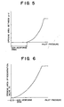
- FIGS. 5 and 6 are diagrams illustrating different control characteristic of the hydraulic circuit.
- hydraulic circuit of the present third embodiment has a basic configuration similar to that of the hydraulic circuit shown in FIG. 9, and elements described hereinabove with reference to FIG. 9 are denoted by like reference characters and description of them is omitted.
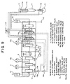
- the hydraulic circuit includes, as shown in FIG. 4, in addition to the configuration shown in FIG. 9, a regeneration valve 30 for introducing pressure oil of the rod side chamber 11b of the telescopic cylinder (working cylinder) 11 into an output pressure supply path s between the bucket control valve 14 and the pump 7b, a confluence check valve 31 interposed between the regeneration valve 30 and the bucket control valve 14, and a directional control valve 32 which is controlled to change over by the pilot pressure (operating pressure) of the telescopic remote control valve 15a.
- a regeneration valve 30 for introducing pressure oil of the rod side chamber 11b of the telescopic cylinder (working cylinder) 11 into an output pressure supply path s between the bucket control valve 14 and the pump 7b
- a confluence check valve 31 interposed between the regeneration valve 30 and the bucket control valve 14
- a directional control valve 32 which is controlled to change over by the pilot pressure (operating pressure) of the telescopic remote control valve 15a.
- the pilot pressure of the bucket remote control valve 16a is introduced to an input port p of the directional control valve 32, and an output port d is connected to a pilot port 30a of the regeneration valve 30.
- the operation condition of the directional control valve 32 is controlled based on the pilot pressure when the telescopic cylinder 11 is driven to the expansion side, and the operation condition of the regeneration valve 30 is controlled in response to the operation condition of the directional control valve 32.
- the operating oil (returning pressure oil) in the rod side chamber 11b of the telescopic cylinder 11 is supplied to the output pressure supply path s.
- the hydraulic circuit for a working machine according to the third embodiment of the present invention is configured in such a manner as described above, and operation of the hydraulic circuit is described below separately for a case wherein the telescopic cylinder 11 operates by itself and another case wherein the telescopic cylinder 11 and the bucket cylinder 5a operate in an interlocking relationship.
- the pilot pressure of the telescopic remote control valve 15a is introduced to the pilot port 13a of the telescopic control valve 13 through the pipe L1, and the telescopic control valve 13 is changed over from the chamber N to the chamber X. Further, the pilot pressure is supplied also to a pilot port 32a of the directional control valve 32 so that the directional control valve 32 is changed over from a chamber C to another chamber A.
- the pilot pressure of the remote control valve 16a is introduced into the pilot port 30a of the regeneration valve 30 through the pipe L2 and the chamber A of the directional control valve 32 and functions as a pilot pressure (driving operating pressure) for the regeneration valve 30, and the regeneration valve 30 is changed over from the chamber C to the chamber A.
- the rod side chamber 11b of the telescopic cylinder 11 and the bucket control valve 14 are connected to each other. Meanwhile, since a high pressure is generated in the rod side chamber 11b by the weights of the multistage expansion arm 4 and the clamshell bucket 5 themselves, part of the pressure oil (returning oil) of the rod side chamber 11b is supplied to the bucket control valve 14 through the regeneration valve 30, confluence check valve 31 and output pressure supply path s.
- the opening characteristic from the port p to the port d of the directional control valve 32 is set, for example, in such a manner as illustrated in FIG. 5.
- the opening characteristic is set such that a region (non-response zone) wherein the port p and the port d are completely disconnected, when the pilot pressure of the telescopic remote control valve 15a is low, is provided and, when the pilot pressure increases, the opening area increases moderately in response to the increase of the pilot pressure.
- FIG. 5 exhibits such a characteristic that the opening area increases in a quadratic curve as the pilot pressure increases
- the characteristic of the directional control valve 32 is not limited to that illustrated in FIG. 5, but may be any other characteristic if the characteristic is such that, at least when the pilot pressure becomes equal to or greater than a predetermined value, the opening area increases gradually in response an increase of the pilot pressure.
- the characteristic of the regeneration valve 30 is set, for example, in such a manner as illustrated in FIG. 6.
- the characteristic of the regeneration valve 30 is set so that, when the pilot pressure of the bucket remote control valve 16a (the driving operating pressure acting upon the pilot port 30a) increases, the opening area of the regeneration valve 30 gradually increases accordingly.
- the characteristic of the regeneration valve 30 is not limited to that shown in FIG. 6 but may be modified in various manners as described hereinabove with reference to FIG. 5. Further, while, in the example illustrated in FIG. 6, a region (non-response zone) wherein the opening area of the regeneration valve 30 is zero, is provided within a range within which the pilot pressure is very low, such a non-response zone as just described need not be provided depending upon adjustment of the other design items.
- the variations in speed of the bucket cylinder 5a and the telescopic cylinder 11 can be moderated.
- pressure oil of the telescopic cylinder 11 is supplied into the bucket cylinder 5a, it is not necessary to limit the pilot pressure of the telescopic control valve 13 to restrict the telescopic control valve 13 as in the first and second embodiments described hereinabove, and consequently, there is no necessity to increase the pump pressure to a level greater than a necessary level. Consequently, the hydraulic circuit is advantageous also in that energy saving can be anticipated and the operation efficiency can be improved.
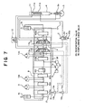
- FIG. 7 is a schematic view showing a general configuration of the hydraulic circuit. Also the hydraulic circuit of the present fourth embodiment has a basic configuration similar to that of the hydraulic circuit shown in FIG. 9, and elements described with reference to FIG. 9 are denoted by like reference characters and description of them is omitted.
- the hydraulic circuit in the fourth embodiment includes, as shown in FIG. 7, in addition to the configuration shown in FIG. 9, a regeneration valve 35 for merging pressure oil of the rod side chamber 11b of the telescopic cylinder 11 with the delivery side of the hydraulic pump 7b, and a confluence check valve 36 provided between the regeneration valve 35 and the delivery port of the hydraulic pump 7b.
- a regeneration valve 35 for merging pressure oil of the rod side chamber 11b of the telescopic cylinder 11 with the delivery side of the hydraulic pump 7b
- a confluence check valve 36 provided between the regeneration valve 35 and the delivery port of the hydraulic pump 7b.
- the regeneration valve 35 is a directional control valve which normally disconnects the rod side chamber 11b and the delivery side of the hydraulic pump 7b from each other, but connects them to each other if a pilot pressure is supplied thereto, and a restrictor (orifice) is formed in the communication path.
- the pilot pressure supply pipe L1 of the telescopic remote control valve 15a is connected to a pilot port 35a of the regeneration valve 35.
- the hydraulic circuit for a working machine according to the fourth embodiment of the present invention is configured in such a manner as described above, and operation of the hydraulic circuit is described below separately for a case wherein the telescopic cylinder 11 operates by itself and another case wherein the telescopic cylinder 11 and the bucket cylinder 5a operate in an interlocking relationship.
- the pilot pressure from the telescopic remote control valve 15a is supplied to the pilot port 13a of the telescopic control valve 13 through the pipe L1, and the telescopic control valve 13 is changed over from the chamber N to the chamber X.
- the pilot pressure is introduced also to the pilot port 35a of the regeneration valve 35 so that the regeneration valve 35 is changed over from a chamber C to a chamber A. Consequently, the rod side chamber 11b of the telescopic cylinder 11 and the delivery side of the pump 7b are connected to each other through the regeneration valve 35.
- pressure oil from the hydraulic pumps 7a, 7b is supplied through the telescopic control valve 13 to the head side chamber 11a of the telescopic cylinder 11. Meanwhile, part of pressure oil in the rod side chamber 11b of the telescopic cylinder 11 is introduced into the tank 17 through the slow return valve 12 and the chamber X of the telescopic control valve 13 while the remaining pressure oil is merged with delivered pressure oil of the pump 7b through the regeneration valve 35 and the confluence check valve 36 and supplied into the control valve unit 8. Accordingly, since the pressure oil supplied to the head side chamber 11a of the telescopic cylinder 11 becomes greater than that of the hydraulic circuit shown in FIG. 9, the telescopic cylinder 11 can be expanded at a higher speed.
- the pilot pressure of the bucket remote control valve 16a is introduced to the pilot port 14a of the bucket control valve 14 so that the bucket control valve 14 is changed over from the chamber N to the chamber X. Since a high pressure is generated in the rod side chamber 11b of the telescopic cylinder 11 by the weights of the multistage expansion arm 4 and the clamshell bucket 5 themselves, part of the pressure oil is supplied to the delivery side of the hydraulic pump 7b through the regeneration valve 35 and the confluence check valve 36, and consequently, the pump pressure becomes comparatively high.
- the hydraulic circuit of the present embodiment is advantageous in that the expansion speed of the telescopic cylinder 11 can be increased when compared with those of the hydraulic circuits of the embodiments described hereinabove.
- the speed of the telescopic cylinder 11 decreases when the operation for expanding the multistage expansion arm 4 and the operation for opening the clamshell bucket 5 are performed in an interlocking relationship
- the expansion speed of the telescopic cylinder 11 can be assured and the opening/closing speed of the clamshell bucket 5 can be increased.
- the hydraulic circuit of the present embodiment is advantageous in that the working speed can be increased and the subject that the opening speed of the clamshell bucket 5 is low can be eliminated and improvement in operability and working efficiency can be achieved.
- the hydraulic circuit for a working machine of the present invention is not limited to those of the embodiments described above and various modifications are possible without departing from the spirit of the present invention.
- the configuration of details and the control characteristic of the hydraulic circuit can be altered suitably in accordance with a change in design conditions, specifications of a model or the like.
- the hydraulic circuit for a working machine of the present invention is useful as a hydraulic circuit applied particularly to a working machine based on a hydraulic excavator and having a multistage expansion arm for caisson type excavation.
Abstract
Description
- This invention relates to a hydraulic circuit for a working machine such as a hydraulic excavator, and more particularly to a hydraulic circuit for a working machine suitable for use with a working machine based on a hydraulic excavator and having a multistage expansion arm for caisson type excavation.
- FIG. 8 is a schematic side elevational view showing a hydraulic excavator (working machine) to which a common multistage expansion arm is attached. The hydraulic excavator includes a
lower traveling unit 1, an upper revolvingunit 2 coupled for revolution to thelower traveling unit 1, aboom 3 mounted for swinging motion on the upper revolvingunit 2, a multistage expansion arm (expansible arm) 4 mounted for swinging motion at a tip end of theboom 3 and having an expansion/contraction function, aclamshell bucket 5 mounted at a tip end of themultistage expansion arm 4, and so forth. - A
boom cylinder 3a is provided between theboom 3 and the upper revolvingunit 2, and theboom 3 is driven to swing in response to an expansion/contraction movement of theboom cylinder 3a. Similarly, anarm cylinder 4a is provided between theboom 3 and themultistage expansion arm 4, and themultistage expansion arm 4 is driven to swing in response to an expansion/contraction movement of thearm cylinder 4a. It is to be noted that a cylinder 11 [refer to FIG. 9] is provided for themultistage expansion arm 4 and can expand and contract themultistage expansion arm 4. - The
clamshell bucket 5 is configured for opening and closing movement by causing ahydraulic cylinder 5a [refer to FIG. 9] provided in the inside thereof to operate. - FIG. 9 is a schematic view showing a general configuration of a hydraulic circuit for the hydraulic excavator described above. It is to be noted that a pilot circuit is not shown in FIG. 9. Referring to FIG. 9,
reference numeral 6 denotes a prime mover,reference characters prime mover 6, andreference numeral 8 denotes a control valve unit for controlling pressure oil (operating oil) from thehydraulic pumps Reference numeral 9 denotes a revolving motor for driving the revolvingmotor 9, andreference characters lower traveling unit 1. - Reference
character boom cylinder 3a denotes a boom cylinder, 4a an arm cylinder, 5a a bucket cylinder for opening and closing the clamshell bucket, 11 a telescopic cylinder for expanding and contracting themultistage expansion arm 4, 12 a slow return valve provided in arod side chamber 11b of thetelescopic cylinder 11, and 17 a tank. - When operating oil is supplied into a hydraulic chamber at an upper portion in the figure of the
bucket cylinder 5a to move thebucket cylinder 5a downwardly in the figure, theclamshell bucket 5 is opened. A restrictor (orifice) is formed in the inside of theslow return valve 12 and prevents sudden expansion of themultistage expansion arm 4 by its own weight. -
Reference numeral 13 denotes a telescopic control valve for expanding or contracting thetelescopic cylinder 11 built in thecontrol valve unit bucket cylinder 5a,reference characters telescopic control valve 13,reference numeral 15 denotes a telescopic remote control lever for controlling movement of the telescopicremote control valves valves bucket control valve 14, and reference numeral 16 denotes a bucket remote control valve for controlling operation of the bucketremote control valves - Of the components given above, the telescopic
remote control valve 15a is a remote control valve (opening operator) for expanding thetelescopic cylinder 11, and when the telescopicremote control lever 15 is tilted rightwardly in the figure, the telescopicremote control valve 15a is opened and a pilot pressure corresponding to the operation amount of the telescopicremote control lever 15 is outputted. - The bucket
remote control valve 16a is a remote control valve (opening operator) for causing theclamshell bucket 5 to perform an opening movement, and when the bucket remote control lever 16 is tilted rightwardly in the figure, the bucketremote control valve 16a is opened and a pilot pressure corresponding to the operation amount of the bucket remote control lever 16 is outputted. -
Reference characters boom cylinder 3a,arm cylinder 4a, revolvingmotor 9, and travelingmotors reference numeral 120 denotes a traveling straightforward valve for keeping straightforward traveling of the hydraulic excavator. It is to be noted that detailed description of the valves just mentioned is omitted. - Referring to FIG. 9, if the telescopic
remote control lever 15 is operated to open the telescopicremote control valve 15a, then a pilot pressure acts upon apilot port 13a to change over thetelescopic control valve 13 of thecontrol valve unit 8 from a chamber N to another chamber X. Then, pressure oil is supplied from thehydraulic pumps head side chamber 11a of thetelescopic cylinder 11 while pressure oil in therod side chamber 11b is introduced into thetank 17 through theslow return valve 12 and thetelescopic control valve 13. - At this time, since the weights of the
multistage expansion arm 4 and theclamshell bucket 5 themselves act in therod side chamber 11b of thetelescopic cylinder 11, a high pressure is generated in therod side chamber 11b, but the pressure in thehead side chamber 11a becomes low since no load is applied to thehead side chamber 11a. - Accordingly, if the bucket remote control lever 16 is operated in order to open the
clamshell bucket 5 while themultistage expansion arm 4 is being extended, then most of pressure oil in thehydraulic pumps head side chamber 11a of thetelescopic cylinder 11 which has a lower working pressure. Consequently, sufficient pressure oil is not supplied into thebucket cylinder 5a and the speed at which theclamshell bucket 5 is opened is reduced, resulting in a subject that the operability is deteriorated. - The present invention has been made in view of such a subject as just described, and it is an object of the present invention to provide a hydraulic circuit for a working machine which prevents drop of the working speed of a clamshell bucket upon expansion of an expansion arm so that improvement in operability is achieved.
- In order to attain the object described above, according to an aspect of the present invention, a hydraulic circuit for a working machine which includes an expansion arm and a clamshell bucket attached to a tip end of the expansion arm and is configured such that the expansion arm and the clamshell bucket are operated by pressure oil supplied from a common pressure source is characterized in that it comprises pressure reduction means for reducing an operating pressure for driving the expansion arm to the expansion side based on an operating pressure for opening the clamshell bucket.
- Accordingly, with the hydraulic circuit for a working machine of the present invention, when an operation for opening the clamshell bucket is performed while the expansion arm is being expanded by reducing the operating pressure for driving the expansion arm to the expansion side based on the operating pressure for opening the clamshell bucket, supply of pressure oil for driving the expansion arm to the expansion side is limited so that the supply amount of pressure oil to the clamshell bucket can be increased as much. Consequently, the clamshell bucket can be opened rapidly, and the subject that the speed at which the clamshell bucket is opened is low can be solved and improvement of the operability can be achieved.
- Preferably, the pressure reduction means includes first pressure reduction means for reducing the operating pressure for opening the clamshell bucket and outputting the reduced operating pressure, and second pressure reduction means for reducing the operating pressure for driving the expansion arm to the expansion side based on the output pressure from the first pressure reduction means.
- By the configuration, similar advantages to those described above can be achieved. Further, there is an another advantage that the present apparatus can be provided readily at a low cost.
- Preferably, the pressure reduction means includes operating pressure detection means for detecting the operating pressure for opening the clamshell bucket, and third pressure reduction means for reducing the operating pressure for driving the expansion arm to the expansion side based on detection information from the operating pressure detection means.
- By the configuration, similar advantages to those described above can be achieved. Further, since it is necessary to add only one pressure reduction means as a hydraulic apparatus to a common hydraulic circuit, there is an another advantage that the present apparatus can be provided readily at a low cost similarly.
- It is to be noted that, in this instance, further preferably the third pressure reduction means is set so that, as the operating pressure detected by the operating pressure detection means increases, the operating pressure for driving the expansion arm to the expansion side is reduced as much.
- According to another aspect of the present invention, a hydraulic circuit for a working machine which includes an expansion arm and a clamshell bucket attached to a tip end of the expansion arm is characterized in that it comprises a regeneration valve interposed between a working cylinder of the expansion arm and an output pressure supply path of the opening side of the clamshell bucket, when the expansion arm is driven to the expansion side, and capable of supplying returning pressure oil from the working cylinder to the output pressure supply path, and a directional control valve for being changed over, in response to an operating pressure for driving the expansion arm to the expansion side, so that an opening operating pressure for opening the clamshell bucket is supplied as a driving operating pressure for the regeneration valve to the regeneration valve to change over a working condition of the regeneration valve.
- Accordingly, there is an advantage that, when the operation for expanding the expansion arm and the operation for opening the clamshell bucket are performed in an interlocking relationship, the opening speed of the clamshell bucket can be increased without decreasing the expansion speed of the expansion arm. Consequently, there is another advantage that the subject, that the opening speed of the clamshell bucket is low, can be solved and improvement in operability can be achieved.
- Preferably, the directional control valve has a non-response zone within which the driving operating pressure is not supplied to the regeneration valve within a region within which the operating pressure for driving the expansion arm to the expansion side is lower than a predetermined pressure. By such configuration, the expansion arm can be prevented from being expanded suddenly.
- Further preferably, the directional control valve is set such that, in another region wherein the operating pressure for driving the expansion arm is higher than the predetermined pressure, the driving operating pressure to be supplied to the regeneration valve increases in response to an increase of the operating pressure for driving the expansion arm to the expansion side. By such configuration, as the operating pressure for expanding the expansion arm increases, the clamshell bucket can be opened at a higher speed.
- The regeneration valve may be configured such that, as the driving operating pressure supplied from the directional control valve increases, the amount of returning pressure oil to be supplied from the working cylinder to the output pressure supply path increases. Where the regeneration valve is configured in this manner, sudden expansion of the expansion arm within the region, wherein the driving operating pressure is low, is prevented, and in the region wherein the driving operating pressure is high, the clamshell bucket can be opened rapidly.
- According to a further aspect of the present invention, a hydraulic circuit for a working machine which includes an expansion arm and a clamshell bucket attached to a tip end of the expansion arm is characterized in that it comprises a regeneration valve interposed between a working cylinder of the expansion arm and an output pressure supply path of the opening side of the clamshell bucket, and capable of supplying returning pressure oil from the working cylinder when the expansion arm is driven to the expansion side to the output pressure supply path, and that the working condition of the regeneration valve is controlled based on an operating pressure for driving the expansion arm to the expansion side.
- Accordingly, by controlling the working condition of the regeneration valve based on the operating pressure for driving the expansion arm to the expansion side, there is an advantage that, when the operation for expanding the expansion arm and the operation for opening the clamshell bucket are performed in an interlocking relationship, the opening speed of the clamshell bucket can be increased without decreasing the expansion speed of the expansion arm.
- Consequently, there is another advantage that the subject that the opening speed of the clamshell bucket is low can be solved and improvement in operability can be achieved.
-
- FIG. 1 is a schematic view showing a general configuration of a hydraulic circuit for a working machine according to a first embodiment of the present invention;
- FIG. 2 is a schematic view showing a general configuration of a hydraulic circuit for a working machine according to a second embodiment of the present invention;
- FIG. 3 is a schematic block diagram showing a configuration of control means of the hydraulic circuit for a working machine according to the second embodiment of the present invention;
- FIG. 4 is a schematic view showing a general configuration of a hydraulic circuit for a working machine according to a third embodiment of the present invention;
- FIG. 5 is a diagram illustrating a control characteristic of the hydraulic circuit for a working machine according to the third embodiment of the present invention;
- FIG. 6 is a diagram illustrating another control characteristic of the hydraulic circuit for a working machine according to the third embodiment of the present invention;
- FIG. 7 is a schematic view showing a general configuration of a hydraulic circuit for a working machine according to a fourth embodiment of the present invention;
- FIG. 8 is a schematic side elevational view showing a hydraulic excavator to which a common multistage expansion arm is attached; and
- FIG. 9 is a schematic view showing a general configuration of a hydraulic circuit for a hydraulic excavator to which a common multistage expansion arm is attached.
-
- In the following, embodiments of the present invention are described with reference to the drawings.
- First, a hydraulic circuit for a working machine according to a first embodiment of the present invention is described. FIG. 1 is a schematic view showing a general configuration of the hydraulic circuit.
- In the hydraulic circuit of the first embodiment of the present invention, the basic configuration of the apparatus is similar to that of the hydraulic circuit shown in FIG. 9, and elements described with reference to FIG. 9 are denoted by like reference characters and description of them is omitted.
- The hydraulic circuit of the first embodiment includes, as shown in FIG. 1, in addition to the general configuration shown in FIG. 9, a pressure reducing valve ( first pressure reduction means) 20 for reducing the pilot pressure (operating pressure) from the bucket remote control valve (opening operator) 16a, and an external pilot type pressure reducing valve (second pressure reduction means) 21 provided for a pilot circuit on the expansion side of the telescopic cylinder (working cylinder) 11.
- The external pilot type
pressure reducing valve 21 has a set pressure controlled in accordance with an output pressure of thepressure reducing valve 20, and when the output pressure of thepressure reducing valve 20 is lowest (for example, when the bucket remote control lever 16 is not operated), the output pressure from the telescopicremote control valve 15a is set to a high pressure without pressure reduction. On the other hand, if the bucketremote control valve 16a is operated by the bucket remote control lever 16 and the output pressure of thepressure reducing valve 20 is increased, then the operation of the external pilot typepressure reducing valve 21 is controlled in accordance with the pressure to reduce the pilot pressure of theremote control valve 15a. - Then, if the output pressure of the
pressure reducing valve 20 becomes equal to or greater than a predetermined value, then the pilot pressure to thetelescopic control valve 13 does not become equal to or greater than a prescribed pressure. - Since the hydraulic circuit for a working machine according to the first embodiment of the present invention is configured in such a manner as described above, it operates in the following manner. It is to be noted that the following description is given separately of operation of the hydraulic circuit when the
telescopic cylinder 11 operates by itself and operation when thetelescopic cylinder 11 and thebucket cylinder 5a operate in an interlocking relationship. - Referring to FIG. 1, if the telescopic
remote control lever 15 is operated to open the telescopicremote control valve 15a, then the pilot pressure (operating pressure) is introduced to thepilot port 13a of thetelescopic control valve 13 through a pipe L1 and the external pilot typepressure reducing valve 21, and thetelescopic control valve 13 is changed over from the chamber N to the chamber X. Consequently, pressure oil in the hydraulic pumps (pressure source) 7a, 7b is supplied into thehead side chamber 11a of thetelescopic cylinder 11. - Meanwhile, pressure oil in the
rod side chamber 11b of thetelescopic cylinder 11 is introduced into thetank 17 through theslow return valve 12 and the chamber X of thetelescopic control valve 13 to expand thetelescopic cylinder 11. - At this time, if the bucket remote control lever 16 is not operated, then the output pressure of the
pressure reducing valve 20 becomes the lowest pressure, and the external pilot typepressure reducing valve 21 is set to the highest pressure. Accordingly, the pilot pressure of the telescopicremote control valve 15a is introduced to thepilot port 13a of thetelescopic control valve 13 without being reduced to fully open thevalve 13, and consequently, the full flow amounts of thehydraulic pumps head side chamber 11a of thetelescopic cylinder 11 so that thetelescopic cylinder 11 can be expanded at the highest speed. - As shown in FIG. 1, the hydraulic circuits for the
telescopic cylinder 11 for the multistage expansion arm (expansion arm) 4 and thecylinder 5a for theclamshell bucket 5 are connected in parallel, and if thebucket cylinder 5a is operated simultaneously with an operation of thetelescopic cylinder 11 to the expansion side, then pressure oil tends to flow only into thetelescopic cylinder 11 whose pressure is lower. In this instance, the present embodiment operates in the following manner. - Namely, if the bucket
remote control valve 16a operates when the bucketremote control valve 16a is operated, then the pilot pressure is introduced to apilot port 14a of thebucket control valve 14 through a pipe L2 so that thebucket control valve 14 is changed over from the chamber N to the chamber X and the pilot pressure is introduced also into thepressure reducing valve 20. - The pilot pressure of the bucket
remote control valve 16a is reduced (controlled to a pressure within a prescribed pressure) by thepressure reducing valve 20 and outputted to apilot port 21a of the external pilot typepressure reducing valve 21. Consequently, as the operation amount of the bucketremote control valve 16a increases, the set pressure of the external pilot typepressure reducing valve 21 drops from the highest pressure to the prescribed pressure. - Accordingly, upon the opening movement of the bucket
remote control valve 16a, the pilot pressure of the telescopicremote control valve 15a is reduced by the external pilot typepressure reducing valve 21 so that the pilot pressure of thetelescopic control valve 13 is controlled so as not to increase equal to or greater than the prescribed pressure. - As a result, the stroke of the
telescopic control valve 13 is limited to a predetermined stroke by the reduced pilot pressure, and the opening area of thetelescopic control valve 13, interposed between thehydraulic pumps telescopic cylinder 11, is restricted to increase the pump pressure. Consequently, the expansion speed of thetelescopic cylinder 11 decreases and the supply flow rate from thebucket control valve 14 to thebucket cylinder 5a increases, thereby increasing the opening speed of theclamshell bucket 5. - By the operation described above, when an operation for opening the
clamshell bucket 5 is performed while themultistage expansion arm 4 is being expanded, pressure oil can be supplied with certainty to theclamshell bucket 5 while limiting supply of pressure oil to thetelescopic cylinder 11, and therefore, theclamshell bucket 5 can be opened rapidly. Consequently, the subject described in the background art hereinabove that the speed at which theclamshell bucket 5 is opened is low can be solved and improvement of the operability can be achieved. Further, since only it is necessary to add the twopressure reducing valves - Now, a hydraulic circuit for a working machine according to a second embodiment of the present invention is described. FIG. 2 is a schematic view showing a general configuration of the hydraulic circuit, and FIG. 3 is a schematic block diagram showing a configuration of control means of the hydraulic circuit.
- The present second embodiment has a basic configuration similar to that of the hydraulic circuit shown in FIG. 9 and includes, as shown in FIG. 2, in addition to the configuration shown in FIG. 9, a pressure detector (operating pressure detection means) 22 provided at the output port of the bucket remote control valve (opening operator) 16a, a solenoid controlled proportional pressure reducing valve (third pressure reduction means) 23 provided between the telescopic
remote control valve 15a and thepilot port 13a of thetelescopic control valve 13, and a controller (control means) 24 for outputting a driving signal to the solenoid controlled proportionalpressure reducing valve 23 based on a signal of thepressure detector 22. It is to be noted that those elements described hereinabove with reference to FIG. 9 are denoted by like reference characters and description of them is omitted. - Further, as shown in FIG. 3, a
pressure setter 25, for outputting a set pressure of the solenoid controlled proportionalpressure reducing valve 23 based on a signal of thepressure detector 22, and asolenoid valve driver 26, for outputting driving current for the solenoid controlled proportionalpressure reducing valve 23 based on a set pressure signal outputted from thepressure setter 25, are provided in thecontroller 24. - Here, a characteristic of the
pressure setter 25 is described briefly. Thepressure setter 25 is basically set so that, when the pilot pressure (operating pressure) of the bucketremote control valve 16a is low, the set pressure of the solenoid controlled proportionalpressure reducing valve 23 is high. - FIG. 3 illustrates an example of characteristic of the
pressure setter 25. When the pilot pressure is within a certain range, the set pressure of the solenoid controlled proportionalpressure reducing valve 23 decreases linearly in response to an increase of the pilot pressure of theremote control valve 16a. Further, where the pilot pressure is equal to or smaller than the range, the set pressure is fixed to the highest value therefor, but where the pilot pressure is equal to or greater than the range, the set pressure is fixed to the lowest value therefor. - The hydraulic circuit for a working machine according to the second embodiment of the present invention is configured in such a manner as described above, and operation of the hydraulic circuit is described below separately for a case wherein the
telescopic cylinder 11 operates by itself and another case wherein thetelescopic cylinder 11 and thebucket cylinder 5a operate in an interlocking relationship. - First, if the telescopic
remote control valve 15a is opened while the bucket remote control lever 16 is not in an operation state (when the bucketremote control valve 16a is closed), then the pilot pressure from the telescopicremote control valve 15a is introduced to the solenoid controlled proportionalpressure reducing valve 23. - At this time, since the pilot pressure of the
remote control valve 16a detected by thepressure detector 22 has the lowest value, thepressure setter 25 outputs a signal to make the pilot pressure of the bucketremote control valve 16a the highest pressure, and the solenoid controlled proportionalpressure reducing valve 23 is driven through thesolenoid valve driver 26. - Consequently, the pilot pressure of the telescopic
remote control valve 15a is outputted, for example, as it is without being reduced and is introduced to thepilot port 13a of thetelescopic control valve 13. As a result, the full flow amounts of thehydraulic pumps telescopic cylinder 11 through thetelescopic control valve 13, and consequently, thetelescopic cylinder 11 can be expanded at the highest speed. - When the bucket
remote control valve 16a is opened, the pilot pressure of the bucketremote control valve 16a is detected by thepressure detector 22, and a control signal for the solenoid controlled proportionalpressure reducing valve 23 is set by thepressure setter 25. - Then, if the bucket
remote control valve 16a is operated to its fully open state, then the output of the solenoid controlled proportionalpressure reducing valve 23 is gradually decreased from the highest pressure to the prescribed pressure in response to an increase of the pilot pressure. - Accordingly, the pilot pressure of the telescopic
remote control valve 15a is limited to the prescribed pressure by the solenoid controlled proportionalpressure reducing valve 23, and the reduced pilot pressure is outputted to thepilot port 13a of thetelescopic control valve 13. - As a result, the stroke of the
telescopic control valve 13 is limited to a predetermined stroke corresponding to the reduced pilot pressure, and consequently, the opening area of thetelescopic control valve 13 interposed between thehydraulic pumps telescopic cylinder 11 is restricted to increase the pump pressure. Accordingly, the supply flow rate of operating oil from thebucket control valve 14 to thebucket cylinder 5a increases, thereby increasing the opening speed of theclamshell bucket 5. - By the operation described above, similarly as in the first embodiment described hereinabove, if an operation for opening the
clamshell bucket 5 while expanding themultistage expansion arm 4, then theclamshell bucket 5 can be opened rapidly. Consequently, the subject described in the background art hereinabove that the speed at which theclamshell bucket 5 is opened is low can be solved and improvement of the operability can be achieved. Further, since only it is necessary to add thepressure reducing valve 23 as a hydraulic equipment to the hydraulic circuit shown in FIG. 9, there is an advantage that the present apparatus can be provided readily at a comparatively low cost. - It is to be noted that the hydraulic circuit may be configured otherwise such that a plurality of characteristic of the
pressure setter 25 of thecontroller 24 are stored in a memory not shown and the characteristic of thepressure setter 25 is suitably changed in accordance with the working situation or the attached clamshell bucket or the like. - Consequently, since the signal of the solenoid controlled proportional
pressure reducing valve 23 can be set freely by thecontroller 24 based on the signal of thepressure detector 22, the hydraulic circuit is advantageous in that, when thebucket 5 of a different weight is attached, or thedifferent cylinder 11 is attached, adjustment of the speed can be performed more readily than that in the first embodiment and operation adjustment is simplified. - Further, the characteristic of the
pressure setter 25 is not limited to that illustrated in FIG. 3, but can be set to various other characteristic only if thepressure setter 25 has such a characteristic that the set pressure of the solenoid controlled proportionalpressure reducing valve 23 is reduced in response to an increase of the pilot pressure of the telescopicremote control valve 16a. - Now, a hydraulic circuit for a working machine according to a third embodiment of the present invention is described. FIG. 4 is a schematic view showing a general configuration of the hydraulic circuit, and FIGS. 5 and 6 are diagrams illustrating different control characteristic of the hydraulic circuit.
- Also the hydraulic circuit of the present third embodiment has a basic configuration similar to that of the hydraulic circuit shown in FIG. 9, and elements described hereinabove with reference to FIG. 9 are denoted by like reference characters and description of them is omitted.
- In the third embodiment of the present invention, the hydraulic circuit includes, as shown in FIG. 4, in addition to the configuration shown in FIG. 9, a
regeneration valve 30 for introducing pressure oil of therod side chamber 11b of the telescopic cylinder (working cylinder) 11 into an output pressure supply path s between thebucket control valve 14 and thepump 7b, aconfluence check valve 31 interposed between theregeneration valve 30 and thebucket control valve 14, and a directional control valve 32 which is controlled to change over by the pilot pressure (operating pressure) of the telescopicremote control valve 15a. - The pilot pressure of the bucket
remote control valve 16a is introduced to an input port p of the directional control valve 32, and an output port d is connected to a pilot port 30a of theregeneration valve 30. - The operation condition of the directional control valve 32 is controlled based on the pilot pressure when the
telescopic cylinder 11 is driven to the expansion side, and the operation condition of theregeneration valve 30 is controlled in response to the operation condition of the directional control valve 32. - Then, in response to the operation condition of the
regeneration valve 30, the operating oil (returning pressure oil) in therod side chamber 11b of thetelescopic cylinder 11 is supplied to the output pressure supply path s. - The hydraulic circuit for a working machine according to the third embodiment of the present invention is configured in such a manner as described above, and operation of the hydraulic circuit is described below separately for a case wherein the
telescopic cylinder 11 operates by itself and another case wherein thetelescopic cylinder 11 and thebucket cylinder 5a operate in an interlocking relationship. - If the telescopic
remote control valve 15a is opened, then the pilot pressure of the telescopicremote control valve 15a is introduced to thepilot port 13a of thetelescopic control valve 13 through the pipe L1, and thetelescopic control valve 13 is changed over from the chamber N to the chamber X. Further, the pilot pressure is supplied also to apilot port 32a of the directional control valve 32 so that the directional control valve 32 is changed over from a chamber C to another chamber A. - Consequently, the pipe L2 for the pilot pressure of the bucket
remote control valve 16a and the pilot port 30a of theregeneration valve 30 are connected to each other through the directional control valve 32. - When the bucket remote control lever 16 is not operated in the state described above, a pressure does not act upon the pilot port 30a of the
regeneration valve 30, and consequently, theregeneration valve 30 is kept in a state illustrated in FIG. 4. Accordingly, when pressure oil of thehydraulic pumps head side chamber 11a of thetelescopic cylinder 11, then pressure oil in therod side chamber 11b of thetelescopic cylinder 11 is introduced into thetank 17 through theslow return valve 12 and the chamber X of thetelescopic control valve 13 to expand thetelescopic cylinder 11. - When the bucket
remote control valve 16a is opened in the state described above, the pilot pressure of theremote control valve 16a is introduced into the pilot port 30a of theregeneration valve 30 through the pipe L2 and the chamber A of the directional control valve 32 and functions as a pilot pressure (driving operating pressure) for theregeneration valve 30, and theregeneration valve 30 is changed over from the chamber C to the chamber A. - Consequently, the
rod side chamber 11b of thetelescopic cylinder 11 and thebucket control valve 14 are connected to each other. Meanwhile, since a high pressure is generated in therod side chamber 11b by the weights of themultistage expansion arm 4 and theclamshell bucket 5 themselves, part of the pressure oil (returning oil) of therod side chamber 11b is supplied to thebucket control valve 14 through theregeneration valve 30,confluence check valve 31 and output pressure supply path s. - Accordingly, only when the telescopic
remote control valve 15a and the bucketremote control valve 16a operate in an interlocking relationship, pressure oil of therod side chamber 11b of thetelescopic cylinder 11 is supplied into thebucket cylinder 5a, and consequently, the speed at which theclamshell bucket 5 is opened can be increased. - It is to be noted that, if the bucket remote control lever 16 is operated when the
telescopic cylinder 11 is operating at a low speed, then theregeneration valve 30 is placed into a communication state, and consequently, such a situation that the discharging flow rate of pressure oil of therod side chamber 11b of thetelescopic cylinder 11 increases suddenly and the pressure of thetelescopic cylinder 11 decreases and then the speed of thetelescopic cylinder 11 suddenly increases may possibly occur. Therefore, in the third embodiment of the present invention, in order to prevent such a situation as described above, the opening characteristic from the port p to the port d of the directional control valve 32 is set, for example, in such a manner as illustrated in FIG. 5. - In particular, the opening characteristic is set such that a region (non-response zone) wherein the port p and the port d are completely disconnected, when the pilot pressure of the telescopic
remote control valve 15a is low, is provided and, when the pilot pressure increases, the opening area increases moderately in response to the increase of the pilot pressure. - It is to be noted that, while FIG. 5 exhibits such a characteristic that the opening area increases in a quadratic curve as the pilot pressure increases, the characteristic of the directional control valve 32 is not limited to that illustrated in FIG. 5, but may be any other characteristic if the characteristic is such that, at least when the pilot pressure becomes equal to or greater than a predetermined value, the opening area increases gradually in response an increase of the pilot pressure.
- Where the characteristic of the directional control valve 32 is set in such a manner as described above, sudden expansion of the
multistage expansion arm 4 can be prevented, and as the operating pressure for expanding themultistage expansion arm 4 increases, theclamshell bucket 5 can be opened rapidly as much. - Further, from a similar reason to that described hereinabove, also the characteristic of the
regeneration valve 30 is set, for example, in such a manner as illustrated in FIG. 6. In particular, the characteristic of theregeneration valve 30 is set so that, when the pilot pressure of the bucketremote control valve 16a (the driving operating pressure acting upon the pilot port 30a) increases, the opening area of theregeneration valve 30 gradually increases accordingly. - Consequently, in a region wherein the driving operating pressure is low, sudden expansion of the
multistage expansion arm 4 is prevented, and in another region wherein the driving operating pressure is high, theclamshell bucket 5 can be opened rapidly. - It is to be noted that also the characteristic of the
regeneration valve 30 is not limited to that shown in FIG. 6 but may be modified in various manners as described hereinabove with reference to FIG. 5. Further, while, in the example illustrated in FIG. 6, a region (non-response zone) wherein the opening area of theregeneration valve 30 is zero, is provided within a range within which the pilot pressure is very low, such a non-response zone as just described need not be provided depending upon adjustment of the other design items. - Then, by suitably setting the characteristic of the directional control valve 32 and the
regeneration valve 30 as described above, the variations in speed of thebucket cylinder 5a and thetelescopic cylinder 11 can be moderated. - By the operation described above, when an operation for expanding the
multistage expansion arm 4 and an operation for opening theclamshell bucket 5 are performed in an interlocked relationship, pressure oil of thetelescopic cylinder 11 is supplied to thebucket cylinder 5a, and consequently, the opening speed of theclamshell bucket 5 can be raised without decreasing the expansion speed of thetelescopic cylinder 11. Consequently, the subject described in the background art hereinabove that the speed at which theclamshell bucket 5 is opened is low can be eliminated and improvement of the operability can be achieved. - Further, since pressure oil of the
telescopic cylinder 11 is supplied into thebucket cylinder 5a, it is not necessary to limit the pilot pressure of thetelescopic control valve 13 to restrict thetelescopic control valve 13 as in the first and second embodiments described hereinabove, and consequently, there is no necessity to increase the pump pressure to a level greater than a necessary level. Consequently, the hydraulic circuit is advantageous also in that energy saving can be anticipated and the operation efficiency can be improved. - Now, a hydraulic circuit for a working machine according to a fourth embodiment of the present invention is described. FIG. 7 is a schematic view showing a general configuration of the hydraulic circuit. Also the hydraulic circuit of the present fourth embodiment has a basic configuration similar to that of the hydraulic circuit shown in FIG. 9, and elements described with reference to FIG. 9 are denoted by like reference characters and description of them is omitted.
- The hydraulic circuit in the fourth embodiment includes, as shown in FIG. 7, in addition to the configuration shown in FIG. 9, a
regeneration valve 35 for merging pressure oil of therod side chamber 11b of thetelescopic cylinder 11 with the delivery side of thehydraulic pump 7b, and aconfluence check valve 36 provided between theregeneration valve 35 and the delivery port of thehydraulic pump 7b. It is to be noted that, as shown in the figure, since the downstream side of thehydraulic pump 7b is connected to the output pressure supply path s of theclamshell bucket 5, it can be said that theregeneration valve 35 is provided between thecylinder 11 of themultistage expansion arm 4 and the output pressure supply path s of theclamshell bucket 5. Theregeneration valve 35 is a directional control valve which normally disconnects therod side chamber 11b and the delivery side of thehydraulic pump 7b from each other, but connects them to each other if a pilot pressure is supplied thereto, and a restrictor (orifice) is formed in the communication path. - Further, as shown in the figure, the pilot pressure supply pipe L1 of the telescopic
remote control valve 15a is connected to apilot port 35a of theregeneration valve 35. - The hydraulic circuit for a working machine according to the fourth embodiment of the present invention is configured in such a manner as described above, and operation of the hydraulic circuit is described below separately for a case wherein the
telescopic cylinder 11 operates by itself and another case wherein thetelescopic cylinder 11 and thebucket cylinder 5a operate in an interlocking relationship. - If the telescopic
remote control valve 15a is opened, then the pilot pressure from the telescopicremote control valve 15a is supplied to thepilot port 13a of thetelescopic control valve 13 through the pipe L1, and thetelescopic control valve 13 is changed over from the chamber N to the chamber X. The pilot pressure is introduced also to thepilot port 35a of theregeneration valve 35 so that theregeneration valve 35 is changed over from a chamber C to a chamber A. Consequently, therod side chamber 11b of thetelescopic cylinder 11 and the delivery side of thepump 7b are connected to each other through theregeneration valve 35. - Further, pressure oil from the
hydraulic pumps telescopic control valve 13 to thehead side chamber 11a of thetelescopic cylinder 11. Meanwhile, part of pressure oil in therod side chamber 11b of thetelescopic cylinder 11 is introduced into thetank 17 through theslow return valve 12 and the chamber X of thetelescopic control valve 13 while the remaining pressure oil is merged with delivered pressure oil of thepump 7b through theregeneration valve 35 and theconfluence check valve 36 and supplied into thecontrol valve unit 8. Accordingly, since the pressure oil supplied to thehead side chamber 11a of thetelescopic cylinder 11 becomes greater than that of the hydraulic circuit shown in FIG. 9, thetelescopic cylinder 11 can be expanded at a higher speed. - If the bucket
remote control valve 16a is opened in the state described above, then the pilot pressure of the bucketremote control valve 16a is introduced to thepilot port 14a of thebucket control valve 14 so that thebucket control valve 14 is changed over from the chamber N to the chamber X. Since a high pressure is generated in therod side chamber 11b of thetelescopic cylinder 11 by the weights of themultistage expansion arm 4 and theclamshell bucket 5 themselves, part of the pressure oil is supplied to the delivery side of thehydraulic pump 7b through theregeneration valve 35 and theconfluence check valve 36, and consequently, the pump pressure becomes comparatively high. - Accordingly, since pressure oil which is greater than the delivery pressure of the
hydraulic pumps bucket cylinder 5a through the chamber X of thebucket control valve 14, theclamshell bucket 5 can be opened quickly. - By the operation described above, since part of pressure oil of the
telescopic cylinder 11 is supplied to the pump delivery side, when thetelescopic cylinder 11 operates by itself, the supply flow rate increases, and the hydraulic circuit of the present embodiment is advantageous in that the expansion speed of thetelescopic cylinder 11 can be increased when compared with those of the hydraulic circuits of the embodiments described hereinabove. - Further, while, in the first and second embodiments, the speed of the
telescopic cylinder 11 decreases when the operation for expanding themultistage expansion arm 4 and the operation for opening theclamshell bucket 5 are performed in an interlocking relationship, in the present embodiment, since pressure oil of thetelescopic cylinder 11 is supplied to the delivery side of thepump 7b, the expansion speed of thetelescopic cylinder 11 can be assured and the opening/closing speed of theclamshell bucket 5 can be increased. Accordingly, the hydraulic circuit of the present embodiment is advantageous in that the working speed can be increased and the subject that the opening speed of theclamshell bucket 5 is low can be eliminated and improvement in operability and working efficiency can be achieved. - The hydraulic circuit for a working machine of the present invention is not limited to those of the embodiments described above and various modifications are possible without departing from the spirit of the present invention. For example, the configuration of details and the control characteristic of the hydraulic circuit can be altered suitably in accordance with a change in design conditions, specifications of a model or the like.
- As described above, the hydraulic circuit for a working machine of the present invention is useful as a hydraulic circuit applied particularly to a working machine based on a hydraulic excavator and having a multistage expansion arm for caisson type excavation.
Claims (5)
- A hydraulic circuit for a working machine which includes an expansion arm (4) and a clamshell bucket (5) attached to a tip end of said expansion arm (4), characterized in that it comprises:a regeneration valve (30), interposed between a working cylinder (11) of said expansion arm (4) and an output pressure supply path (s) of the opening side of said clamshell bucket (5), and capable of supplying returning pressure oil from said working cylinder (11) to said output pressure supply path (s), when said expansion arm (4) is driven to the expansion side; anda directional control valve (32) for being changed over in response to an operating pressure for driving said expansion arm (4) to the expansion side so that an opening operating pressure for opening said clamshell bucket (5) is supplied as a driving operating pressure for said regeneration valve (30) to said regeneration valve (30) to change over a working condition of said regeneration valve (30).
- The hydraulic circuit for a working machine as set forth in claim 1, characterized in that said directional control valve (32) has a non-response zone within which the driving operating pressure is not supplied to said regeneration valve (30) within a region within which the operating pressure for driving said expansion arm (4) to the expansion side is equal to or smaller than a predetermined pressure.
- The hydraulic circuit for a working machine as set forth in claim 2, characterized in that said directional control valve (32) is set such that, in another region wherein the operating pressure for driving said expansion arm (4) is equal to or greater than the predetermined pressure, the driving operating pressure to be supplied to said regeneration valve (30) increases in response to an increase of the operating pressure for driving said expansion arm (4) to the expansion side.
- The hydraulic circuit for a working machine as set forth in claim 1, characterized in that said regeneration valve (30) is configured such that, as the driving operating pressure supplied from said directional control valve (32) increases, the amount of returning pressure oil to be supplied from said working cylinder (11) to the output pressure supply path (s) increases.
- A hydraulic circuit for a working machine which includes an expansion arm (4) and a clamshell bucket (5) attached to a tip end of said expansion arm (4), characterized in that it comprises:a regeneration valve (30) interposed between a working cylinder (11) of said expansion arm (4) and an output pressure supply path (s) of the opening side of said clamshell bucket (5), and capable of supplying returning pressure oil from said working cylinder (11) to said output pressure supply path (s) when said expansion arm (4) is driven to the expansion side; andthat the working condition of said regeneration valve (30) is controlled based on an operating pressure for driving said expansion arm (4) to the expansion side.
Applications Claiming Priority (3)
| Application Number | Priority Date | Filing Date | Title |
|---|---|---|---|
| JP36544199 | 1999-12-22 | ||
| JP36544199A JP3612256B2 (en) | 1999-12-22 | 1999-12-22 | Hydraulic circuit of work machine |
| EP00971744A EP1172488B1 (en) | 1999-12-22 | 2000-11-02 | Hydraulic circuit of working machine |
Related Parent Applications (1)
| Application Number | Title | Priority Date | Filing Date |
|---|---|---|---|
| EP00971744A Division EP1172488B1 (en) | 1999-12-22 | 2000-11-02 | Hydraulic circuit of working machine |
Publications (3)
| Publication Number | Publication Date |
|---|---|
| EP1447480A2 true EP1447480A2 (en) | 2004-08-18 |
| EP1447480A3 EP1447480A3 (en) | 2004-08-25 |
| EP1447480B1 EP1447480B1 (en) | 2007-05-02 |
Family
ID=18484273
Family Applications (2)
| Application Number | Title | Priority Date | Filing Date |
|---|---|---|---|
| EP04011184A Expired - Lifetime EP1447480B1 (en) | 1999-12-22 | 2000-11-02 | Working machine |
| EP00971744A Expired - Lifetime EP1172488B1 (en) | 1999-12-22 | 2000-11-02 | Hydraulic circuit of working machine |
Family Applications After (1)
| Application Number | Title | Priority Date | Filing Date |
|---|---|---|---|
| EP00971744A Expired - Lifetime EP1172488B1 (en) | 1999-12-22 | 2000-11-02 | Hydraulic circuit of working machine |
Country Status (5)
| Country | Link |
|---|---|
| US (1) | US6557277B1 (en) |
| EP (2) | EP1447480B1 (en) |
| JP (1) | JP3612256B2 (en) |
| CN (2) | CN1242129C (en) |
| WO (1) | WO2001046527A1 (en) |
Families Citing this family (16)
| Publication number | Priority date | Publication date | Assignee | Title |
|---|---|---|---|---|
| DE10047175A1 (en) * | 2000-09-22 | 2002-04-11 | Mannesmann Rexroth Ag | Method and control arrangement for controlling hydraulic consumers |
| JP2003232303A (en) * | 2002-02-12 | 2003-08-22 | Shin Caterpillar Mitsubishi Ltd | Fluid pressure circuit |
| JP3818252B2 (en) * | 2002-10-31 | 2006-09-06 | コベルコ建機株式会社 | Hydraulic circuit of excavator |
| JP4931048B2 (en) * | 2006-07-31 | 2012-05-16 | キャタピラー エス エー アール エル | Control device for work machine |
| JP2011106591A (en) * | 2009-11-18 | 2011-06-02 | Hitachi Constr Mach Co Ltd | Hydraulic driving device of construction machine |
| US20130287601A1 (en) * | 2011-01-06 | 2013-10-31 | Hitachi Construction Machinery Co., Ltd. | Hydraulic drive system for working machine including track device of crawler type |
| JP5567512B2 (en) * | 2011-02-21 | 2014-08-06 | 日立建機株式会社 | Deep excavator |
| CN102619794B (en) * | 2012-03-28 | 2014-12-10 | 三一汽车起重机械有限公司 | Single-cylinder bolt expansion and contraction control system and construction machine |
| CA2891709C (en) | 2012-11-23 | 2017-10-24 | Volvo Construction Equipment Ab | Apparatus and method for controlling preferential function of a construction machine |
| CN103047204B (en) * | 2013-01-05 | 2015-06-17 | 中联重科股份有限公司 | Engineering machine and hydraulic control operation system and hydraulic control operation method thereof |
| JP6307292B2 (en) * | 2014-01-31 | 2018-04-04 | Kyb株式会社 | Work machine control system |
| US11105347B2 (en) * | 2017-07-20 | 2021-08-31 | Eaton Intelligent Power Limited | Load-dependent hydraulic fluid flow control system |
| JP6982474B2 (en) * | 2017-11-22 | 2021-12-17 | 川崎重工業株式会社 | Hydraulic drive system |
| JP6893894B2 (en) * | 2018-03-27 | 2021-06-23 | ヤンマーパワーテクノロジー株式会社 | Work vehicle flood control circuit |
| JP6687054B2 (en) * | 2018-03-29 | 2020-04-22 | コベルコ建機株式会社 | Swivel work machine |
| JP2019190226A (en) * | 2018-04-27 | 2019-10-31 | Kyb株式会社 | Fluid pressure control device |
Citations (6)
| Publication number | Priority date | Publication date | Assignee | Title |
|---|---|---|---|---|
| FR2548242A2 (en) * | 1980-05-28 | 1985-01-04 | Poclain Sa | Earth working machine, particularly such as a hydraulic shovel |
| US4526085A (en) * | 1976-07-06 | 1985-07-02 | Poclain | Hydraulic loading shovels |
| DE4137963A1 (en) * | 1991-10-30 | 1993-05-06 | Mannesmann Rexroth Gmbh, 8770 Lohr, De | Valve arrangement for load-independent control of several hydraulic user units - involves ratio of adjusted part flows remaining the same in supply of system with pressure medium |
| JPH05163745A (en) * | 1991-12-13 | 1993-06-29 | Komatsu Ltd | Position energy collecting device for ascending or descending working machine |
| JPH08246490A (en) * | 1995-03-09 | 1996-09-24 | Komatsu Ltd | Hydraulic circuit for cylinder for telescopic arm |
| JPH11270505A (en) * | 1998-03-24 | 1999-10-05 | Sumitomo Constr Mach Co Ltd | Hydraulic control circuit in expansion arm type deep-hole excavator |
Family Cites Families (5)
| Publication number | Priority date | Publication date | Assignee | Title |
|---|---|---|---|---|
| US3574387A (en) * | 1968-11-12 | 1971-04-13 | Mcginnes Mfg Co | Power assembly for grapple or bucket |
| US5375348A (en) * | 1992-04-23 | 1994-12-27 | Japanic Corporation | Deep excavator |
| US5540005A (en) * | 1995-07-21 | 1996-07-30 | Lynch; Robert P. | Contaminated marine sediments dredging apparatus |
| DE19720454B4 (en) * | 1997-05-15 | 2008-10-23 | Linde Material Handling Gmbh | Hydrostatic drive system |
| JP3763375B2 (en) * | 1997-08-28 | 2006-04-05 | 株式会社小松製作所 | Construction machine control circuit |
-
1999
- 1999-12-22 JP JP36544199A patent/JP3612256B2/en not_active Expired - Fee Related
-
2000
- 2000-11-02 CN CN03131419.8A patent/CN1242129C/en not_active Expired - Fee Related
- 2000-11-02 WO PCT/JP2000/007723 patent/WO2001046527A1/en active IP Right Grant
- 2000-11-02 CN CN00804130.XA patent/CN1128907C/en not_active Expired - Fee Related
- 2000-11-02 US US09/890,876 patent/US6557277B1/en not_active Expired - Fee Related
- 2000-11-02 EP EP04011184A patent/EP1447480B1/en not_active Expired - Lifetime
- 2000-11-02 EP EP00971744A patent/EP1172488B1/en not_active Expired - Lifetime
Patent Citations (6)
| Publication number | Priority date | Publication date | Assignee | Title |
|---|---|---|---|---|
| US4526085A (en) * | 1976-07-06 | 1985-07-02 | Poclain | Hydraulic loading shovels |
| FR2548242A2 (en) * | 1980-05-28 | 1985-01-04 | Poclain Sa | Earth working machine, particularly such as a hydraulic shovel |
| DE4137963A1 (en) * | 1991-10-30 | 1993-05-06 | Mannesmann Rexroth Gmbh, 8770 Lohr, De | Valve arrangement for load-independent control of several hydraulic user units - involves ratio of adjusted part flows remaining the same in supply of system with pressure medium |
| JPH05163745A (en) * | 1991-12-13 | 1993-06-29 | Komatsu Ltd | Position energy collecting device for ascending or descending working machine |
| JPH08246490A (en) * | 1995-03-09 | 1996-09-24 | Komatsu Ltd | Hydraulic circuit for cylinder for telescopic arm |
| JPH11270505A (en) * | 1998-03-24 | 1999-10-05 | Sumitomo Constr Mach Co Ltd | Hydraulic control circuit in expansion arm type deep-hole excavator |
Non-Patent Citations (3)
| Title |
|---|
| PATENT ABSTRACTS OF JAPAN vol. 017, no. 569 (M-1496), 15 October 1993 (1993-10-15) & JP 05 163745 A (KOMATSU LTD), 29 June 1993 (1993-06-29) * |
| PATENT ABSTRACTS OF JAPAN vol. 1997, no. 01, 31 January 1997 (1997-01-31) -& JP 08 246490 A (KOMATSU LTD), 24 September 1996 (1996-09-24) * |
| PATENT ABSTRACTS OF JAPAN vol. 2000, no. 01, 31 January 2000 (2000-01-31) -& JP 11 270505 A (SUMITOMO CONSTR MACH CO LTD), 5 October 1999 (1999-10-05) * |
Also Published As
| Publication number | Publication date |
|---|---|
| EP1172488A1 (en) | 2002-01-16 |
| JP2001182100A (en) | 2001-07-03 |
| JP3612256B2 (en) | 2005-01-19 |
| CN1341184A (en) | 2002-03-20 |
| CN1515758A (en) | 2004-07-28 |
| WO2001046527A1 (en) | 2001-06-28 |
| CN1128907C (en) | 2003-11-26 |
| EP1447480B1 (en) | 2007-05-02 |
| EP1172488B1 (en) | 2007-03-07 |
| US6557277B1 (en) | 2003-05-06 |
| CN1242129C (en) | 2006-02-15 |
| EP1172488A4 (en) | 2003-07-23 |
| EP1447480A3 (en) | 2004-08-25 |
Similar Documents
| Publication | Publication Date | Title |
|---|---|---|
| KR100807923B1 (en) | Speed controller for work vehicle and its control method | |
| EP1447480B1 (en) | Working machine | |
| EP3301229B1 (en) | Hydraulic driving device of work machine | |
| WO2011046184A1 (en) | Hydraulic system for operating machine | |
| US9249879B2 (en) | Hydraulic drive system for hydraulic working machine | |
| US10301793B2 (en) | Hydraulic drive system for work machine | |
| US6378302B1 (en) | Hydraulic circuit system | |
| CN107882789B (en) | Electro-hydraulic system with negative flow control | |
| JP6615137B2 (en) | Hydraulic drive unit for construction machinery | |
| US20200232488A1 (en) | Hydraulic Drive System | |
| JP2013147886A (en) | Construction machine | |
| EP3865628B1 (en) | Control method for construction machinery and control system for construction machinery | |
| JP2003090302A (en) | Hydraulic control circuit of construction machine | |
| JP3643300B2 (en) | Hydraulic work machine | |
| JP2006177402A (en) | Hydraulic circuit of construction machinery | |
| EP3795843B1 (en) | Construction machine | |
| JP6909115B2 (en) | Hydraulic excavator | |
| JP3965932B2 (en) | Hydraulic control circuit of excavator | |
| JP4381781B2 (en) | Pump controller for construction machinery | |
| JP4215409B2 (en) | Hydraulic drive control device | |
| KR100540445B1 (en) | Driving vibration control device of construction machine | |
| JP2003239909A (en) | Hydraulic circuit device of construction machine | |
| JP2007032787A (en) | Fluid pressure controller and fluid pressure control method | |
| JPS6365776B2 (en) |
Legal Events
| Date | Code | Title | Description |
|---|---|---|---|
| PUAI | Public reference made under article 153(3) epc to a published international application that has entered the european phase |
Free format text: ORIGINAL CODE: 0009012 |
|
| PUAL | Search report despatched |
Free format text: ORIGINAL CODE: 0009013 |
|
| 17P | Request for examination filed |
Effective date: 20040511 |
|
| AC | Divisional application: reference to earlier application |
Ref document number: 1172488 Country of ref document: EP Kind code of ref document: P |
|
| AK | Designated contracting states |
Kind code of ref document: A2 Designated state(s): BE FR |
|
| AK | Designated contracting states |
Kind code of ref document: A3 Designated state(s): BE FR |
|
| AKX | Designation fees paid |
Designated state(s): BE FR |
|
| GRAP | Despatch of communication of intention to grant a patent |
Free format text: ORIGINAL CODE: EPIDOSNIGR1 |
|
| GRAS | Grant fee paid |
Free format text: ORIGINAL CODE: EPIDOSNIGR3 |
|
| GRAA | (expected) grant |
Free format text: ORIGINAL CODE: 0009210 |
|
| RTI1 | Title (correction) |
Free format text: WORKING MACHINE |
|
| RIN1 | Information on inventor provided before grant (corrected) |
Inventor name: NOZAKI, SHINYA, C/O SEIRYO ENGINEERING CO., LTD. Inventor name: MATOBA, NOBUAKI, C/O MITSUBISHI HEAVY IND., LTD. Inventor name: KUBOTA, YORIMICHI,C/O SHIN CATERPILLAR MITSUBISHI. Inventor name: HIBI, YOSHIYUKI, C/O SHIN CATERPILLAR MITSUBISHI. |
|
| AC | Divisional application: reference to earlier application |
Ref document number: 1172488 Country of ref document: EP Kind code of ref document: P |
|
| AK | Designated contracting states |
Kind code of ref document: B1 Designated state(s): BE FR |
|
| RTI1 | Title (correction) |
Free format text: WORKING MACHINE |
|
| ET | Fr: translation filed | ||
| PLBE | No opposition filed within time limit |
Free format text: ORIGINAL CODE: 0009261 |
|
| STAA | Information on the status of an ep patent application or granted ep patent |
Free format text: STATUS: NO OPPOSITION FILED WITHIN TIME LIMIT |
|
| 26N | No opposition filed |
Effective date: 20080205 |
|
| PGFP | Annual fee paid to national office [announced via postgrant information from national office to epo] |
Ref country code: FR Payment date: 20071108 Year of fee payment: 8 |
|
| PGFP | Annual fee paid to national office [announced via postgrant information from national office to epo] |
Ref country code: BE Payment date: 20071130 Year of fee payment: 8 |
|
| REG | Reference to a national code |
Ref country code: FR Ref legal event code: CD |
|
| BERE | Be: lapsed |
Owner name: CATERPILLAR JAPAN LTD. Effective date: 20081130 |
|
| REG | Reference to a national code |
Ref country code: FR Ref legal event code: ST Effective date: 20090731 |
|
| PG25 | Lapsed in a contracting state [announced via postgrant information from national office to epo] |
Ref country code: BE Free format text: LAPSE BECAUSE OF NON-PAYMENT OF DUE FEES Effective date: 20081130 |
|
| PG25 | Lapsed in a contracting state [announced via postgrant information from national office to epo] |
Ref country code: FR Free format text: LAPSE BECAUSE OF NON-PAYMENT OF DUE FEES Effective date: 20081130 |