JP3818252B2 - Hydraulic circuit of excavator - Google Patents
Hydraulic circuit of excavator Download PDFInfo
- Publication number
- JP3818252B2 JP3818252B2 JP2002318556A JP2002318556A JP3818252B2 JP 3818252 B2 JP3818252 B2 JP 3818252B2 JP 2002318556 A JP2002318556 A JP 2002318556A JP 2002318556 A JP2002318556 A JP 2002318556A JP 3818252 B2 JP3818252 B2 JP 3818252B2
- Authority
- JP
- Japan
- Prior art keywords
- bucket
- boom
- pressure
- pilot
- arm
- Prior art date
- Legal status (The legal status is an assumption and is not a legal conclusion. Google has not performed a legal analysis and makes no representation as to the accuracy of the status listed.)
- Expired - Fee Related
Links
Images


Classifications
-
- F—MECHANICAL ENGINEERING; LIGHTING; HEATING; WEAPONS; BLASTING
- F15—FLUID-PRESSURE ACTUATORS; HYDRAULICS OR PNEUMATICS IN GENERAL
- F15B—SYSTEMS ACTING BY MEANS OF FLUIDS IN GENERAL; FLUID-PRESSURE ACTUATORS, e.g. SERVOMOTORS; DETAILS OF FLUID-PRESSURE SYSTEMS, NOT OTHERWISE PROVIDED FOR
- F15B11/00—Servomotor systems without provision for follow-up action; Circuits therefor
- F15B11/16—Servomotor systems without provision for follow-up action; Circuits therefor with two or more servomotors
- F15B11/161—Servomotor systems without provision for follow-up action; Circuits therefor with two or more servomotors with sensing of servomotor demand or load
- F15B11/166—Controlling a pilot pressure in response to the load, i.e. supply to at least one user is regulated by adjusting either the system pilot pressure or one or more of the individual pilot command pressures
-
- E—FIXED CONSTRUCTIONS
- E02—HYDRAULIC ENGINEERING; FOUNDATIONS; SOIL SHIFTING
- E02F—DREDGING; SOIL-SHIFTING
- E02F9/00—Component parts of dredgers or soil-shifting machines, not restricted to one of the kinds covered by groups E02F3/00 - E02F7/00
- E02F9/20—Drives; Control devices
- E02F9/22—Hydraulic or pneumatic drives
- E02F9/2221—Control of flow rate; Load sensing arrangements
- E02F9/2225—Control of flow rate; Load sensing arrangements using pressure-compensating valves
- E02F9/2228—Control of flow rate; Load sensing arrangements using pressure-compensating valves including an electronic controller
-
- E—FIXED CONSTRUCTIONS
- E02—HYDRAULIC ENGINEERING; FOUNDATIONS; SOIL SHIFTING
- E02F—DREDGING; SOIL-SHIFTING
- E02F9/00—Component parts of dredgers or soil-shifting machines, not restricted to one of the kinds covered by groups E02F3/00 - E02F7/00
- E02F9/20—Drives; Control devices
- E02F9/22—Hydraulic or pneumatic drives
- E02F9/2221—Control of flow rate; Load sensing arrangements
- E02F9/2232—Control of flow rate; Load sensing arrangements using one or more variable displacement pumps
- E02F9/2235—Control of flow rate; Load sensing arrangements using one or more variable displacement pumps including an electronic controller
-
- E—FIXED CONSTRUCTIONS
- E02—HYDRAULIC ENGINEERING; FOUNDATIONS; SOIL SHIFTING
- E02F—DREDGING; SOIL-SHIFTING
- E02F9/00—Component parts of dredgers or soil-shifting machines, not restricted to one of the kinds covered by groups E02F3/00 - E02F7/00
- E02F9/20—Drives; Control devices
- E02F9/22—Hydraulic or pneumatic drives
- E02F9/2221—Control of flow rate; Load sensing arrangements
- E02F9/2239—Control of flow rate; Load sensing arrangements using two or more pumps with cross-assistance
- E02F9/2242—Control of flow rate; Load sensing arrangements using two or more pumps with cross-assistance including an electronic controller
-
- E—FIXED CONSTRUCTIONS
- E02—HYDRAULIC ENGINEERING; FOUNDATIONS; SOIL SHIFTING
- E02F—DREDGING; SOIL-SHIFTING
- E02F9/00—Component parts of dredgers or soil-shifting machines, not restricted to one of the kinds covered by groups E02F3/00 - E02F7/00
- E02F9/20—Drives; Control devices
- E02F9/22—Hydraulic or pneumatic drives
- E02F9/226—Safety arrangements, e.g. hydraulic driven fans, preventing cavitation, leakage, overheating
-
- E—FIXED CONSTRUCTIONS
- E02—HYDRAULIC ENGINEERING; FOUNDATIONS; SOIL SHIFTING
- E02F—DREDGING; SOIL-SHIFTING
- E02F9/00—Component parts of dredgers or soil-shifting machines, not restricted to one of the kinds covered by groups E02F3/00 - E02F7/00
- E02F9/20—Drives; Control devices
- E02F9/22—Hydraulic or pneumatic drives
- E02F9/2278—Hydraulic circuits
- E02F9/2285—Pilot-operated systems
-
- E—FIXED CONSTRUCTIONS
- E02—HYDRAULIC ENGINEERING; FOUNDATIONS; SOIL SHIFTING
- E02F—DREDGING; SOIL-SHIFTING
- E02F9/00—Component parts of dredgers or soil-shifting machines, not restricted to one of the kinds covered by groups E02F3/00 - E02F7/00
- E02F9/20—Drives; Control devices
- E02F9/22—Hydraulic or pneumatic drives
- E02F9/2278—Hydraulic circuits
- E02F9/2292—Systems with two or more pumps
-
- E—FIXED CONSTRUCTIONS
- E02—HYDRAULIC ENGINEERING; FOUNDATIONS; SOIL SHIFTING
- E02F—DREDGING; SOIL-SHIFTING
- E02F9/00—Component parts of dredgers or soil-shifting machines, not restricted to one of the kinds covered by groups E02F3/00 - E02F7/00
- E02F9/20—Drives; Control devices
- E02F9/22—Hydraulic or pneumatic drives
- E02F9/2278—Hydraulic circuits
- E02F9/2296—Systems with a variable displacement pump
-
- F—MECHANICAL ENGINEERING; LIGHTING; HEATING; WEAPONS; BLASTING
- F15—FLUID-PRESSURE ACTUATORS; HYDRAULICS OR PNEUMATICS IN GENERAL
- F15B—SYSTEMS ACTING BY MEANS OF FLUIDS IN GENERAL; FLUID-PRESSURE ACTUATORS, e.g. SERVOMOTORS; DETAILS OF FLUID-PRESSURE SYSTEMS, NOT OTHERWISE PROVIDED FOR
- F15B11/00—Servomotor systems without provision for follow-up action; Circuits therefor
- F15B11/16—Servomotor systems without provision for follow-up action; Circuits therefor with two or more servomotors
- F15B11/161—Servomotor systems without provision for follow-up action; Circuits therefor with two or more servomotors with sensing of servomotor demand or load
- F15B11/162—Servomotor systems without provision for follow-up action; Circuits therefor with two or more servomotors with sensing of servomotor demand or load for giving priority to particular servomotors or users
-
- F—MECHANICAL ENGINEERING; LIGHTING; HEATING; WEAPONS; BLASTING
- F15—FLUID-PRESSURE ACTUATORS; HYDRAULICS OR PNEUMATICS IN GENERAL
- F15B—SYSTEMS ACTING BY MEANS OF FLUIDS IN GENERAL; FLUID-PRESSURE ACTUATORS, e.g. SERVOMOTORS; DETAILS OF FLUID-PRESSURE SYSTEMS, NOT OTHERWISE PROVIDED FOR
- F15B11/00—Servomotor systems without provision for follow-up action; Circuits therefor
- F15B11/16—Servomotor systems without provision for follow-up action; Circuits therefor with two or more servomotors
- F15B11/161—Servomotor systems without provision for follow-up action; Circuits therefor with two or more servomotors with sensing of servomotor demand or load
- F15B11/167—Servomotor systems without provision for follow-up action; Circuits therefor with two or more servomotors with sensing of servomotor demand or load using pilot pressure to sense the demand
-
- F—MECHANICAL ENGINEERING; LIGHTING; HEATING; WEAPONS; BLASTING
- F15—FLUID-PRESSURE ACTUATORS; HYDRAULICS OR PNEUMATICS IN GENERAL
- F15B—SYSTEMS ACTING BY MEANS OF FLUIDS IN GENERAL; FLUID-PRESSURE ACTUATORS, e.g. SERVOMOTORS; DETAILS OF FLUID-PRESSURE SYSTEMS, NOT OTHERWISE PROVIDED FOR
- F15B2211/00—Circuits for servomotor systems
- F15B2211/20—Fluid pressure source, e.g. accumulator or variable axial piston pump
- F15B2211/205—Systems with pumps
- F15B2211/2053—Type of pump
- F15B2211/20546—Type of pump variable capacity
-
- F—MECHANICAL ENGINEERING; LIGHTING; HEATING; WEAPONS; BLASTING
- F15—FLUID-PRESSURE ACTUATORS; HYDRAULICS OR PNEUMATICS IN GENERAL
- F15B—SYSTEMS ACTING BY MEANS OF FLUIDS IN GENERAL; FLUID-PRESSURE ACTUATORS, e.g. SERVOMOTORS; DETAILS OF FLUID-PRESSURE SYSTEMS, NOT OTHERWISE PROVIDED FOR
- F15B2211/00—Circuits for servomotor systems
- F15B2211/30—Directional control
- F15B2211/305—Directional control characterised by the type of valves
- F15B2211/3056—Assemblies of multiple valves
- F15B2211/30565—Assemblies of multiple valves having multiple valves for a single output member, e.g. for creating higher valve function by use of multiple valves like two 2/2-valves replacing a 5/3-valve
-
- F—MECHANICAL ENGINEERING; LIGHTING; HEATING; WEAPONS; BLASTING
- F15—FLUID-PRESSURE ACTUATORS; HYDRAULICS OR PNEUMATICS IN GENERAL
- F15B—SYSTEMS ACTING BY MEANS OF FLUIDS IN GENERAL; FLUID-PRESSURE ACTUATORS, e.g. SERVOMOTORS; DETAILS OF FLUID-PRESSURE SYSTEMS, NOT OTHERWISE PROVIDED FOR
- F15B2211/00—Circuits for servomotor systems
- F15B2211/30—Directional control
- F15B2211/305—Directional control characterised by the type of valves
- F15B2211/3056—Assemblies of multiple valves
- F15B2211/3059—Assemblies of multiple valves having multiple valves for multiple output members
- F15B2211/30595—Assemblies of multiple valves having multiple valves for multiple output members with additional valves between the groups of valves for multiple output members
-
- F—MECHANICAL ENGINEERING; LIGHTING; HEATING; WEAPONS; BLASTING
- F15—FLUID-PRESSURE ACTUATORS; HYDRAULICS OR PNEUMATICS IN GENERAL
- F15B—SYSTEMS ACTING BY MEANS OF FLUIDS IN GENERAL; FLUID-PRESSURE ACTUATORS, e.g. SERVOMOTORS; DETAILS OF FLUID-PRESSURE SYSTEMS, NOT OTHERWISE PROVIDED FOR
- F15B2211/00—Circuits for servomotor systems
- F15B2211/30—Directional control
- F15B2211/31—Directional control characterised by the positions of the valve element
- F15B2211/3105—Neutral or centre positions
- F15B2211/3116—Neutral or centre positions the pump port being open in the centre position, e.g. so-called open centre
-
- F—MECHANICAL ENGINEERING; LIGHTING; HEATING; WEAPONS; BLASTING
- F15—FLUID-PRESSURE ACTUATORS; HYDRAULICS OR PNEUMATICS IN GENERAL
- F15B—SYSTEMS ACTING BY MEANS OF FLUIDS IN GENERAL; FLUID-PRESSURE ACTUATORS, e.g. SERVOMOTORS; DETAILS OF FLUID-PRESSURE SYSTEMS, NOT OTHERWISE PROVIDED FOR
- F15B2211/00—Circuits for servomotor systems
- F15B2211/30—Directional control
- F15B2211/32—Directional control characterised by the type of actuation
- F15B2211/329—Directional control characterised by the type of actuation actuated by fluid pressure
-
- F—MECHANICAL ENGINEERING; LIGHTING; HEATING; WEAPONS; BLASTING
- F15—FLUID-PRESSURE ACTUATORS; HYDRAULICS OR PNEUMATICS IN GENERAL
- F15B—SYSTEMS ACTING BY MEANS OF FLUIDS IN GENERAL; FLUID-PRESSURE ACTUATORS, e.g. SERVOMOTORS; DETAILS OF FLUID-PRESSURE SYSTEMS, NOT OTHERWISE PROVIDED FOR
- F15B2211/00—Circuits for servomotor systems
- F15B2211/50—Pressure control
- F15B2211/575—Pilot pressure control
-
- F—MECHANICAL ENGINEERING; LIGHTING; HEATING; WEAPONS; BLASTING
- F15—FLUID-PRESSURE ACTUATORS; HYDRAULICS OR PNEUMATICS IN GENERAL
- F15B—SYSTEMS ACTING BY MEANS OF FLUIDS IN GENERAL; FLUID-PRESSURE ACTUATORS, e.g. SERVOMOTORS; DETAILS OF FLUID-PRESSURE SYSTEMS, NOT OTHERWISE PROVIDED FOR
- F15B2211/00—Circuits for servomotor systems
- F15B2211/60—Circuit components or control therefor
- F15B2211/63—Electronic controllers
- F15B2211/6303—Electronic controllers using input signals
- F15B2211/6306—Electronic controllers using input signals representing a pressure
- F15B2211/6309—Electronic controllers using input signals representing a pressure the pressure being a pressure source supply pressure
-
- F—MECHANICAL ENGINEERING; LIGHTING; HEATING; WEAPONS; BLASTING
- F15—FLUID-PRESSURE ACTUATORS; HYDRAULICS OR PNEUMATICS IN GENERAL
- F15B—SYSTEMS ACTING BY MEANS OF FLUIDS IN GENERAL; FLUID-PRESSURE ACTUATORS, e.g. SERVOMOTORS; DETAILS OF FLUID-PRESSURE SYSTEMS, NOT OTHERWISE PROVIDED FOR
- F15B2211/00—Circuits for servomotor systems
- F15B2211/60—Circuit components or control therefor
- F15B2211/63—Electronic controllers
- F15B2211/6303—Electronic controllers using input signals
- F15B2211/6306—Electronic controllers using input signals representing a pressure
- F15B2211/6313—Electronic controllers using input signals representing a pressure the pressure being a load pressure
-
- F—MECHANICAL ENGINEERING; LIGHTING; HEATING; WEAPONS; BLASTING
- F15—FLUID-PRESSURE ACTUATORS; HYDRAULICS OR PNEUMATICS IN GENERAL
- F15B—SYSTEMS ACTING BY MEANS OF FLUIDS IN GENERAL; FLUID-PRESSURE ACTUATORS, e.g. SERVOMOTORS; DETAILS OF FLUID-PRESSURE SYSTEMS, NOT OTHERWISE PROVIDED FOR
- F15B2211/00—Circuits for servomotor systems
- F15B2211/60—Circuit components or control therefor
- F15B2211/63—Electronic controllers
- F15B2211/6303—Electronic controllers using input signals
- F15B2211/6306—Electronic controllers using input signals representing a pressure
- F15B2211/6316—Electronic controllers using input signals representing a pressure the pressure being a pilot pressure
-
- F—MECHANICAL ENGINEERING; LIGHTING; HEATING; WEAPONS; BLASTING
- F15—FLUID-PRESSURE ACTUATORS; HYDRAULICS OR PNEUMATICS IN GENERAL
- F15B—SYSTEMS ACTING BY MEANS OF FLUIDS IN GENERAL; FLUID-PRESSURE ACTUATORS, e.g. SERVOMOTORS; DETAILS OF FLUID-PRESSURE SYSTEMS, NOT OTHERWISE PROVIDED FOR
- F15B2211/00—Circuits for servomotor systems
- F15B2211/60—Circuit components or control therefor
- F15B2211/635—Circuits providing pilot pressure to pilot pressure-controlled fluid circuit elements
- F15B2211/6355—Circuits providing pilot pressure to pilot pressure-controlled fluid circuit elements having valve means
-
- F—MECHANICAL ENGINEERING; LIGHTING; HEATING; WEAPONS; BLASTING
- F15—FLUID-PRESSURE ACTUATORS; HYDRAULICS OR PNEUMATICS IN GENERAL
- F15B—SYSTEMS ACTING BY MEANS OF FLUIDS IN GENERAL; FLUID-PRESSURE ACTUATORS, e.g. SERVOMOTORS; DETAILS OF FLUID-PRESSURE SYSTEMS, NOT OTHERWISE PROVIDED FOR
- F15B2211/00—Circuits for servomotor systems
- F15B2211/70—Output members, e.g. hydraulic motors or cylinders or control therefor
- F15B2211/71—Multiple output members, e.g. multiple hydraulic motors or cylinders
-
- F—MECHANICAL ENGINEERING; LIGHTING; HEATING; WEAPONS; BLASTING
- F15—FLUID-PRESSURE ACTUATORS; HYDRAULICS OR PNEUMATICS IN GENERAL
- F15B—SYSTEMS ACTING BY MEANS OF FLUIDS IN GENERAL; FLUID-PRESSURE ACTUATORS, e.g. SERVOMOTORS; DETAILS OF FLUID-PRESSURE SYSTEMS, NOT OTHERWISE PROVIDED FOR
- F15B2211/00—Circuits for servomotor systems
- F15B2211/70—Output members, e.g. hydraulic motors or cylinders or control therefor
- F15B2211/76—Control of force or torque of the output member
-
- F—MECHANICAL ENGINEERING; LIGHTING; HEATING; WEAPONS; BLASTING
- F15—FLUID-PRESSURE ACTUATORS; HYDRAULICS OR PNEUMATICS IN GENERAL
- F15B—SYSTEMS ACTING BY MEANS OF FLUIDS IN GENERAL; FLUID-PRESSURE ACTUATORS, e.g. SERVOMOTORS; DETAILS OF FLUID-PRESSURE SYSTEMS, NOT OTHERWISE PROVIDED FOR
- F15B2211/00—Circuits for servomotor systems
- F15B2211/70—Output members, e.g. hydraulic motors or cylinders or control therefor
- F15B2211/78—Control of multiple output members
Abstract
Description
【0001】
【発明の属する技術分野】
本発明は共通の油圧ポンプで駆動されるブームとバケットの同時操作時にブーム上げ動作を確保するようにした油圧ショベルの油圧回路に関するものである。
【0002】
【従来の技術】
油圧ショベルの作業アタッチメントは、ブームとアームとバケットとこれらを駆動する油圧シリンダ(ブームシリンダ、アームシリンダ、バケットシリンダ)によって構成され、ブームの上げ/下げ、アームの押し/引き、バケットの掘削(すくい)/戻しの各動作によって掘削、積み込み等の各種作業が行われる。
【0003】
この場合、油圧ポンプとシリンダの組み合わせとして、通常、大流量を要するブームシリンダと、これよりは小流量でよいバケットシリンダとが共通の油圧ポンプで駆動される。
【0004】
また、2ポンプ方式をとる場合、第1油圧ポンプでブームシリンダとバケットシリンダを駆動する一方、第2油圧ポンプでアームシリンダを駆動し、この第2油圧ポンプからの圧油の一部をブームシリンダに合流させてブーム作動速度を確保する構成がとられる。
【0005】
ところが、この構成において、ブーム上げ、アーム引き、バケット掘削の三つの動作を空中で同時に行う複合操作時に、自重が動作方向に働くバケット掘削及びアーム引き動作に対してブーム上げ動作が高負荷であることから、両油圧ポンプからの圧油がバケットシリンダ及びアームシリンダに優先的に流れてしまい、ブーム上げ動作がオペレータの意思通りに行われないという問題があった。
【0006】
従来、この問題を解決する手段として、特許文献1に示されているように、バケットシリンダ用コントロールバルブの入口側通路に流量制御弁を設け、三動作の複合操作時に、バケットシリンダに対する供給流量を絞ることにより、ポンプ圧をブームシリンダの負荷圧以上に上昇させてブーム上げ動作を確保する技術が公知である。
【0007】
【特許文献1】
特開平8−13547号公報
【0008】
【発明が解決しようとする課題】
しかし、上記のようにバケットシリンダのメイン通路を絞る公知技術によると、バケット用コントロールバルブがフルストロークした状態で、その入口流量が絞られる一方で、タンクへの戻り流量は絞られないため、とくにポンプ駆動源であるエンジンの回転数が負荷の影響等によって低下し、ポンプ流量が減少すると、入口流量が不足してキャビテーションが発生するという弊害が生じる。
【0009】
また、メインの通路を絞るため、既存の機械に流量制御弁を組み込むこと(後付け)が面倒でコストが高くつくとともに、バケット重量(バケットシリンダの負荷)の増減等に対する調整も面倒であるという問題もあった。
【0010】
そこで本発明は、複合操作時にブーム上げ動作を確保でき、しかもキャビテーションの発生のおそれがないとともに、後付けが容易でバケット重量の増減等に対する調整も簡単な油圧ショベルの油圧回路を提供するものである。
【0011】
【課題を解決するための手段】
請求項1の発明は、ブーム、アーム、バケット及び上記ブームを駆動するブームシリンダ、上記アームを駆動するアームシリンダ、上記バケットを駆動するバケットシリンダを備え、第1油圧ポンプからの油を上記ブームシリンダ及びバケットシリンダにブーム用コントロールバルブ、バケット用コントロールバルブを介してパラレルに供給する一方、第 2油圧ポンプからの油をブーム合流用コントロールバルブ、アーム用コントロールバルブを介してブームシリンダ及びアームシリンダにパラレルに供給するように構成され、かつ、上記各コントロールバルブとして、操作手段の操作量に応じたパイロット圧によって切換わり作動する油圧パイロット切換弁が用いられた油圧ショベルの油圧回路において、上記バケット用コントロールバルブのバケット掘削側パイロットラインにタンクラインが接続され、このタンクラインに、ブーム上げパイロット圧及びアーム引きパイロット圧に応じて開度が変化するバケット掘削側切換弁と、第1の絞りとが設けられ、かつ、このタンクラインよりも上流側で上記パイロットラインに第2の絞りが設けられることにより、ブーム上げ、アーム引き、バケット掘削の各操作が同時に行われたときに上記バケット用コントロールバルブのバケット掘削側パイロットポートに供給されるバケット掘削側パイロット圧をブーム上げ操作量に応じて減圧するパイロット圧制御手段が構成されたものである。
【0012】
請求項2の発明は、請求項1の構成において、ブーム上げパイロットラインに、アーム引きパイロット圧によって開度が変化するブーム上げ切換弁が接続され、このブーム上げ切換弁の出力であるブーム上げパイロット圧がバケット掘削切換弁のパイロットポートに供給されるように構成されたものである。
【0013】
請求項3の発明は、請求項1または2の構成において、第1及び第2の絞りとして、開度が調整可能な可変絞りが設けられたものである。
【0014】
請求項4の発明は、ブーム、アーム、バケット及び上記ブームを駆動するブームシリンダ、上記アームを駆動するアームシリンダ、上記バケットを駆動するバケットシリンダを備え、第1油圧ポンプからの油を上記ブームシリンダ及びバケットシリンダにブーム用コントロールバルブ、バケット用コントロールバルブを介してパラレルに供給する一方、第2油圧ポンプからの油をブーム合流用コントロールバルブ、アーム用コントロールバルブを介してブームシリンダ及びアームシリンダにパラレルに供給するように構成され、かつ、上記各コントロールバルブとして、操作手段の操作量に応じたパイロット圧によって切換わり作動する油圧パイロット切換弁が用いられた油圧ショベルの油圧回路において、バケット用コントロールバルブのバケット掘削側パイロットラインに設けられた電磁比例減圧弁と、アーム引き操作量を検出するアーム引き検出手段と、ブーム上げ操作量を検出するブーム上げ検出手段と、上記電磁比例減圧弁に対してこの両検出手段によって検出されるアーム引き操作量及びブーム上げ操作量に応じた二次圧の指令を出すコントローラとにより、ブーム上げ、アーム引き、バケット掘削の各操作が同時に行われたときに上記バケット用コントロールバルブのバケット掘削側パイロットポートに供給されるバケット掘削側パイロット圧をブーム上げ操作量に応じて減圧するパイロット圧制御手段が構成されたものである。
【0015】
請求項5の発明は、請求項4の構成において、パイロット圧制御手段は、ブームシリンダのブーム上げ側圧力を検出するブーム上げ圧力検出手段と、第1油圧ポンプの作動圧を検出するポンプ圧検出手段とを備え、第1油圧ポンプの作動圧が上記ブーム上げ圧力よりも低いことを条件として電磁比例減圧弁に対する二次圧の指令を出すように構成されたものである。
【0016】
上記構成によると、ブーム上げとアーム引きとバケット掘削の複合操作時に、バケット用コントロールバルブのパイロット圧が減圧されて同バルブのストロークが抑えられ、これによりコントロールバルブそのものによる絞り作用が働いてポンプ圧が上昇し、ブーム上げ動作が確保される。
【0017】
すなわち、バケット用コントロールバルブの入口側通路(メイン通路)を絞るのではなく、同バルブに供給されるパイロット圧を減圧することによってブーム上げ動作を確保するため、たとえエンジン回転数の低下によってポンプ流量が減少しても、タンク流量も同時に絞られることからキャビテーションが発生するおそれがなくなる。
【0018】
しかも、バケット用コントロールバルブのパイロット圧を減圧するため、メイン流量を絞る公知技術と比較して構成がシンプルでコストが安くてすみ、後付けも簡単となる。
【0019】
とくに請求項1〜3の構成によると、絞り手段によって減圧するため、構成がより簡単で部品コストも安く、後付けが一層容易となる。
【0020】
また、バケット重量の増減や、オペレータの動作特性の好み等に対する減圧度の調整も容易(可変絞りを用いる請求項3の構成によるととくに容易)となる。
【0021】
一方、コントローラからの指令によって作動する減圧弁方式をとる請求項4,5の構成によると、ブーム上げ、バケット掘削、アーム引き各動作についての特性の選択、変更をコントローラ等での調整によってより簡単に行うことができる。
【0022】
また、請求項5の構成によると、ポンプ圧のフィードバックを行うため、必要以上にバケット掘削動作の速度が落ちて操作性が損なわれるおそれがない。
【0023】
【発明の実施の形態】
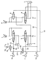
第1実施形態(図1参照)
1は第1油圧ポンプで、この第1油圧ポンプ1に対してバケットシリンダ2とブームシリンダ3がそれぞれバケット用及びブーム用両コントロールバルブ4,5を介してパラレルに接続されている。
【0024】
6は第2油圧ポンプで、この第2油圧ポンプ6に対してブームシリンダ3とアームシリンダ7がそれぞれブーム合流用及びアーム用両コントロールバルブ8,9を介してパラレルに接続されている。Tはタンクである。
【0025】
各コントロールバルブ4,5,8,9は、それぞれ操作手段としてのバケット用、ブーム用、アーム用各リモコン弁10,11,12からのパイロット圧によって切換わり作動する油圧パイロット弁として構成され、バケット掘削、ブーム上げ、アーム引きの三動作の複合操作時に、バケット用、ブーム用両コントロールバルブ4,5はそれぞれ図左側の位置(バケット掘削位置、ブーム上げ位置)に、またブーム合流用及びアーム用両コントロールバルブ9は図右側の位置(合流位置、アーム引き位置)にそれぞれセットされる。
【0026】
これにより、第1油圧ポンプ1からバケット、ブーム両シリンダ2,3に、第2油圧ポンプ6からブーム、アーム両シリンダ3,7にそれぞれコントロールバルブ操作量に応じた流量が送られて各シリンダ2,3,7が伸長作動する。
【0027】
図1では、各コントロールバルブ4,5,8,9にパイロット圧を供給するパイロットラインとして、バケット掘削側パイロットライン13、ブーム上げ側パイロットライン14、同パイロットライン14にパラレルに接続された合流パイロットライン15、アーム引き側パイロットライン16のみを示し、バケット戻し側、ブーム下げ側、合流停止側、アーム押し側の各パイロットラインの図示を省略している。
【0028】
この油圧回路においては、バケット掘削側パイロットライン13にタンクライン17が接続され、このタンクライン17に、パイロット圧に応じて開度が変化する油圧パイロット弁であるバケット掘削側切換弁18と、第1の絞り19とが設けられるとともに、タンクライン17よりも上流側でパイロットライン13に第2の絞り20が設けられてパイロット圧制御手段が構成されている。
【0029】
また、バケット掘削側切換弁18のパイロットポートは制御ライン21を介してブーム上げ側パイロットライン14に接続され、制御ライン21に、アーム引きパイロット圧に応じて開度が変化する油圧パイロット弁であるブーム上げ側切換弁22が設けられている。
【0030】
この構成において、バケット掘削、ブーム上げ、アーム引きの複合操作が行われると、各パイロットライン13,14,15,16に操作量に応じたパイロット圧P1,P2,P3が作用する。
【0031】
このとき、アーム引きパイロット圧P3がブーム上げ側切換弁22のパイロットポートに供給されて同切換弁22がアーム引きパイロット圧P3に応じた開度で開き、同切換弁22の開度に応じたブーム上げパイロット圧P2aがバケット掘削側切換弁18のパイロットポートに供給されて同切換弁18がブーム上げパイロット圧P2aに応じた開度で開く。
【0032】
一方、バケット掘削側パイロット圧P1は、第2の絞り20によって中間圧(たとえば1/2程度)に減圧され、バケット掘削側切換弁18の開通に伴う第1の絞り19の働きによりさらに減圧されてバケット用コントロールバルブ4のバケット掘削側パイロットポートに供給される。
【0033】
この作用により、バケット用コントロールバルブ4のストロークが抑えられ、同バルブ4での絞り作用によって第1油圧ポンプ1のポンプ圧が上昇するため、負荷圧の高いブームシリンダ3にも圧油が供給され、ブーム上げ動作が確保される。すなわち、バケット掘削、ブーム上げ、アーム引きの複合操作をオペレータの意思通りに行うことが可能となる。
【0034】
しかも、公知技術のようにバケット用コントロールバルブ4の入口側通路を絞るのではなく、同バルブ4に供給されるパイロット圧を減圧することによりバルブストロークを抑えてブーム上げ動作を確保するため、たとえポンプ駆動源であるエンジン回転数の低下によってポンプ流量が減少しても、タンク流量もコントロールバルブ4で同時に絞られることから、キャビテーションが発生するおそれがなくなる。
【0035】
また、バケット掘削側パイロット圧を減圧する構成であるため、メイン通路に絞り手段を設ける公知技術と比較して構成がシンプルで部品コスト、組み込みコストが安くてすみ、既存機械への後付けも簡単となる。
【0036】
なお、ブーム上げ及びアーム引きの両操作が同時に行われていない場合には、バケット掘削側切換弁18が作動しないため、バケット掘削側パイロット圧の絞り作用は働かず、通常の速度でバケット掘削動作が行われる。
【0037】
第2実施形態(図2参照)
以下の実施形態では、第1実施形態との相違点のみを説明する。
【0038】
バケット掘削側パイロット圧の減圧度は、バケット重量やオペレータの動作特性の好み等に応じて調整できるのが望ましく、第1実施形態の場合、この減圧度の調整は、両絞り19,20の選択、交換によって行うことができる。
【0039】
これに対し、第2実施形態においては、第1及び第2両絞り19,20を可変絞りとして構成している。
【0040】
こうすれば、一つの機械でバケットが交換された場合やオペレータが交代した場合等に、両絞り19,20の開度調整によって減圧度を自在に調整することができる。
【0041】
第3実施形態(図3,4参照)
第3実施形態においては、パイロット圧制御手段として、図3に示すようにバケット掘削側ライン13に電磁比例減圧弁(以下、単に減圧弁という)23を設けるとともに、ブーム上げパイロット圧P2及びアーム引きパイロット圧P3を検出してコントローラ24に送る圧力センサ25,26を設け、コントローラ24から減圧弁23に両パイロット圧P2,P3に応じた二次圧指令信号を送ってバケット掘削側パイロット圧を減圧する構成をとっている。
【0042】
この点の作用を図4によって詳述すると、ステップS1,S2でブーム上げパイロット圧P2及びアーム引きパイロット圧P3を読み込み、ステップS3,S4でブーム上げ操作があるか否か、及びアーム引き操作があるか否かがそれぞれ判断される。
【0043】
そして、両操作がある場合に、ステップS5において、両パイロット圧P2,P3の和を横軸、減圧弁23の二次圧(減圧後の圧力)を縦軸にとって予め設定された絞り特性に基づいて減圧弁23に二次圧指令信号を出力する。
【0044】
これにより、第1実施形態同様、三動作の複合操作時にバケット掘削側コントロールバルブ4のストロークを抑えてポンプ圧を上昇させ、ブーム上げ動作を確保することができる。
【0045】
また、ブーム上げ、バケット掘削、アーム引き各動作についての特性の選択、変更をコントローラ24での調整(たとえばトリマーによる調整)によってより一層簡単に行うことができる。
【0046】
第4実施形態(図5,6参照)
第4実施形態においては、第3実施形態の構成に加えて、図5に示すようにブームシリンダ3のブーム上げ側(シリンダヘッド)圧力と第1油圧ポンプ1の作動圧(ポンプ圧)をそれぞれ圧力センサ27,28で検出してコントローラ24に入力し、ポンプ圧がブーム上げ側圧力よりも低いことを前提としてバケット掘削側パイロット圧の減圧作用が働くように構成している。
【0047】
すなわち、図6に示すように、ステップS1〜ステップS4でブーム上げパイロット圧P2、アーム引きパイロットP3、ブームシリンダ圧、第1油圧ポンプ1の圧力をそれぞれ読み込み、ステップS5,S6でブーム上げ操作及びアーム引き操作の有無を判断した後、ステップS7でポンプ圧とシリンダ圧を比較し、ポンプ圧がシリンダ圧よりも低い場合に限り、ステップS8,S9で減圧弁二次圧の演算、出力を行う。
【0048】
こうすれば、ポンプ圧のフィードバックを行うため、必要以上にポンプ圧が低下してバケット掘削動作の速度が落ち、操作性が損なわれるおそれがない。
【0049】
ところで、第1実施形態の変形例として、バケット掘削側及びブーム上げ側両切換弁18,22として電磁切換弁を用い、圧力センサで検出したブーム上げ側パイロット圧及びアーム引き側パイロット圧に応じてコントローラで同切換弁18,22を制御する構成をとってもよい。
【0050】
【発明の効果】
上記のように本発明によると、ブーム上げとアーム引きとバケット掘削の複合操作時に、バケット用コントロールバルブのパイロット圧を減圧して同バルブのストロークを抑、これによりコントロールバルブそのものによる絞り作用を働かせてポンプ圧を上昇させ、ブーム上げ動作を確保する構成としたから、バケット用コントロールバルブの入口側通路(メイン通路)を絞る公知技術と比較して、たとえエンジン回転数の低下によってポンプ流量が減少しても、タンク流量も同時に絞られることからキャビテーションが発生するおそれがなくなる。
【0051】
また、バケット用コントロールバルブのパイロット圧を減圧するため、メイン流量を絞る公知技術と比較して構成がシンプルでコストが安くてすみ、後付けも容易となる。
【図面の簡単な説明】
【図1】 本発明の第1実施形態にかかる油圧回路を示す図である。
【図2】 本発明の第2実施形態にかかる油圧回路を示す図である。
【図3】 本発明の第3実施形態にかかる油圧回路を示す図である。
【図4】 同実施形態の作用を説明するためのフローチャートである。
【図5】 本発明の第4実施形態にかかる油圧回路を示す図である。
【図6】 同実施形態の作用を説明するためのフローチャートである。
【符号の説明】
1 第1油圧ポンプ
2 バケットシリンダ
3 ブームシリンダ
4 バケット用コントロールバルブ
5 ブーム用コントロールバルブ
6 第2油圧ポンプ
7 アームシリンダ
8 ブーム合流用コントロールバルブ
9 アーム用コントロールバルブ
10,11,12 操作手段としてのリモコン弁
13 バケット掘削側パイロットライン
14 ブーム上げ側パイロットライン
18 バケット掘削側切換弁
19 第1の絞り
20 第2の絞り
22 ブーム上げ側切換弁
23 電磁比例減圧弁
24 コントローラ
25 ブーム上げ検出手段としての圧力センサ
26 アーム引き検出手段としての圧力センサ
27 ブーム上げ圧力検出手段としての圧力センサ
28 ポンプ圧検出手段としての圧力センサ[0001]
BACKGROUND OF THE INVENTION
The present invention relates to a hydraulic circuit of a hydraulic excavator configured to ensure a boom raising operation when a boom and a bucket driven by a common hydraulic pump are simultaneously operated.
[0002]
[Prior art]
The work attachment of a hydraulic excavator is composed of a boom, an arm, a bucket, and a hydraulic cylinder (boom cylinder, arm cylinder, bucket cylinder) that drives them, and raises / lowers the boom, pushes / pulls the arm, and excavates the bucket (rake). ) / Return operations perform various operations such as excavation and loading.
[0003]
In this case, as a combination of the hydraulic pump and the cylinder, a boom cylinder that requires a large flow rate and a bucket cylinder that requires a smaller flow rate are usually driven by a common hydraulic pump.
[0004]
When the two-pump method is adopted, the boom cylinder and bucket cylinder are driven by the first hydraulic pump, while the arm cylinder is driven by the second hydraulic pump, and a part of the pressure oil from the second hydraulic pump is supplied to the boom cylinder. To ensure the boom operating speed.
[0005]
However, in this configuration, the boom raising operation is a heavy load with respect to the bucket excavation and arm pulling operation in which the own weight acts in the operation direction at the time of combined operation in which the three operations of boom raising, arm pulling, and bucket excavation are performed simultaneously in the air. Therefore, the pressure oil from both hydraulic pumps flows preferentially to the bucket cylinder and the arm cylinder, and there is a problem that the boom raising operation is not performed as intended by the operator.
[0006]
Conventionally, as a means for solving this problem, as disclosed in Patent Document 1, a flow rate control valve is provided in the inlet side passage of the bucket cylinder control valve, and the supply flow rate to the bucket cylinder is reduced during the combined operation of three operations. A technique for securing a boom raising operation by raising the pump pressure to be higher than the load pressure of the boom cylinder by throttling is known.
[0007]
[Patent Document 1]
Japanese Patent Laid-Open No. 8-13547
[Problems to be solved by the invention]
However, according to the publicly known technique for restricting the main passage of the bucket cylinder as described above, the flow rate at the inlet is reduced while the bucket control valve is in full stroke, while the return flow rate to the tank is not restricted. If the rotational speed of the engine, which is a pump drive source, decreases due to the influence of a load and the like, and the pump flow rate decreases, the adverse effect that the inlet flow rate becomes insufficient and cavitation occurs.
[0009]
In addition, it is troublesome to install a flow control valve in an existing machine (retrofitting) in order to narrow down the main passage, and the cost is high, and the adjustment to increase / decrease in the bucket weight (bucket cylinder load) is troublesome. There was also.
[0010]
Accordingly, the present invention provides a hydraulic circuit for a hydraulic excavator that can ensure a boom raising operation during complex operation, is free of cavitation, can be easily retrofitted, and can be easily adjusted to increase or decrease bucket weight. .
[0011]
[Means for Solving the Problems]
The invention of claim 1 includes a boom, an arm, a bucket, a boom cylinder that drives the boom, an arm cylinder that drives the arm, and a bucket cylinder that drives the bucket, and supplies oil from a first hydraulic pump to the boom cylinder. and boom control valve to the bucket cylinder, while supplying in parallel via the bucket control valve, parallel to the oil from the second hydraulic pump boom confluence control valve, to the boom cylinder and the arm cylinder through the arm control valve In the hydraulic circuit of a hydraulic excavator, in which a hydraulic pilot switching valve that is switched and operated by a pilot pressure corresponding to the operation amount of the operating means is used as each control valve, the bucket control Bar A tank line is connected to the bucket excavation side pilot line, and a bucket excavation side switching valve whose opening degree changes according to the boom raising pilot pressure and the arm pulling pilot pressure and a first throttle are provided in the tank line. In addition, by providing a second throttle in the pilot line upstream of the tank line, the bucket control valve bucket can be operated when the boom raising, arm pulling, and bucket excavation operations are performed simultaneously. A pilot pressure control means for reducing the bucket excavation side pilot pressure supplied to the excavation side pilot port in accordance with the boom raising operation amount is configured .
[0012]
According to a second aspect of the present invention, in the configuration of the first aspect, a boom raising pilot valve which is connected to a boom raising pilot line and has a boom raising switching valve whose opening degree is changed by an arm pulling pilot pressure is an output of the boom raising switching valve. The pressure is configured to be supplied to the pilot port of the bucket excavation switching valve .
[0013]
According to a third aspect of the present invention, in the configuration of the first or second aspect, as the first and second throttles, variable throttles capable of adjusting the opening degree are provided .
[0014]
According to a fourth aspect of the present invention, there is provided a boom, an arm, a bucket, a boom cylinder for driving the boom, an arm cylinder for driving the arm, and a bucket cylinder for driving the bucket , and oil from a first hydraulic pump is supplied to the boom cylinder. and boom control valve to the bucket cylinder, while supplying in parallel via the bucket control valve, parallel to the oil from the second hydraulic pump boom confluence control valve, to the boom cylinder and the arm cylinder through the arm control valve In a hydraulic circuit of a hydraulic excavator in which a hydraulic pilot switching valve that is switched and operated by a pilot pressure corresponding to the operation amount of the operating means is used as each control valve, the bucket control valve of The electromagnetic proportional pressure reducing valve provided in the pilot excavation side pilot line, the arm pulling detecting means for detecting the arm pulling operation amount, the boom raising detecting means for detecting the boom raising operation amount, and the electromagnetic proportional pressure reducing valve When the boom raising, arm pulling, and bucket excavation operations are simultaneously performed by the controller that issues a secondary pressure command corresponding to the arm pulling operation amount and the boom raising operation amount detected by both detection means, the bucket The pilot pressure control means is configured to reduce the bucket excavation side pilot pressure supplied to the bucket excavation side pilot port of the control valve in accordance with the boom raising operation amount .
[0015]
According to a fifth aspect of the present invention, in the configuration of the fourth aspect, the pilot pressure control means includes a boom raising pressure detecting means for detecting a boom raising side pressure of the boom cylinder, and a pump pressure detection for detecting an operating pressure of the first hydraulic pump. And a secondary pressure command for the electromagnetic proportional pressure reducing valve is provided on condition that the operating pressure of the first hydraulic pump is lower than the boom raising pressure .
[0016]
According to the above configuration, during the combined operation of raising the boom, pulling the arm, and excavating the bucket, the pilot pressure of the bucket control valve is reduced and the stroke of the valve is suppressed. Rises and the boom raising operation is secured.
[0017]
That is, rather than restricting the inlet side passage (main passage) of the bucket control valve, the pilot pressure supplied to the valve is reduced to ensure the boom raising operation. However, since the tank flow rate is simultaneously reduced, there is no risk of cavitation.
[0018]
In addition, since the pilot pressure of the bucket control valve is reduced, the configuration is simple and low in cost as compared with the known technique for reducing the main flow rate, and retrofit becomes easy.
[0019]
In particular, according to the configurations of claims 1 to 3 , since the pressure is reduced by the throttling means, the configuration is simpler, the parts cost is low, and retrofit becomes easier.
[0020]
Further, it is easy to adjust the degree of decompression to increase / decrease of the bucket weight, the operator's preference of the operating characteristics, etc. (especially easy with the configuration of
[0021]
Meanwhile, according to the configuration of
[0022]
Moreover, according to the structure of
[0023]
DETAILED DESCRIPTION OF THE INVENTION
The first embodiment (see FIG. 1)
Reference numeral 1 denotes a first hydraulic pump. A
[0024]
[0025]
Each of the
[0026]
As a result, a flow rate corresponding to the control valve operation amount is sent from the first hydraulic pump 1 to the bucket and
[0027]
In FIG. 1, as pilot lines for supplying pilot pressure to the
[0028]
In this hydraulic circuit, a
[0029]
Further, the pilot port of the bucket excavation
[0030]
In this configuration, when combined operations of bucket excavation, boom raising, and arm pulling are performed, pilot pressures P1, P2, and P3 corresponding to the operation amounts are applied to the
[0031]
At this time, the arm pulling pilot pressure P3 is supplied to the pilot port of the boom raising
[0032]
On the other hand, the bucket excavation side pilot pressure P1 is reduced to an intermediate pressure (for example, about 1/2) by the
[0033]
By this action, the stroke of the bucket control valve 4 is suppressed, and the pump pressure of the first hydraulic pump 1 is increased by the throttle action of the valve 4, so that the pressure oil is also supplied to the
[0034]
In addition, instead of restricting the inlet side passage of the bucket control valve 4 as in the known art, the pilot pressure supplied to the valve 4 is reduced to suppress the valve stroke and ensure the boom raising operation. Even if the pump flow rate decreases due to a decrease in the engine speed, which is the pump drive source, the tank flow rate is simultaneously throttled by the control valve 4, thereby eliminating the possibility of cavitation.
[0035]
In addition, since the bucket excavation side pilot pressure is reduced, the configuration is simple compared to the known technology in which the throttle means is provided in the main passage, and the parts and assembly costs are low, and retrofitting to existing machines is easy. Become.
[0036]
If both the boom raising operation and the arm pulling operation are not performed at the same time, the bucket excavation
[0037]
Second embodiment (see FIG. 2)
In the following embodiments, only differences from the first embodiment will be described.
[0038]
The pressure reduction degree of the bucket excavation side pilot pressure is preferably adjustable in accordance with the bucket weight, the operator's preference of operating characteristics, and the like. In the first embodiment, the pressure reduction degree is selected by selecting both
[0039]
On the other hand, in the second embodiment, both the first and
[0040]
In this way, the degree of pressure reduction can be freely adjusted by adjusting the opening of both
[0041]
Third embodiment (see FIGS. 3 and 4)
In the third embodiment, as a pilot pressure control means, an electromagnetic proportional pressure reducing valve (hereinafter simply referred to as a pressure reducing valve) 23 is provided on the bucket
[0042]
The operation of this point will be described in detail with reference to FIG. 4. In steps S1 and S2, the boom raising pilot pressure P2 and the arm pulling pilot pressure P3 are read. In steps S3 and S4, whether there is a boom raising operation and whether the arm pulling operation is performed. Each is determined whether or not there is.
[0043]
Then, when there are both operations, in step S5, the sum of the pilot pressures P2 and P3 is set on the horizontal axis and the secondary pressure of the pressure reducing valve 23 (pressure after pressure reduction) is set on the vertical axis, based on a preset throttle characteristic. The secondary pressure command signal is output to the
[0044]
Thus, as in the first embodiment, it is possible to increase the pump pressure by suppressing the stroke of the bucket excavation side control valve 4 during the combined operation of the three operations, and to ensure the boom raising operation.
[0045]
Further, selection and change of characteristics for the boom raising, bucket excavation, and arm pulling operations can be performed more easily by adjusting the controller 24 (for example, adjustment by a trimmer).
[0046]
Fourth embodiment (see FIGS. 5 and 6)
In the fourth embodiment, in addition to the configuration of the third embodiment, the boom raising side (cylinder head) pressure of the
[0047]
That is, as shown in FIG. 6, the boom raising pilot pressure P2, the arm pulling pilot P3, the boom cylinder pressure, and the pressure of the first hydraulic pump 1 are read in steps S1 to S4, respectively, and the boom raising operation and the steps are performed in steps S5 and S6. After determining the presence or absence of the arm pulling operation, the pump pressure and the cylinder pressure are compared in step S7, and only when the pump pressure is lower than the cylinder pressure, the pressure reducing valve secondary pressure is calculated and output in steps S8 and S9. .
[0048]
In this case, since the pump pressure is fed back, the pump pressure is reduced more than necessary, the speed of the bucket excavation operation is reduced, and the operability is not impaired.
[0049]
By the way , as a modification of the first embodiment, electromagnetic switching valves are used as both the bucket excavation side and boom raising
[0050]
【The invention's effect】
As described above, according to the present invention, during the combined operation of raising the boom, pulling the arm, and excavating the bucket, the pilot pressure of the bucket control valve is reduced to suppress the stroke of the valve, thereby causing the throttle action by the control valve itself to work. As a result, the pump pressure is increased and the boom raising operation is ensured. Therefore, the pump flow rate is reduced due to a decrease in the engine speed, compared with the known technology that restricts the inlet side passage (main passage) of the bucket control valve. However, since the tank flow rate is also reduced, there is no possibility of cavitation.
[0051]
Further, since the pilot pressure of the bucket control valve is reduced, the configuration is simple and the cost can be reduced compared to the known technique for reducing the main flow rate, and retrofitting becomes easy.
[Brief description of the drawings]
FIG. 1 is a diagram showing a hydraulic circuit according to a first embodiment of the present invention.
FIG. 2 is a diagram showing a hydraulic circuit according to a second embodiment of the present invention.
FIG. 3 is a diagram showing a hydraulic circuit according to a third embodiment of the present invention.
FIG. 4 is a flowchart for explaining the operation of the embodiment.
FIG. 5 is a diagram showing a hydraulic circuit according to a fourth embodiment of the present invention.
FIG. 6 is a flowchart for explaining the operation of the embodiment.
[Explanation of symbols]
DESCRIPTION OF SYMBOLS 1 1st
Claims (5)
Priority Applications (4)
| Application Number | Priority Date | Filing Date | Title |
|---|---|---|---|
| JP2002318556A JP3818252B2 (en) | 2002-10-31 | 2002-10-31 | Hydraulic circuit of excavator |
| EP03256761A EP1416096B1 (en) | 2002-10-31 | 2003-10-27 | Hydraulic excavator with a hydraulic circuit |
| AT03256761T ATE483861T1 (en) | 2002-10-31 | 2003-10-27 | HYDRAULIC EXCAVATOR WITH HYDRAULIC CIRCUIT |
| DE60334430T DE60334430D1 (en) | 2002-10-31 | 2003-10-27 | Hydraulic excavator with hydraulic circuit |
Applications Claiming Priority (1)
| Application Number | Priority Date | Filing Date | Title |
|---|---|---|---|
| JP2002318556A JP3818252B2 (en) | 2002-10-31 | 2002-10-31 | Hydraulic circuit of excavator |
Publications (2)
| Publication Number | Publication Date |
|---|---|
| JP2004150198A JP2004150198A (en) | 2004-05-27 |
| JP3818252B2 true JP3818252B2 (en) | 2006-09-06 |
Family
ID=32089592
Family Applications (1)
| Application Number | Title | Priority Date | Filing Date |
|---|---|---|---|
| JP2002318556A Expired - Fee Related JP3818252B2 (en) | 2002-10-31 | 2002-10-31 | Hydraulic circuit of excavator |
Country Status (4)
| Country | Link |
|---|---|
| EP (1) | EP1416096B1 (en) |
| JP (1) | JP3818252B2 (en) |
| AT (1) | ATE483861T1 (en) |
| DE (1) | DE60334430D1 (en) |
Families Citing this family (14)
| Publication number | Priority date | Publication date | Assignee | Title |
|---|---|---|---|---|
| JP4655795B2 (en) | 2005-07-15 | 2011-03-23 | コベルコ建機株式会社 | Hydraulic control device of excavator |
| EP1832476B1 (en) | 2006-03-07 | 2008-12-31 | Mazda Motor Corporation | Vehicle rear structure provided with curtain air bag device |
| JP4931048B2 (en) * | 2006-07-31 | 2012-05-16 | キャタピラー エス エー アール エル | Control device for work machine |
| JP5342293B2 (en) * | 2009-03-26 | 2013-11-13 | 住友建機株式会社 | Hydraulic circuit for construction machinery |
| JP5272211B2 (en) * | 2009-07-07 | 2013-08-28 | 住友建機株式会社 | Hydraulic circuit for construction machinery |
| JP5079827B2 (en) | 2010-02-10 | 2012-11-21 | 日立建機株式会社 | Hydraulic drive device for hydraulic excavator |
| JP5475507B2 (en) * | 2010-02-28 | 2014-04-16 | 住友建機株式会社 | Hydraulic control device of excavator |
| JP5406087B2 (en) * | 2010-03-18 | 2014-02-05 | ヤンマー株式会社 | Hydraulic circuit of work vehicle |
| WO2014081053A1 (en) * | 2012-11-23 | 2014-05-30 | 볼보 컨스트럭션 이큅먼트 에이비 | Apparatus and method for controlling preferential function of construction machine |
| US9890801B2 (en) | 2013-03-22 | 2018-02-13 | Hitachi Construction Machinery Tierra Co., Ltd. | Hydraulic drive system for construction machine |
| US9394929B2 (en) | 2013-08-01 | 2016-07-19 | Caterpillar Inc. | Reducing dig force in hydraulic implements |
| JP6220228B2 (en) * | 2013-10-31 | 2017-10-25 | 川崎重工業株式会社 | Hydraulic drive system for construction machinery |
| JP6196567B2 (en) * | 2014-03-06 | 2017-09-13 | 川崎重工業株式会社 | Hydraulic drive system for construction machinery |
| JP7207060B2 (en) * | 2019-03-22 | 2023-01-18 | コベルコ建機株式会社 | Working machine hydraulic drive |
Family Cites Families (7)
| Publication number | Priority date | Publication date | Assignee | Title |
|---|---|---|---|---|
| US172650A (en) * | 1876-01-25 | Improvement in hydraulic elevators | ||
| JP2607258B2 (en) * | 1988-03-30 | 1997-05-07 | 日立建機株式会社 | Hydraulic control circuit of work machine |
| JP2892939B2 (en) * | 1994-06-28 | 1999-05-17 | 日立建機株式会社 | Hydraulic circuit equipment of hydraulic excavator |
| JP3612256B2 (en) * | 1999-12-22 | 2005-01-19 | 新キャタピラー三菱株式会社 | Hydraulic circuit of work machine |
| DE10047175A1 (en) * | 2000-09-22 | 2002-04-11 | Mannesmann Rexroth Ag | Method and control arrangement for controlling hydraulic consumers |
| JP3901470B2 (en) * | 2001-05-15 | 2007-04-04 | 新キャタピラー三菱株式会社 | Fluid pressure circuit control system |
| JP2003232303A (en) * | 2002-02-12 | 2003-08-22 | Shin Caterpillar Mitsubishi Ltd | Fluid pressure circuit |
-
2002
- 2002-10-31 JP JP2002318556A patent/JP3818252B2/en not_active Expired - Fee Related
-
2003
- 2003-10-27 DE DE60334430T patent/DE60334430D1/en not_active Expired - Lifetime
- 2003-10-27 AT AT03256761T patent/ATE483861T1/en not_active IP Right Cessation
- 2003-10-27 EP EP03256761A patent/EP1416096B1/en not_active Expired - Lifetime
Also Published As
| Publication number | Publication date |
|---|---|
| DE60334430D1 (en) | 2010-11-18 |
| JP2004150198A (en) | 2004-05-27 |
| EP1416096A1 (en) | 2004-05-06 |
| ATE483861T1 (en) | 2010-10-15 |
| EP1416096B1 (en) | 2010-10-06 |
Similar Documents
| Publication | Publication Date | Title |
|---|---|---|
| EP1743980B1 (en) | Hydraulic excavator having a hydraulic control apparatus | |
| JP3818252B2 (en) | Hydraulic circuit of excavator | |
| US9051712B2 (en) | Hydraulic system for working machine | |
| JP5572586B2 (en) | Hydraulic drive device for work machine | |
| JP3992612B2 (en) | Backhoe hydraulic circuit structure | |
| JP3985756B2 (en) | Hydraulic control circuit for construction machinery | |
| US8726649B2 (en) | Controller and work machine provided therewith | |
| US8375989B2 (en) | Method of operating a control valve assembly for a hydraulic system | |
| KR20140074306A (en) | Control system for operating work device for construction machine | |
| WO2019220954A1 (en) | Hydraulic shovel drive system | |
| JP6231917B2 (en) | Hydraulic excavator drive system | |
| JP4240075B2 (en) | Hydraulic control circuit of excavator | |
| JP2003004003A (en) | Hydraulic control circuit of hydraulic shovel | |
| KR20090036086A (en) | Method for controlling pump of working machine | |
| JP2008025706A (en) | Hydraulic control circuit for working machine | |
| JP2011226491A (en) | Turning hydraulic circuit of hydraulic shovel | |
| JP5404597B2 (en) | Hydraulic working machine | |
| JP2009167659A (en) | Hydraulic control circuit of utility machine | |
| JP3056220B2 (en) | Hydraulic drive | |
| JP2004076904A (en) | Hydraulic cylinder control device of construction machine | |
| JP2008180203A (en) | Control device | |
| JP3097973B2 (en) | Hydraulic working machine hydraulic circuit | |
| JP2010065733A (en) | Hydraulic control circuit for working machine | |
| JP6989548B2 (en) | Construction machinery | |
| JP3680689B2 (en) | Excavator dozer control device |
Legal Events
| Date | Code | Title | Description |
|---|---|---|---|
| A621 | Written request for application examination |
Free format text: JAPANESE INTERMEDIATE CODE: A621 Effective date: 20040928 |
|
| A977 | Report on retrieval |
Free format text: JAPANESE INTERMEDIATE CODE: A971007 Effective date: 20060203 |
|
| A131 | Notification of reasons for refusal |
Free format text: JAPANESE INTERMEDIATE CODE: A131 Effective date: 20060207 |
|
| A521 | Request for written amendment filed |
Free format text: JAPANESE INTERMEDIATE CODE: A523 Effective date: 20060404 |
|
| TRDD | Decision of grant or rejection written | ||
| A01 | Written decision to grant a patent or to grant a registration (utility model) |
Free format text: JAPANESE INTERMEDIATE CODE: A01 Effective date: 20060523 |
|
| A61 | First payment of annual fees (during grant procedure) |
Free format text: JAPANESE INTERMEDIATE CODE: A61 Effective date: 20060605 |
|
| R150 | Certificate of patent or registration of utility model |
Free format text: JAPANESE INTERMEDIATE CODE: R150 |
|
| FPAY | Renewal fee payment (event date is renewal date of database) |
Free format text: PAYMENT UNTIL: 20090623 Year of fee payment: 3 |
|
| FPAY | Renewal fee payment (event date is renewal date of database) |
Free format text: PAYMENT UNTIL: 20100623 Year of fee payment: 4 |
|
| FPAY | Renewal fee payment (event date is renewal date of database) |
Free format text: PAYMENT UNTIL: 20100623 Year of fee payment: 4 |
|
| FPAY | Renewal fee payment (event date is renewal date of database) |
Free format text: PAYMENT UNTIL: 20110623 Year of fee payment: 5 |
|
| FPAY | Renewal fee payment (event date is renewal date of database) |
Free format text: PAYMENT UNTIL: 20110623 Year of fee payment: 5 |
|
| FPAY | Renewal fee payment (event date is renewal date of database) |
Free format text: PAYMENT UNTIL: 20120623 Year of fee payment: 6 |
|
| LAPS | Cancellation because of no payment of annual fees |