EP1447288A2 - Wischeranlage für Fahrzeug-Windschutzscheiben - Google Patents
Wischeranlage für Fahrzeug-Windschutzscheiben Download PDFInfo
- Publication number
- EP1447288A2 EP1447288A2 EP04001638A EP04001638A EP1447288A2 EP 1447288 A2 EP1447288 A2 EP 1447288A2 EP 04001638 A EP04001638 A EP 04001638A EP 04001638 A EP04001638 A EP 04001638A EP 1447288 A2 EP1447288 A2 EP 1447288A2
- Authority
- EP
- European Patent Office
- Prior art keywords
- wiper
- vehicle
- module
- control unit
- modules
- Prior art date
- Legal status (The legal status is an assumption and is not a legal conclusion. Google has not performed a legal analysis and makes no representation as to the accuracy of the status listed.)
- Granted
Links
Images


Classifications
-
- B—PERFORMING OPERATIONS; TRANSPORTING
- B60—VEHICLES IN GENERAL
- B60S—SERVICING, CLEANING, REPAIRING, SUPPORTING, LIFTING, OR MANOEUVRING OF VEHICLES, NOT OTHERWISE PROVIDED FOR
- B60S1/00—Cleaning of vehicles
- B60S1/02—Cleaning windscreens, windows or optical devices
- B60S1/04—Wipers or the like, e.g. scrapers
- B60S1/06—Wipers or the like, e.g. scrapers characterised by the drive
- B60S1/08—Wipers or the like, e.g. scrapers characterised by the drive electrically driven
- B60S1/0814—Wipers or the like, e.g. scrapers characterised by the drive electrically driven using several drive motors; motor synchronisation circuits
-
- B—PERFORMING OPERATIONS; TRANSPORTING
- B60—VEHICLES IN GENERAL
- B60S—SERVICING, CLEANING, REPAIRING, SUPPORTING, LIFTING, OR MANOEUVRING OF VEHICLES, NOT OTHERWISE PROVIDED FOR
- B60S1/00—Cleaning of vehicles
- B60S1/02—Cleaning windscreens, windows or optical devices
- B60S1/04—Wipers or the like, e.g. scrapers
- B60S1/06—Wipers or the like, e.g. scrapers characterised by the drive
- B60S1/08—Wipers or the like, e.g. scrapers characterised by the drive electrically driven
Definitions
- the invention relates to a wiper system for vehicle windshields with at least two wipers the preamble of claim 1.
- DE 101 13 678 A1 also describes a wiper system for Motor vehicles known, in which two wiper modules, consisting of wiper motor, gearbox and electronic Control, correspond with each other and being that driver-side wiper module a reversing motor and that a wiper module on the passenger side having.
- the wiper module on the driver's side has a Control line with the central electronics of the motor vehicle connected and can be connected to one of them Put the wiper switch into operation.
- the aim of the present solution is the number of different wiper modules to be provided reduce and thus the manufacturing and storage costs reduce.
- the wiper system according to the invention with the free configurable controls of the wiper modules has the Advantage that the same wiper modules are more versatile for Left-hand drive and right-hand drive vehicles of various types Vehicle types can be used as they only after they have been installed can be configured as a master or slave module. This facilitates assembly and reduces the cost of Manufacturing and warehousing as with the remaining Type parts higher quantities are produced.
- a connectable to the control unit of the vehicle Diagnostic device according to the vehicle type and the Vehicle variant can be configured.
- the wiper system for each wiper module, information about the selection of the wiping characteristics dependent on the vehicle type with detection of the upper and lower reversal or parking position in one Vehicle identification of the vehicle control unit stored.
- the wiper system furthermore the respective wiping characteristic in an expedient manner and parking or reverse positions of the master and slave module via the vehicle identification from the vehicle control unit in the Control of the master module enabled, so that in in a known manner, the control of the master module the setpoints for the slave module via the serial interface on its Control transfers.
- it is about the vehicle identifier stored in the vehicle control unit (Vehicle type and left-hand drive or right-hand drive variant) the control of the corresponding left or right arranged driver-side wiper module as master control configured.
- the test program can be used advantageously for Connection of both wiper modules to the vehicle electrical system interface through a plausibility check in the vehicle control unit stored left / right-hand drive variant with the Existing available via the wiring system interface Compare data of the wiper modules and if a Deviation via the vehicle control unit an error signal submit.
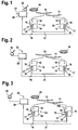
- FIG. 1 is a two-motor wiper system for the Front window of a motor vehicle shown schematically.
- the wiper system has two wipers 10, 11 which in each case on the output axis of a wiper module 12, 13 are attached.
- Each wiper module 12, 13 consists of one Reversing motor 14, a gear 15 and one electronic control 16.
- Each wiper module 12, 13 is with a plus terminal 17 to the vehicle electrical system connect and with a ground connection 18 with the Connected vehicle body, which the ground potential of the Electrical system forms.
- the control of the two wiper modules 12, 13 is via an electrical system interface 19 in the form of a Single-wire control line with a vehicle control unit 20 connected.
- the two wiper modules 12, 13 are also with their controller 16 via a serial interface 21 in Form another control line directly with each other connected.
- On the vehicle control unit 20 there is also a Wiper switch 22 connected to the operation of the Wiper system is triggered.
- the vehicle control unit 20 with, among other things, a diagnostic connection 23 provided, via which
- the Wiper modules 12, 13 use as versatile as possible can, the controller 16 of the wiper modules 12, 13 over the vehicle control unit 20 and the vehicle electrical system interface 19 freely configurable for master or slave control or reconfigurable.
- the controller 16 of the Wiper modules 12, 13 is in a manufacturer's Basic setting configured as slave control.
- This manufacturer's fixed basic setting contains a Variety of wiping characteristics with detection of the upper and lower reverse position as well as a basic position like for example the extended parking area.
- In the manufacturer's basic setting is also a possibly on Master module, callable emergency run with reduced wiping area configured.
- the wiper system is configured at Vehicle manufacturers. There are the first on the assembly line Vehicle control unit 20, the wiper modules 12, 13 and the Wiper switch 22 installed in the vehicle and connected. Then the diagnostic connection 23 in Vehicle control unit 20 stores a vehicle identifier, which is both information about the respective Vehicle variant as a right-hand drive or Left-hand drive vehicles also contain information about the selection of the wiping fields depending on the vehicle type, Parking or upper and lower reversal positions of both Includes wipers.
- the controller 16 of both Wiper modules 12, 13 is initially used as a slave controller configured by the manufacturer.
- the Configuration of the wiper system For this the ignition is first in a first step 30 or the vehicle's power supply (terminal 15) switched on. In a further step 31 the configuration of the Wiper system triggered. The configuration as well as the later one The wiper system is diagnosed using a for electronic control in motor vehicles standardized KEYWORD 2000 protocol format of the electrical system interface 19, which in turn is a standardized LIN single-wire interface (Local Interconnect Network) is executed.
- a parking position run carried out.
- the parking position run makes sure made that both wiper modules 12, 13 their output axis drive into the parking position dependent on the vehicle identification.
- the wiper lever or the Wipers 10, 11 mounted In this defined position of the wiper modules 12, 13 now in step 33 the wiper lever or the Wipers 10, 11 mounted.
- the wiper levers of the wipers are preferred in an extended parking position (EPS), because in this position the wiper linkage in a top layer located so that the tightening torque when mounting the Wiper lever does not attack the motor shaft. Because due a low self-locking of the wiper gearbox it can be excluded that during transport and at the Assembly of the wiper modules has left the top layer before installing the wiper lever an extended one Park position run required. Because the variance of Wiping fields is placed in the upper reverse position and because therefore all vehicle variants expanded the same Have park position is with wiper modules unequal gear positions this parking position run already possible if the wiper system is not yet configured. The parking position run can be done by an appropriate Activate the diagnostic command. Because at this time the Wiper levers are not yet installed, the Park position run also for each wiper module separately respectively.
- EPS extended parking position
- EPS extended parking position
- variable upper reversal positions can be variable wiping areas realize so that these wiper systems regardless of the Right-left-hand drive version in numerous vehicle types can be used.
- the basic setting is the Wiper modules ensure that with an appropriate Diagnostic command triggered a park position run and the extended parking position is approached. If necessary, can for mounting the windshield wipers 10, 11 via the vehicle control unit and its diagnostic connector also one Approached installation position of the wiper modules become.
- the wiper system with those in the vehicle control unit 20 stored data of the vehicle identification is stored in systems, in which according to Figures 1 and 2 both wiper modules to the Vehicle electrical system interface are connected, according to 6 in a first program step 50 the ignition of the vehicle (terminal 15) switched on.
- a further program step 51 is now carried out by the vehicle control unit 20 another plausibility check program called, with the on-board electrical system interface 19 Configuration of the wiper modules 12, 13 as master or The slave module is queried.
- the requested configuration of the wiper modules with the predetermined configuration compared in the im Vehicle control unit 20 contain stored vehicle identification is.
- program step 53 If there is no deviation in program step 52 is determined, according to program step 53 a complete wiping function of the wiper system determined. However, if a deviation occurs in program step 52, thus in the following program step 60 from the vehicle control unit 20 issued an error message and the Wiper system stopped. Since after program step 52 the possible errors are not narrowed down with the error message in program step 60 Reconfiguration of the wiper system required. The The test program then ends in program step 61.
- the Program step 54 determines that either at least one of the wiper modules as a slave instead Master module or vice versa is configured or an incorrect one configured vehicle control unit 20 was installed.
- Further error analysis is now in the next program step 55 a data transmission between the two by means of test data Wiper modules tested via the serial interface 21. With the receipt of data at the wiper module on the The test program recognizes the passenger in the program step 56 that the driver-side wiper module as a master module is configured.
- Program step 72 the expiry of a predetermined timeout time waited for and then in program step 73 found that the master module on the passenger side receives no data via the on-board electrical system interface 19 and no feedback via the serial interface 21 to the master module on the driver side.
- Program step 74 is then carried out by the vehicle control unit 20 issued an error message. With the wiper module on the No wiping is therefore possible on the passenger side.
- the test program then ends in program step 75.
- the timeout monitoring described here can also be used during the wiping operation of the wiper system cyclically or permanently activated in the control of both wiper modules 12a and 12b because during wiping with a high data rate, for example in a cycle of 3ms setpoints and actual values the serial interface 21 between the wiper modules 12a and 12b can be exchanged. Through timeout monitoring can then immediately a fault or a Interruption of the serial interface 21 detected and a corresponding error message via the vehicle control unit 20 are delivered. In addition, then Wipe on the passenger side of the slave module with the Activation of the parking position ended.
- the Receipt of a signal feedback from the wiper module 12a monitored and after a specified timeout period is determined in subsequent program step 83 that if there is no signal feedback, the driver Wiper module 12a as a slave module has no data input via the Vehicle electrical system interface 19 accepted and that passenger-side wiper module 12b as a master module by the missing connection of the electrical system interface 19 none Receiving data.
- This will be in the next program step 84 issued an error message by the vehicle control unit 20 and the wiper system is stopped.
- the test program is ended.
- switch on immediately Emergency program e.g. an interval wiping, wiping in restricted area or approaching a parking location activate.
- the cycle time here is 100ms, for example.
- test programs according to Figures 5 and 6 can just as the 7 and 8 in the vehicle control unit 20 can be called up in parallel or in succession. If an error message occurs, the vehicle control unit 20 a reconfiguration by means of a display the wiper system and / or vehicle identification. In the simplest case, a new entry is the Vehicle identification and reconfiguration of the control in the wiper modules in a motor vehicle workshop a to be connected to the vehicle control unit 20 Diagnostic device.
- the fitting of a wiper system according to the invention with free configurable controls of the wiper modules as master or slave control is not based on that in FIGS 3 shown wiper systems limited. Accordingly the wiper modules can also be used in larger wiper systems Vehicles such as buses and heavy commercial vehicles three wipers can be used. Doing so preferably the driver-side wiper module with a Master controller configured and the controllers of the two other wiper modules via the serial interface connected in parallel to each other and as slave controls configured by the master controller of the Driver-side wiper module, preferably individually, cyclically can be controlled.
Landscapes
- Engineering & Computer Science (AREA)
- Mechanical Engineering (AREA)
- Testing And Monitoring For Control Systems (AREA)
- Control Of Driving Devices And Active Controlling Of Vehicle (AREA)
- Fittings On The Vehicle Exterior For Carrying Loads, And Devices For Holding Or Mounting Articles (AREA)
Abstract
Description
Claims (14)
- Wischeranlage für Fahrzeug-Windschutzscheiben mit mindestens zwei Scheibenwischern (10, 11), die von jeweils einem Wischermodul (12, 13) bestehend aus Reversiermotor (14), Getriebe (15) und elektronischer Steuerung (16), angetrieben werden, wobei das fahrerseitige Wischermodul als Mastermodul über eine Bordnetz-Schnittstelle (19) an ein Fahrzeug-Steuergerät (20) angeschlossen und das beifahrerseitige Wischermodul als Slavemodul über eine serielle Schnittstelle (21) von dem Mastermodul anzusteuern ist, dadurch gekennzeichnet, dass die Steuerung (16) der Wischermodule (12, 13) über das Fahrzeug-Steuergerät (20) und die Bordnetz-Schnittstelle (19) zur Master- oder Slave-Steuerung frei konfigurierbar beziehungsweise umkonfigurierbar ist.
- Wischeranlage nach Anspruch 1, dadurch gekennzeichnet, dass die Steuerung (16) der Wischermodule (12, 13) in einer herstellerseitigen Grundeinstellung als Slave-Steuerung konfiguriert ist.
- Wischeranlage nach Anspruch 2, dadurch gekennzeichnet, dass die Steuerung der Wischermodule (12, 13) als herstellerseitig feste, abrufbare Grundeinstellung mindestens eine Wischkennlinie mit Erfassung einer unteren und oberen Umkehrlage, einer Grundstellung, insbesondere einer erweiterten Parklage und bei unterschiedlichen Getriebelagen eine abrufbare Information über die Getriebelage des Wischermoduls enthält.
- Wischeranlage nach Anspruch 2, dadurch gekennzeichnet, dass in der herstellerseitigen Grundeinstellung ein Notlauf mit verkleinertem Wischfeld konfiguriert ist.
- Wischeranlage nach einem der vorherigen Ansprüche, dadurch gekennzeichnet, dass die Steuerungen aller Wischermodule (12, 13) über die Bordnetz-Schnittstelle (19) an das Fahrzeug-Steuergerät (20) angeschlossen sind.
- Wischeranlage nach einem der vorherigen Ansprüche, dadurch gekennzeichnet, dass die Steuerungen (16) der Wischermodule (12, 13) über einen an sich bekannten Diagnoseanschluss (23) des Fahrzeug-Steuergerätes (20) konfigurierbar beziehungsweise umkonfigurierbar sind.
- Wischeranlage nach einem der vorherigen Ansprüche, dadurch gekennzeichnet, dass über eine in das Fahrzeug-Steuergerät (20) eingegebene beziehungsweise in ihm gespeicherte Fahrzeugkennung als Linkslenker- oder Rechtslenker-Fahrzeug die Steuerung des entsprechend links oder rechts angeordneten fahrerseitigen Wischermoduls als Master-Steuerung konfiguriert ist.
- Wischeranlage nach einem der vorherigen Ansprüche, dadurch gekennzeichnet, dass in einer in das Fahrzeug-Steuergerät (20) eingegebene beziehungsweise in ihm gespeicherten Fahrzeugkennung für jedes Wischermodul eine Information über die Auswahl der vom Fahrzeugtyp abhängigen Wischkennlinien mit Erfassung einer oberen und unteren Umkehrlage abgelegt ist.
- Wischeranlage nach Anspruch 8, dadurch gekennzeichnet, dass über die Fahrzeugkennung die Wischerkennlinien und Park- bzw. Umkehrlagen beider Wischermodule (12, 13) vom Fahrzeug-Steuergerät (20) in der Steuerung (16) des Mastermoduls freigeschaltet sind und dass die Steuerung des Mastermoduls die Sollwerte für das Slavemodul über die serielle Schnittstelle (21) an die Steuerung des Slavemoduls überträgt.
- Wischeranlage nach Anspruch 7 oder 8, dadurch gekennzeichnet, dass nach dem Einschalten der Stromversorgung des Fahrzeugs (Klemme 15) das Fahrzeug-Steuergerät (20) in einem Prüfprogramm mit einer Plausibilitätsprüfung (41-44) die nach der Fahrzeugkennung vorgegebene Konfiguration des Mastermoduls (12; 13; 12a) mit der über die Bordnetz-Schnittstelle (19) aufrufbaren, vorhandenen Konfiguration der Master-Steuerung vergleicht und beim Auftreten einer Abweichung über das Fahrzeug-Steuergerät (20) ein Fehlersignal abgibt.
- Wischeranlage nach Anspruch 10, dadurch gekennzeichnet, dass nach der Plausibilitätsprüfung beim Auftreten einer Abweichung das Fahrzeug-Steuergerät (20) in der Master-Steuerung ein Notlaufprogramm vorzugsweise für beide Wischermodule (12, 13) konfiguriert.
- Wischeranlage nach Anspruch 10, dadurch gekennzeichnet, dass beim Anschluß beider Wischermodule (12, 13) an die Bordnetz-Schnittstelle (19) eine Plausibilitätsprüfung (51-54) eine im Fahrzeug-Steuergerät (20) abgelegte Links-/Rechtslenkerkennung mit den über die Bordnetz-Schnittstelle (19) aufrufbaren, vorhandenen Daten der Wischermodule (12, 13) vergleicht und beim Auftreten einer Abweichung über das Fahrzeug-Steuergerät (20) ein Fehlersignal abgibt.
- Wischeranlage nach einem der vorherigen Ansprüche, dadurch gekennzeichnet, dass die Master-Steuerung und/oder Slave-Steuerung über die serielle Schnittstelle (21) Rückmeldesignale der Slave-Steuerung und/oder Sollwerte der Master-Steuerung in einer Timeout-Überwachung (71) erfasst und beim Ansprechen (72) der Timeout-Überwachung das Slavemodul in die Parklage steuert sowie eine Fehlermeldung (74) an das Fahrzeug-Steuergerät (20) abgibt.
- Wischeranlage nach Anspruch 10, dadurch gekennzeichnet, dass beim Anschluss nur des fahrerseitigen Wischermoduls (12; 13) an die Bordnetz-Schnittstelle (19) das Fahrzeug-Steuergerät (20) in einem weiteren Prüfprogramm einen Datenaustausch auf der Bordnetz-Schnittstelle (19) in einer Timeout-Überwachung (81) erfasst und beim Ansprechen (82) der Timeout-Überwachung die Wischeranlage abschaltet sowie ein Fehlersignal (84) abgibt.
Applications Claiming Priority (2)
| Application Number | Priority Date | Filing Date | Title |
|---|---|---|---|
| DE10306495 | 2003-02-17 | ||
| DE2003106495 DE10306495A1 (de) | 2003-02-17 | 2003-02-17 | Wischeranlage für Fahrzeug-Windschutzscheiben |
Publications (3)
| Publication Number | Publication Date |
|---|---|
| EP1447288A2 true EP1447288A2 (de) | 2004-08-18 |
| EP1447288A3 EP1447288A3 (de) | 2005-08-17 |
| EP1447288B1 EP1447288B1 (de) | 2007-05-23 |
Family
ID=32668087
Family Applications (1)
| Application Number | Title | Priority Date | Filing Date |
|---|---|---|---|
| EP20040001638 Expired - Lifetime EP1447288B1 (de) | 2003-02-17 | 2004-01-27 | Wischeranlage für Fahrzeug-Windschutzscheiben |
Country Status (3)
| Country | Link |
|---|---|
| EP (1) | EP1447288B1 (de) |
| DE (2) | DE10306495A1 (de) |
| ES (1) | ES2286516T3 (de) |
Cited By (6)
| Publication number | Priority date | Publication date | Assignee | Title |
|---|---|---|---|---|
| EP1462326A3 (de) * | 2003-03-25 | 2005-10-12 | Robert Bosch Gmbh | Scheibenwischvorrichtung, insbesondere für ein Kraftfahrzeug |
| WO2011026679A1 (de) * | 2009-09-02 | 2011-03-10 | Robert Bosch Gmbh | Scheibenwischervorrichtung und verfahren zum betreiben einer solchen scheibenwischervorrichtung |
| WO2011032756A1 (de) * | 2009-09-15 | 2011-03-24 | Robert Bosch Gmbh | Antriebssteuerung |
| US8112197B2 (en) * | 2007-11-13 | 2012-02-07 | Mitsuba Corporation | Wiper apparatus control method and wiper control system |
| CN103237692A (zh) * | 2010-11-30 | 2013-08-07 | 法雷奥系统公司 | 用于编程车辆挡风玻璃的擦拭器系统的方法和擦拭器系统 |
| CN104908713A (zh) * | 2014-03-14 | 2015-09-16 | 宝马股份公司 | 在机动车中对玻璃刮拭器进行电子控制的装置和方法 |
Families Citing this family (1)
| Publication number | Priority date | Publication date | Assignee | Title |
|---|---|---|---|---|
| DE102005057703A1 (de) * | 2005-12-02 | 2007-06-21 | Daimlerchrysler Ag | Steuergerät mit Wischerschnittstelle |
Family Cites Families (3)
| Publication number | Priority date | Publication date | Assignee | Title |
|---|---|---|---|---|
| US4900995A (en) * | 1989-06-26 | 1990-02-13 | General Motors Corporation | Vehicle window wipers with alternating symmetrical overlap |
| DE4032922C3 (de) * | 1990-10-17 | 1999-07-29 | Bosch Gmbh Robert | Verfahren zum Wischen einer Scheibe |
| DE10113678A1 (de) * | 2001-03-21 | 2002-10-02 | Bosch Gmbh Robert | Wischeranlage mit zwei Scheibenwischern |
-
2003
- 2003-02-17 DE DE2003106495 patent/DE10306495A1/de not_active Ceased
-
2004
- 2004-01-27 ES ES04001638T patent/ES2286516T3/es not_active Expired - Lifetime
- 2004-01-27 EP EP20040001638 patent/EP1447288B1/de not_active Expired - Lifetime
- 2004-01-27 DE DE200450003852 patent/DE502004003852D1/de not_active Expired - Lifetime
Cited By (14)
| Publication number | Priority date | Publication date | Assignee | Title |
|---|---|---|---|---|
| EP1462326A3 (de) * | 2003-03-25 | 2005-10-12 | Robert Bosch Gmbh | Scheibenwischvorrichtung, insbesondere für ein Kraftfahrzeug |
| US8112197B2 (en) * | 2007-11-13 | 2012-02-07 | Mitsuba Corporation | Wiper apparatus control method and wiper control system |
| WO2011026679A1 (de) * | 2009-09-02 | 2011-03-10 | Robert Bosch Gmbh | Scheibenwischervorrichtung und verfahren zum betreiben einer solchen scheibenwischervorrichtung |
| CN102574504B (zh) * | 2009-09-15 | 2015-04-08 | 罗伯特·博世有限公司 | 驱动控制机构 |
| WO2011032756A1 (de) * | 2009-09-15 | 2011-03-24 | Robert Bosch Gmbh | Antriebssteuerung |
| CN102574504A (zh) * | 2009-09-15 | 2012-07-11 | 罗伯特·博世有限公司 | 驱动控制机构 |
| US9008905B2 (en) | 2009-09-15 | 2015-04-14 | Robert Bosch Gmbh | Windscreen wiper drive control system and method |
| US20130245895A1 (en) * | 2010-11-30 | 2013-09-19 | Valeo Systèmes d'Essuyage | Method for programming a wiper system for vehicle windscreens and wiper system |
| CN103237692A (zh) * | 2010-11-30 | 2013-08-07 | 法雷奥系统公司 | 用于编程车辆挡风玻璃的擦拭器系统的方法和擦拭器系统 |
| US9242620B2 (en) * | 2010-11-30 | 2016-01-26 | Valeo Systémes d'Essuyage | Method for programming a wiper system for vehicle windscreens and wiper system |
| CN103237692B (zh) * | 2010-11-30 | 2016-03-16 | 法雷奥系统公司 | 用于编程车辆挡风玻璃的擦拭器系统的方法和擦拭器系统 |
| US20160144828A1 (en) * | 2010-11-30 | 2016-05-26 | Valeo Systèmes d'Essuyage | Method for programming a wiper system for vehicle windscreens and wiper system |
| US9834177B2 (en) * | 2010-11-30 | 2017-12-05 | Valeo Systèmes d'Essuyage | Method for programming a wiper system for vehicle windscreens and wiper system |
| CN104908713A (zh) * | 2014-03-14 | 2015-09-16 | 宝马股份公司 | 在机动车中对玻璃刮拭器进行电子控制的装置和方法 |
Also Published As
| Publication number | Publication date |
|---|---|
| EP1447288A3 (de) | 2005-08-17 |
| DE10306495A1 (de) | 2004-08-26 |
| ES2286516T3 (es) | 2007-12-01 |
| EP1447288B1 (de) | 2007-05-23 |
| DE502004003852D1 (de) | 2007-07-05 |
Similar Documents
| Publication | Publication Date | Title |
|---|---|---|
| EP2477851B1 (de) | Antriebssteuerung | |
| EP3584140B1 (de) | Verfahren und vorrichtung für die steuerung eines sicherheitsrelevanten vorganges, sowie fahrzeug | |
| EP2766235B1 (de) | Fahrzeug und verfahren zum steuern eines fahrzeugs | |
| EP0999959B1 (de) | Scheibenwischvorrichtung | |
| DE4417602B4 (de) | Vielfach-Datenübertragungssystem | |
| EP1972514B1 (de) | Kraftfahrzeug mit einem X-by-wire-System und Verfahren zum Betreiben eines X-by-wire-Systems eines Kraftfahrzeugs | |
| EP1425207B1 (de) | Kraftfahrzeuglenksäuleneinheit mit verstellbarer lenksäule | |
| EP1634729B1 (de) | Steuerung für den Antrieb einer Anhängerkupplung | |
| DE10146161A1 (de) | Fehlerdiagnosevorrichtung und Fehlerdiagnoseverfahren für elektronisches Fahrzeugsteuerungssystem | |
| DE102021124495A1 (de) | Elektronische parkbremssteuervorrichtung und -verfahren | |
| WO2015180886A1 (de) | Verfahren und vorrichtung zur übergabe eines kraftfahrzeugs an den fahrer bei einem automatischen ausparkvorgang | |
| WO2006114112A1 (de) | Konfigurationssystem eines fahrzeugs und verfahren zur konfiguration mindestens einer steuereinheit des konfigurationssystems | |
| DE4221972C2 (de) | Schaltungsanordnung für eine Scheibenwisch- und -waschanlage in Kraftfahrzeugen | |
| EP1447288B1 (de) | Wischeranlage für Fahrzeug-Windschutzscheiben | |
| EP1702802A1 (de) | Steuerungsvorrichtung für Anhänger und Fahrradträger | |
| WO2022157050A1 (de) | Kupplungssteuermodul für eine anhängekupplung | |
| WO2005104921A1 (de) | Bodenreinigungsgerät | |
| EP1447287B1 (de) | Wischeranlage für Fahrzeug-Windschutzscheiben | |
| DE102007059438B4 (de) | Verfahren zum Übertragen von Daten zwischen Steuervorrichtungen in einem Fahrzeug | |
| DE102006006783A1 (de) | Kraftfahrzeug | |
| EP3582981B1 (de) | Kupplungssteuermodul für eine anhängekupplung | |
| DE10231088A1 (de) | Schalteinrichtung für die Startanlage eines Kfz-Verbrennungsmotors | |
| EP4680513A1 (de) | Steer-by-wire-system für ein kraftfahrzeug sowie verfahren | |
| DE102016221486B3 (de) | Nachrüstrelais zum Einsatz in einem Kraftfahrzeug und entsprechend ausgestattetes Kraftfahrzeug | |
| DE102010052775A1 (de) | Verfahren zum Programmieren einer Wischanlage für Fahrzeug-Windschutzscheiben sowie Wischanlage |
Legal Events
| Date | Code | Title | Description |
|---|---|---|---|
| PUAI | Public reference made under article 153(3) epc to a published international application that has entered the european phase |
Free format text: ORIGINAL CODE: 0009012 |
|
| AK | Designated contracting states |
Kind code of ref document: A2 Designated state(s): AT BE BG CH CY CZ DE DK EE ES FI FR GB GR HU IE IT LI LU MC NL PT RO SE SI SK TR |
|
| AX | Request for extension of the european patent |
Extension state: AL LT LV MK |
|
| PUAL | Search report despatched |
Free format text: ORIGINAL CODE: 0009013 |
|
| AK | Designated contracting states |
Kind code of ref document: A3 Designated state(s): AT BE BG CH CY CZ DE DK EE ES FI FR GB GR HU IE IT LI LU MC NL PT RO SE SI SK TR |
|
| AX | Request for extension of the european patent |
Extension state: AL LT LV MK |
|
| 17P | Request for examination filed |
Effective date: 20060217 |
|
| AKX | Designation fees paid |
Designated state(s): CZ DE ES FR GB IT |
|
| GRAP | Despatch of communication of intention to grant a patent |
Free format text: ORIGINAL CODE: EPIDOSNIGR1 |
|
| RIN1 | Information on inventor provided before grant (corrected) |
Inventor name: RUMMEL, MICHAEL Inventor name: GRASS, ANSGAR Inventor name: GABRIEL DE DIAS, ORLANDO Inventor name: BRUNNER, RENE Inventor name: WEGNER, NORBERT Inventor name: GUETTINGER, JOACHIM Inventor name: DELELEE-PREHAUT, GUILLAUME Inventor name: HABAY, ISABELLE |
|
| GRAS | Grant fee paid |
Free format text: ORIGINAL CODE: EPIDOSNIGR3 |
|
| GRAA | (expected) grant |
Free format text: ORIGINAL CODE: 0009210 |
|
| AK | Designated contracting states |
Kind code of ref document: B1 Designated state(s): CZ DE ES FR GB IT |
|
| REG | Reference to a national code |
Ref country code: GB Ref legal event code: FG4D Free format text: NOT ENGLISH |
|
| REF | Corresponds to: |
Ref document number: 502004003852 Country of ref document: DE Date of ref document: 20070705 Kind code of ref document: P |
|
| GBT | Gb: translation of ep patent filed (gb section 77(6)(a)/1977) |
Effective date: 20070822 |
|
| ET | Fr: translation filed | ||
| REG | Reference to a national code |
Ref country code: ES Ref legal event code: FG2A Ref document number: 2286516 Country of ref document: ES Kind code of ref document: T3 |
|
| PLBE | No opposition filed within time limit |
Free format text: ORIGINAL CODE: 0009261 |
|
| STAA | Information on the status of an ep patent application or granted ep patent |
Free format text: STATUS: NO OPPOSITION FILED WITHIN TIME LIMIT |
|
| 26N | No opposition filed |
Effective date: 20080226 |
|
| REG | Reference to a national code |
Ref country code: FR Ref legal event code: PLFP Year of fee payment: 13 |
|
| PGFP | Annual fee paid to national office [announced via postgrant information from national office to epo] |
Ref country code: DE Payment date: 20160322 Year of fee payment: 13 Ref country code: IT Payment date: 20160122 Year of fee payment: 13 Ref country code: ES Payment date: 20160122 Year of fee payment: 13 Ref country code: CZ Payment date: 20160120 Year of fee payment: 13 |
|
| PGFP | Annual fee paid to national office [announced via postgrant information from national office to epo] |
Ref country code: GB Payment date: 20160122 Year of fee payment: 13 Ref country code: FR Payment date: 20160121 Year of fee payment: 13 |
|
| REG | Reference to a national code |
Ref country code: DE Ref legal event code: R119 Ref document number: 502004003852 Country of ref document: DE |
|
| GBPC | Gb: european patent ceased through non-payment of renewal fee |
Effective date: 20170127 |
|
| REG | Reference to a national code |
Ref country code: FR Ref legal event code: ST Effective date: 20170929 |
|
| PG25 | Lapsed in a contracting state [announced via postgrant information from national office to epo] |
Ref country code: CZ Free format text: LAPSE BECAUSE OF NON-PAYMENT OF DUE FEES Effective date: 20170127 Ref country code: FR Free format text: LAPSE BECAUSE OF NON-PAYMENT OF DUE FEES Effective date: 20170131 |
|
| PG25 | Lapsed in a contracting state [announced via postgrant information from national office to epo] |
Ref country code: DE Free format text: LAPSE BECAUSE OF NON-PAYMENT OF DUE FEES Effective date: 20170801 Ref country code: GB Free format text: LAPSE BECAUSE OF NON-PAYMENT OF DUE FEES Effective date: 20170127 |
|
| PG25 | Lapsed in a contracting state [announced via postgrant information from national office to epo] |
Ref country code: IT Free format text: LAPSE BECAUSE OF NON-PAYMENT OF DUE FEES Effective date: 20170127 |
|
| PG25 | Lapsed in a contracting state [announced via postgrant information from national office to epo] |
Ref country code: ES Free format text: LAPSE BECAUSE OF NON-PAYMENT OF DUE FEES Effective date: 20170128 |
|
| REG | Reference to a national code |
Ref country code: ES Ref legal event code: FD2A Effective date: 20181116 |