EP1447272A2 - Deployable ramp for vehicles - Google Patents
Deployable ramp for vehicles Download PDFInfo
- Publication number
- EP1447272A2 EP1447272A2 EP04003257A EP04003257A EP1447272A2 EP 1447272 A2 EP1447272 A2 EP 1447272A2 EP 04003257 A EP04003257 A EP 04003257A EP 04003257 A EP04003257 A EP 04003257A EP 1447272 A2 EP1447272 A2 EP 1447272A2
- Authority
- EP
- European Patent Office
- Prior art keywords
- segments
- ramp
- vehicle
- segment
- ramp according
- Prior art date
- Legal status (The legal status is an assumption and is not a legal conclusion. Google has not performed a legal analysis and makes no representation as to the accuracy of the status listed.)
- Withdrawn
Links
Images


Classifications
-
- A—HUMAN NECESSITIES
- A61—MEDICAL OR VETERINARY SCIENCE; HYGIENE
- A61G—TRANSPORT, PERSONAL CONVEYANCES, OR ACCOMMODATION SPECIALLY ADAPTED FOR PATIENTS OR DISABLED PERSONS; OPERATING TABLES OR CHAIRS; CHAIRS FOR DENTISTRY; FUNERAL DEVICES
- A61G3/00—Ambulance aspects of vehicles; Vehicles with special provisions for transporting patients or disabled persons, or their personal conveyances, e.g. for facilitating access of, or for loading, wheelchairs
- A61G3/02—Loading or unloading personal conveyances; Facilitating access of patients or disabled persons to, or exit from, vehicles
- A61G3/06—Transfer using ramps, lifts or the like
- A61G3/061—Transfer using ramps, lifts or the like using ramps
-
- B—PERFORMING OPERATIONS; TRANSPORTING
- B60—VEHICLES IN GENERAL
- B60R—VEHICLES, VEHICLE FITTINGS, OR VEHICLE PARTS, NOT OTHERWISE PROVIDED FOR
- B60R3/00—Arrangements of steps or ladders facilitating access to or on the vehicle, e.g. running-boards
Definitions
- the invention relates to a swing-out ramp for vehicles, in particular for Vehicles for local public transport, i.e. trams, subways, S-Bahn, buses, trains and the like.
- Such ramps are known. If necessary, they are extended or unfolded in order to give wheelchair users or smaller transport carts access to the respective vehicle provided with the ramp.
- the known ramps for lateral arrangement in the entrance area of a Vehicles are connected to the vehicle floor via a swivel lever. in the In the idle state, they stand upright in the entrance area of an equipped one Vehicle, so to speak like a door opened inwards, and are in this Position of the pivot lever and, if applicable, provided detachable Fixations held.
- the object of the invention is an improved one fold-out ramp to be specified for vehicles.
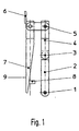
- a ramp according to the invention is shown in the "rest position" in which they e.g. not in a tram in the entrance area next to one here shown door.
- the ramp comprises a swivel joint 1, a first segment 2 (hereinafter Base platform called), a first hinge 3, a second segment 4, a second Hinge 5, a stop 6, a third segment 7, one only indicated here Lock 8 and one for easy attachment of information boards such as Operating information or advertising posters formed area 9.
- the base platform 2 is connected via the swivel joint 1 with one not shown Vehicle connected.
- the swivel joint 1 allows an adjustable rotation up to over 180 ° too.
- the segment 4 is connected to the base platform 2 via the hinge 3. about the hinge 5, the segment 7 is connected to the segment 4.
- the base platform 2 is in the example shown by 180 ° Swivel swivel joint 1 has been rotated.
- the segment 7 is around the hinge 5 to opened to stop 6. In this position the swivel joint can be pivoted.
- Fig. 4 shows the unfolded ramp.
- Fig. 5 shows purely schematically the process of unfolding one ramp according to the invention.
- 5 shows the ramp in the Rest position folded in the entrance area of a door.
- they are Segments 4 and 7 and the base platform 2 already partially unfolded.
- the base platform segment 4 and segment 7 are complete unfolded so that they are aligned.
- the platform finally folded to the vehicle floor by means of the swivel joint, so that the base platform rests on the vehicle floor, while the segments 4 and 7 point obliquely downwards from the base platform 2 to the floor, the Segment B on the floor, e.g. lies on a sidewalk.
- a special feature of the invention is in any case Articulation of the individual segments to one another such that the respective Swivel axes between the segments in the intended Assembled in the unfolded state in the direction of travel, which causes that a wide ramp in the folded state is longer, but not is wider than an otherwise equally large narrow ramp and therefore in collapsed condition does not hinder passage in a vehicle.
- the Flange point of the swivel joint at different points in the Vehicle can take place, that is, the distance to the exit edge can be of different lengths.
- the base platform can then according to the Vehicle conditions to be adjusted to the length.
- The can also Design the base platform to adjust the length at the side.
Abstract
Description
Die Erfindung betrifft eine ausschwenkbare Rampe für Fahrzeuge, insbesondere für Fahrzeuge für den Personennahverkehr, also Straßenbahnen, U-Bahnen, S-Bahnen, Busse, Züge und dergleichen.The invention relates to a swing-out ramp for vehicles, in particular for Vehicles for local public transport, i.e. trams, subways, S-Bahn, buses, trains and the like.
Solche Rampen sind bekannt. Sie werden bedarfsweise ausgefahren oder ausgeklappt, um so Rollstuhlfahrern oder kleineren Transportwägelchen die Zufahrt zu dem jeweiligen mit der Rampe versehenen Fahrzeug zu ermöglichen.Such ramps are known. If necessary, they are extended or unfolded in order to give wheelchair users or smaller transport carts access to the respective vehicle provided with the ramp.
Während motorisch betriebene Rampen weitestgehend automatisch ausfahren, müssen manuelle Rampen von einem Bediener (z.B. Fahrer oder einer Begleitperson) ausgefahren oder ausgeklappt werden.While motorized ramps extend largely automatically, manual ramps must be operated by an operator (e.g. driver or operator) Accompanying person) can be extended or unfolded.
Manuelle Rampen werden entweder als Bodendeckel ausgeklappt oder als seitlich angebrachte Rampe in den Eingangsbereich eingeschwenkt und dann in Position gebracht. Dabei haben seitlich angebrachte Rampen den Vorteil, daß deren Einbau keine oder allenfalls ganz geringe Veränderungen der Fahrzeugkonstruktion erfordert.Manual ramps are either folded out as a floor cover or as a side attached ramp swung into the entrance area and then in position brought. Ramps attached to the side have the advantage that their installation no or only very slight changes to the vehicle construction requires.
Aufgrund ihrer universellen Einsetzbarkeit, großen Zuverlässigkeit und aus Kostengründen haben sich seitlich im Eingangsbereich eines Fahrzeugs, nämlich links oder rechts neben einer aufschwenkbaren oder aufschiebbaren Tür angebrachte, manuell betätigbare Rampen durchgesetzt. Solche Rampen können auch bei bestehenden Fahrzeugen in verhältnismäßig einfacher Weise nachgerüstet werden.Because of their universal applicability, great reliability and out There are cost reasons laterally in the entrance area of a vehicle, namely left or right next to a swinging or sliding door attached, manually operated ramps enforced. Such ramps can even in existing vehicles in a relatively simple manner be retrofitted.
Die bekannten Rampen zur seitlichen Anordnung im Eingangsbereich eines Fahrzeugs sind über einen Schwenkhebel mit dem Fahrzeugboden verbunden. Im Ruhezustand stehen sie aufrecht im Eingangsbereich eines damit versehenen Fahrzeugs, also quasi wie eine nach innen geöffnete Tür, und werden in dieser Position von dem Schwenkhebel und gegebenenfalls vorgesehenen lösbaren Fixierungen gehalten. The known ramps for lateral arrangement in the entrance area of a Vehicles are connected to the vehicle floor via a swivel lever. in the In the idle state, they stand upright in the entrance area of an equipped one Vehicle, so to speak like a door opened inwards, and are in this Position of the pivot lever and, if applicable, provided detachable Fixations held.
Bei Benutzung werden sie zunächst um 90° geschwenkt, etwa so, als wollte man einen nach innen geöffneten Türflügel schließen, und dann derart nach außen geklappt, daß die dem Fahrzeug zugewandte Außenkante den Fahrzeugboden im Bereich der Tür nur in einem ganz geringen Maße überlappt und die Rampe im wesentlichen also von dem Schwenkhebel gehalten wird. Je nach Länge der Rampe (gesehen in Richtung des Ein- oder Ausstiegs in das Fahrzeug) und Höhe des Fahrzeuges wird die Rampe dabei um einen Winkel von typischerweise 125° bis 135° nach außen geklappt. Da solche Rampen im Regelfall aus zwei etwa gleich großen, an einer Längsseite aneinander angelenkten Blechen bestehen, müssen schließlich noch die beiden Bleche auseinander geklappt werden, so daß schließlich die beiden Bleche nebeneinander liegen und so eine in Auffahrrichtung in eine linke und rechte Hälfte geteilte Rampe von einer Straße bzw. von einem Bürgersteig in das Fahrzeug bilden.When in use, they are initially pivoted through 90 °, as if you wanted to close a door leaf that is open to the inside, and then to the outside folded that the vehicle's outer edge facing the vehicle floor in The area of the door only overlaps to a very small extent and the ramp in the essentially held by the pivot lever. Depending on the length of the Ramp (seen in the direction of entering or exiting the vehicle) and height the ramp of the vehicle is typically an angle of 125 ° folded up to 135 °. Since such ramps are usually roughly the same from two large, hinged to each other on one long side, must exist finally the two sheets are folded apart, so that finally the two sheets are next to each other and so one in the drive-up direction in a left and right half divided ramp from a street or sidewalk in form the vehicle.
Ein Problem bei diesen bekannten Rampen ist die konstruktionsbedingte beschränkte Breite (wiederum gesehen in Ein- oder Ausstiegsrichtung): die Rampen können nur eine verhältnismäßig beschränkte Breite aufweisen, da sie sonst im eingeklappten Zustand, in welchem sie etwa rechtwinklig zur Fahrtrichtung stehen, den Durchgang in der Fahrzeugrichtung behindern. Ein weiteres Problem ist die beschränkte Stabilität der Rampe aufgrund der nur geringen Auflagefläche der ausgeklappten Rampe auf dem Fahrzeugboden.One problem with these known ramps is that of design limited width (again seen in the entry or exit direction): the Ramps can only have a relatively limited width because they otherwise in the folded state, in which they are approximately at right angles to the direction of travel stand, obstruct the passage in the vehicle direction. Another Problem is the limited stability of the ramp due to the small contact area the unfolded ramp on the vehicle floor.
Davon ausgehend liegt der Erfindung die Aufgabe zugrunde, eine verbesserte ausklappbare Rampe für Fahrzeuge anzugeben.Based on this, the object of the invention is an improved one fold-out ramp to be specified for vehicles.
Die Aufgabe wird gelöst von einer Rampe gemäß Anspruch1. Einzelheiten und Vorteile der Rampe ergeben sich aus der nachfolgenden detaillierten Beschreibung eines Ausführungsbeispiels in Verbindung mit der Zeichnung, in welcher:
- Fig. 1
- eine schematische Darstellung einer erfindungsgemäßen Rampe im komplett eingeklappten Zustand (Ruheposition) in Draufsicht (gesehen in Richtung auf den Fahrzeugboden) zeigt,
- Fig. 2
- die Rampe gemäß Fig. 1 im ausgeklappten, jedoch noch nicht in Richtung auf den Fahrzeugboden geschwenkten Zustand in Draufsicht zeigt ,
- Fig. 3
- eine Draufsicht auf die Rampe gemäß Fig. 2 im in Richtung auf den Fahrzeugboden geschwenkten Zustand zeigt,
- Fig. 4
- eine Seitenansicht auf die komplett ausgeklappte, umgeschwenkte und in Richtung auf den Straßenboden abgeklappte Rampe (Arbeitsposition) zeigt und
- Fig. 5
- in vier Einzelfiguren (a) bis (d) schematisch den Ablauf des Ausklappens der Rampe von der Ruheposition in die Arbeitsposition zeigt.
- Fig. 1
- 1 shows a schematic illustration of a ramp according to the invention in the completely folded state (rest position) in a top view (viewed in the direction of the vehicle floor),
- Fig. 2
- 1 shows the ramp according to FIG. 1 in the unfolded state, but not yet pivoted in the direction of the vehicle floor, in a top view,
- Fig. 3
- 2 shows a top view of the ramp according to FIG. 2 in the state pivoted towards the vehicle floor,
- Fig. 4
- a side view of the completely unfolded, swung and folded towards the street floor ramp (working position) and
- Fig. 5
- in four individual figures (a) to (d) schematically shows the sequence of unfolding the ramp from the rest position to the working position.
In Fig. 1 ist eine erfindungsgemäße Rampe in der "Ruheposition" gezeigt, in welcher sie z.B. in einer Straßenbahn im Eingangsbereich neben einer hier nicht gezeigten Tür stünde.In Fig. 1 a ramp according to the invention is shown in the "rest position" in which they e.g. not in a tram in the entrance area next to one here shown door.
Die Rampe umfaßt ein Drehschwenkgelenk 1, ein erstes Segment 2 (nachfolgend
Basisplattform genannt), ein erstes Scharnier 3, ein zweites Segment 4, ein zweites
Scharnier 5, einen Anschlag 6, ein drittes Segment 7, eine hier nur angedeutete
Verriegelung 8 und eine zur leichten Anbringung von Hinweistafeln wie z.B.
Bedienungsinformationen oder Werbeplakaten ausgebildete Fläche 9.The ramp comprises a
Die Basisplattform 2 ist über das Drehschwenkgelenk 1 mit einem nicht gezeigten
Fahrzeug verbunden. Das Drehschwenkgelenk 1 läßt eine einstellbare Drehung bis
über 180° zu.The
Über das Scharnier 3 ist das Segment 4 mit der Basisplattform 2 verbunden. Über
das Scharnier 5 ist das Segment 7 mit dem Segment 4 verbunden.The
Eine nur angedeutete Verriegelung 8, z.B. in Form von Rastelementen, die mit
entsprechenden Elementen am Fahrzeug zusammenwirken können, dient zum
Fixieren der Rampe in der Ruhestellung, so daß sie auch in Fahrt sicher gehalten
ist.An only indicated
Die Fig. 2 zeigt die entriegelte und aufgeklappte senkrechte Stellung der Rampe.
Die Basisplattform 2 ist in dem dargestellten Beispiel um 180° um das
Drehschwenkgelenk 1 gedreht worden. Das Segment 7 ist um das Scharnier 5 bis
zum Anschlag 6 aufgeklappt. In dieser Position kann das Drehschwenkgelenk
geschwenkt werden.2 shows the unlocked and opened vertical position of the ramp.
The
In der in Fig. 3 gezeigten Stellung ist die Rampe soweit zum Fahrzeugboden
hingeschwenkt, daß die Basisplattform 2 komplett auf dem Fahrzeugfußboden
aufliegt. Die Basisplattform 2 kann in dieser Lage am Fahrzeugfußboden mittels
hier nicht weiter gezeigter Befestigungsmittel temporär fixiert werden, zum Beispiel
am in Fig. 3 bezeichneten "Befestigungspunkt".In the position shown in Fig. 3, the ramp is so far to the vehicle floor
pivoted that the
Fig. 4 zeigt die ausgeklappte Rampe. Man erkennt deutlich, daß sich die Segmente
4 und 7 um das Scharnier 3 bis zum Straßenniveau hin absenken können und somit
eine schräge Auffahrt in das Fahrzeug ermöglichen.Fig. 4 shows the unfolded ramp. One can clearly see that the
Die Fig. 5 zeigt rein schematisch den Ablauf des Ausklappens einer
erfindungsgemäßen Rampe. Im Bild (a) der Fig. 5 steht die Rampe in der
Ruheposition zusammengeklappt im Eingangsbereich einer Tür. Im Bild (b) sind die
Segmente 4 und 7 und die Basisplattform 2 bereits teilweise auseinandergefaltet.
Im Bild (c) sind die Basisplattform, das Segment 4 und das Segment 7 komplett
auseinandergefaltet, so daß sie miteinander fluchten. Im Bild (d) ist die Plattform
schließlich mittels des Drehschwenkgelenkes zum Fahrzeugboden hin geklappt, so
daß die Basisplattform auf dem Fahrzeugboden aufliegt, während die Segmente 4
und 7 von der Basisplattform 2 schräg nach unten zum Boden weisen, wobei das
Segment B auf dem Boden, also z.B. einem Bürgersteig aufliegt.Fig. 5 shows purely schematically the process of unfolding one
ramp according to the invention. 5 shows the ramp in the
Rest position folded in the entrance area of a door. In picture (b) they are
Wie in Fig. 5 gut zu erkennen, sind die beiden Segmente 4 und 7, die die
eigentliche Auffahrfunktion im ausgeklappten Zustand erfüllen, im ausgeklappten
Zustand in Fahrtrichtung geteilt, während die bislang bekannten Rampen wie oben
beschrieben in Einstiegsrichtung geteilt sind. 5, the two
Die rein beispielhaft und nicht-beschränkend dargestellte Rampe zeichnet sich unter anderem dadurch aus,
- daß sie über die als Trägereinheit wirkende stabile Basisplattform sehr leicht bedienbar ist;
- daß die Basisplattform das einzige Element, das auf die fahrzeugspezifischen Einbauverhältnisse (Abstand Drehschwenkgelenk zur Fußbodenaußenkante) angepaßt werden muß, während für die anderen Teile Standardteile verwendet werden können;
- daß die Basisplattform mit dem Fahrzeugfußboden oder der Fahrzeugseitenwand lediglich über ein Dreh-Schwenkgelenk verbunden ist;
- daß über das Dreh-Schwenkgelenk die gewünschte Bewegung der Rampe von einer senkrechten in eine horizontale Lage durch manuelle Unterstützung leicht erbracht werden kann;
- daß die Basisplattform in der ausgeklappten Stellung durch geeignete, an die jeweiligen Fahrzeugverhältnisse angepaßte Mittel sicher in Position gehalten wird;
- daß sie problemlos an entsprechenden Fahrzeug nachgerüstet werden kann und bei Bedarf schnell demontierbar ist;
- daß die Unterseite des
Segmentes 7 in der eingeklappten Ruheposition zur Anbringung von Bedien- oder sonstigen Hinweisen genutzt werden kann; daß das Segment 7 mit seitlichen Erhöhungen ausgeführt werden kann, die ein seitliches Abrollen eines Rollstuhls oder eines Transportwagens sicher verhindern, wobei solche seitlichen Erhöhungen im eingeklappten Ruhezustand vorteilhaft als obere und untere Abdeckung der Rampe dienen;- daß die
Segmente 4 und 7 durch Anschläge gegen ein ungewolltes Durchknicken geschützt sind; und - daß Ausklapplänge und Einfahrbreite leicht an die jeweiligen Kundenwünsche angepaßt werden können.
- that it is very easy to operate via the stable base platform acting as a carrier unit;
- that the base platform is the only element that has to be adapted to the vehicle-specific installation conditions (distance of the swivel joint to the outer edge of the floor), while standard parts can be used for the other parts;
- that the base platform is connected to the vehicle floor or the vehicle side wall only via a swivel joint;
- that the desired movement of the ramp from a vertical to a horizontal position can be easily achieved by manual support via the rotary swivel joint;
- that the base platform is held securely in position in the unfolded position by suitable means adapted to the respective vehicle conditions;
- that it can be easily retrofitted to the corresponding vehicle and can be quickly dismantled if required;
- that the underside of the
segment 7 can be used in the folded rest position for attaching operating or other information; - that the
segment 7 can be carried out with side elevations which reliably prevent a wheelchair or a trolley from rolling sideways, such side elevations advantageously serving as the upper and lower cover of the ramp in the retracted idle state; - that the
segments - that the fold-out length and drive-in width can easily be adapted to the respective customer requirements.
Im Rahmen des Erfindungsgedankens sind zahlreiche Abwandlungen und Weiterbildungen möglich. Eine Besonderheit der Erfindung ist jedenfalls die Anlenkung der einzelnen Segmente aneinander derart, daß die jeweiligen Schwenkachsen zwischen den Segmenten im bestimmungsgemäßen Montagezustand im ausgeklappten Zustand in Fahrtrichtung verlaufen, was bewirkt, daß eine breite Rampe im zusammengeklappten Zustand zwar länger, aber nicht breiter ist als eine ansonsten gleichgroße schmale Rampe und daher im zusammengeklappten Zustand den Durchgang in einem Fahrzeug nicht behindert.Within the framework of the inventive concept, numerous modifications and Further training possible. A special feature of the invention is in any case Articulation of the individual segments to one another such that the respective Swivel axes between the segments in the intended Assembled in the unfolded state in the direction of travel, which causes that a wide ramp in the folded state is longer, but not is wider than an otherwise equally large narrow ramp and therefore in collapsed condition does not hinder passage in a vehicle.
Eine weitere Besonderheit ist, daß durch die Verwendung der Basisplattform der Anflanschpunkt des Dreh-Schwenkgelenkes an unterschiedlichen Stellen im Fahrzeug erfolgen kann, das heißt, daß der Abstand zur Ausstiegskante unterschiedlich lang sein kann. Die Basisplattform kann dann entsprechend der Fahrzeugverhältnisse auf die Länge angepaßt werden. Ebenfalls kann die Gestaltung der Basisplattform den seitlichen Längenausgleich vornehmen. Durch entsprechende Ausgestaltung der einzelnen Elemente der Plattform und insbesondere der Seitenbereiche der Basisplattform der weiteren Segmente, kann die Rampe im zusammengeklappten Zustand eine Einheit bilden, die keiner weiteren Abdeckung etwa durch eine Tasche oder einen Schutzüberzug bedarf und bei der trotzdem versehentliche Quetschungen oder dergleichen sicher ausgeschlossen sind.Another peculiarity is that by using the basic platform the Flange point of the swivel joint at different points in the Vehicle can take place, that is, the distance to the exit edge can be of different lengths. The base platform can then according to the Vehicle conditions to be adjusted to the length. The can also Design the base platform to adjust the length at the side. By appropriate design of the individual elements of the platform and especially the side areas of the base platform of the other segments the ramp in the folded state form a unit that none further coverage such as a bag or a protective cover is required and in the event of accidental bruising or the like excluded are.
Claims (8)
dadurch gekennzeichnet, daß die Segmente (2, 4, 7) derart aneinander angelenkt sind, daß die jeweiligen Schwenkachsen zwischen den Segmenten im bestimmungsgemäßen Montagezustand im ausgeklappten Zustand in Fahrtrichtung verlaufen.Swing-out ramp for vehicles, in particular for vehicles for local public transport, with at least two segments (2, 4, 7) which are essentially rectangular in plan view, one (2) of which is articulated to a vehicle in the intended installation state,
characterized in that the segments (2, 4, 7) are articulated to one another in such a way that the respective pivot axes between the segments run in the direction of travel in the unfolded state in the intended assembly state.
dadurch gekennzeichnet, daß die Rampe aus drei Segmenten (2, 4, 7) besteht, von denen eines eine Basisplattform (2) bildet, die über eine Drehschwenkgelenk (1) mit dem Fahrzeugboden oder einer Fahrzeugseite verbunden werden kann und an deren einer Längsseite ein zweites Segment (4) angelenkt ist, an dessen der Basisplattform gegenüberliegender Längsseite das dritte Segment (7) angelenkt ist.Ramp according to claim 1,
characterized in that the ramp consists of three segments (2, 4, 7), one of which forms a base platform (2) which can be connected to the vehicle floor or one side of the vehicle via a swivel joint (1) and one on the long side of which second segment (4) is articulated, on whose longitudinal side opposite the base platform the third segment (7) is articulated.
dadurch gekennzeichnet, daß eines der Segmente (2) derart um ein Drehschwenkgelenk (1) schwenkbar ist, das es in einer Ruheposition aufrecht im Eingangsbereich einer Fahrzeugtür stehen kann und in einer Arbeitsposition flach auf dem Fahrzeugboden anliegt.Ramp according to claim 1 or 2,
characterized in that one of the segments (2) can be pivoted about a swivel joint (1) in such a way that in a rest position it can stand upright in the entrance area of a vehicle door and in a working position lies flat on the vehicle floor.
dadurch gekennzeichnet, daß zwei Segmente (4, 7) derart an einem dritten Segment (2) angelenkt sind, daß sie im Ruhezustand aufrecht im Eingangsbereich eines Fahrzeugs stehen können und im Benutzungszustand eine von dem dritten Segment abgewinkelte schräge Auffahrt bilden. Ramp according to one of claims 1 to 3,
characterized in that two segments (4, 7) are articulated to a third segment (2) in such a way that they can stand upright in the entrance area of a vehicle in the idle state and form an inclined driveway angled from the third segment in the use state.
dadurch gekennzeichnet, daß Mittel zum Sichern eines der Segmente (2) in der ausgeklappten Stellung am Fahrzeugboden vorgesehen sind.Ramp according to one of claims 1 to 4,
characterized in that means for securing one of the segments (2) are provided in the unfolded position on the vehicle floor.
dadurch gekennzeichnet,
characterized,
dadurch gekennzeichnet,
characterized,
dadurch gekennzeichnet,
characterized,
Applications Claiming Priority (2)
| Application Number | Priority Date | Filing Date | Title |
|---|---|---|---|
| DE10306526 | 2003-02-14 | ||
| DE10306526 | 2003-02-14 |
Publications (2)
| Publication Number | Publication Date |
|---|---|
| EP1447272A2 true EP1447272A2 (en) | 2004-08-18 |
| EP1447272A3 EP1447272A3 (en) | 2005-04-20 |
Family
ID=32668091
Family Applications (1)
| Application Number | Title | Priority Date | Filing Date |
|---|---|---|---|
| EP04003257A Withdrawn EP1447272A3 (en) | 2003-02-14 | 2004-02-13 | Deployable ramp for vehicles |
Country Status (2)
| Country | Link |
|---|---|
| EP (1) | EP1447272A3 (en) |
| DE (1) | DE102004007496A1 (en) |
Cited By (10)
| Publication number | Priority date | Publication date | Assignee | Title |
|---|---|---|---|---|
| WO2008113310A1 (en) * | 2007-03-22 | 2008-09-25 | Reiner Wagner | Swing-out wheelchair ramp for railway vehicles |
| US7533432B2 (en) | 2007-05-04 | 2009-05-19 | Lift-U, Division Of Hogan Mfg., Inc. | Counterbalance assembly for a fold out ramp |
| US7870631B2 (en) | 2008-05-02 | 2011-01-18 | Lift-U, Division Of Hogan Mfg., Inc. | Fold out ramp |
| WO2011051522A3 (en) * | 2009-10-06 | 2011-08-11 | Gueell Perpinya Francisco Javier | Clip-assembled, weld-free folding or fixed ramp for overcoming changes in level |
| US8122553B1 (en) | 2011-01-27 | 2012-02-28 | Lift-U, Division Of Hogan Mfg., Inc. | Fold out ramp |
| US8230539B2 (en) | 2007-05-04 | 2012-07-31 | Lift-U, Division Of Hogan Mfg., Inc. | Fold out ramp |
| US8250693B1 (en) | 2011-01-27 | 2012-08-28 | Lift-U, Division Of Hogan Mfg., Inc. | Fold out ramp |
| US8359691B2 (en) | 2007-02-01 | 2013-01-29 | Lift-U, Division Of Hogan Mfg., Inc. | Compact folding slide-out ramp assembly |
| US8375496B1 (en) | 2011-01-27 | 2013-02-19 | Lift-U, Division Of Hogan Mfg., Inc. | Fold out ramp |
| EP2489568A3 (en) * | 2011-02-21 | 2013-04-10 | Siemens Aktiengesellschaft | Ramp with mechanically variable fixing |
Families Citing this family (4)
| Publication number | Priority date | Publication date | Assignee | Title |
|---|---|---|---|---|
| DE102009017247A1 (en) | 2009-04-09 | 2010-10-14 | Reiner Wagner | Swing-out wheelchair ramp for railway vehicles parallel to the vehicle wall |
| DE202009005503U1 (en) | 2009-04-09 | 2009-07-16 | Wagner, Reiner | Swing-out wheelchair ramp for railway vehicles parallel to the vehicle wall |
| DE102019204766A1 (en) * | 2019-04-03 | 2020-10-08 | Volkswagen Aktiengesellschaft | Vehicle with a ramp arrangement |
| DE102020212484B3 (en) | 2020-10-02 | 2021-07-08 | Volkswagen Aktiengesellschaft | Support structure for a vehicle and vehicle with such |
Citations (4)
| Publication number | Priority date | Publication date | Assignee | Title |
|---|---|---|---|---|
| US4966516A (en) * | 1988-11-23 | 1990-10-30 | Vartanian Industries, Inc. | Vehicle access ramp having alternative pivots for stowing |
| US5259081A (en) * | 1991-02-19 | 1993-11-09 | James Henderson | Portable wheel chair ramp and restraining device |
| US5871329A (en) * | 1997-05-21 | 1999-02-16 | U.S. Vantage Company Llc | Powered wheelchair ramp for minivans |
| US6293748B1 (en) * | 2000-06-13 | 2001-09-25 | Pierre Savaria | Storable ramp assembly |
-
2004
- 2004-02-13 EP EP04003257A patent/EP1447272A3/en not_active Withdrawn
- 2004-02-13 DE DE200410007496 patent/DE102004007496A1/en not_active Withdrawn
Patent Citations (4)
| Publication number | Priority date | Publication date | Assignee | Title |
|---|---|---|---|---|
| US4966516A (en) * | 1988-11-23 | 1990-10-30 | Vartanian Industries, Inc. | Vehicle access ramp having alternative pivots for stowing |
| US5259081A (en) * | 1991-02-19 | 1993-11-09 | James Henderson | Portable wheel chair ramp and restraining device |
| US5871329A (en) * | 1997-05-21 | 1999-02-16 | U.S. Vantage Company Llc | Powered wheelchair ramp for minivans |
| US6293748B1 (en) * | 2000-06-13 | 2001-09-25 | Pierre Savaria | Storable ramp assembly |
Cited By (18)
| Publication number | Priority date | Publication date | Assignee | Title |
|---|---|---|---|---|
| US8505141B1 (en) | 2007-02-01 | 2013-08-13 | Lift-U, Division Of Hogan Mfg., Inc. | Compact folding slide-out ramp assembly |
| US8359691B2 (en) | 2007-02-01 | 2013-01-29 | Lift-U, Division Of Hogan Mfg., Inc. | Compact folding slide-out ramp assembly |
| WO2008113310A1 (en) * | 2007-03-22 | 2008-09-25 | Reiner Wagner | Swing-out wheelchair ramp for railway vehicles |
| US8032963B2 (en) | 2007-05-04 | 2011-10-11 | Lift-U, A Division Of Hogan Mfg., Inc. | Fold out ramp |
| US8230539B2 (en) | 2007-05-04 | 2012-07-31 | Lift-U, Division Of Hogan Mfg., Inc. | Fold out ramp |
| US7870630B2 (en) | 2007-05-04 | 2011-01-18 | Lift-U, Division Of Hogan Mfg., Inc. | Articulating close out assembly for a fold out ramp |
| US7533433B2 (en) | 2007-05-04 | 2009-05-19 | Lift-U, Division Of Hogan Mfg., Inc. | Counterbalance assembly for a fold out ramp |
| US7533432B2 (en) | 2007-05-04 | 2009-05-19 | Lift-U, Division Of Hogan Mfg., Inc. | Counterbalance assembly for a fold out ramp |
| US7681272B2 (en) | 2007-05-04 | 2010-03-23 | Lift-U, Division Of Hogan Mfg. | Counterbalance assembly for a fold out ramp |
| US7533434B2 (en) | 2007-05-04 | 2009-05-19 | Lift-U, Division Of Hogan, Mfg., Inc. | Counterbalance assembly for a fold out ramp |
| US7870631B2 (en) | 2008-05-02 | 2011-01-18 | Lift-U, Division Of Hogan Mfg., Inc. | Fold out ramp |
| WO2011051522A3 (en) * | 2009-10-06 | 2011-08-11 | Gueell Perpinya Francisco Javier | Clip-assembled, weld-free folding or fixed ramp for overcoming changes in level |
| US8132281B1 (en) | 2011-01-27 | 2012-03-13 | Lift-U, Division Of Hogan Mfg., Inc. | Fold out ramp |
| US8250693B1 (en) | 2011-01-27 | 2012-08-28 | Lift-U, Division Of Hogan Mfg., Inc. | Fold out ramp |
| US8181300B1 (en) | 2011-01-27 | 2012-05-22 | Lift-U, Division Of Hogan Mfg., Inc. | Fold out ramp |
| US8375496B1 (en) | 2011-01-27 | 2013-02-19 | Lift-U, Division Of Hogan Mfg., Inc. | Fold out ramp |
| US8122553B1 (en) | 2011-01-27 | 2012-02-28 | Lift-U, Division Of Hogan Mfg., Inc. | Fold out ramp |
| EP2489568A3 (en) * | 2011-02-21 | 2013-04-10 | Siemens Aktiengesellschaft | Ramp with mechanically variable fixing |
Also Published As
| Publication number | Publication date |
|---|---|
| DE102004007496A1 (en) | 2004-09-23 |
| EP1447272A3 (en) | 2005-04-20 |
Similar Documents
| Publication | Publication Date | Title |
|---|---|---|
| EP2907921B1 (en) | Barrier system | |
| EP1447272A2 (en) | Deployable ramp for vehicles | |
| EP3501467A1 (en) | Motor vehicle comprising a sliding door | |
| DE2620683C3 (en) | Entrance arrangement for a local transport vehicle, in particular a rail vehicle | |
| DE102007022387B4 (en) | Entry and exit aid for passenger transport vehicles | |
| DE102018105573A1 (en) | LIFTING STATION FOR MOTOR VEHICLES | |
| EP1669231A2 (en) | Sliding and folding door for automotive vehicles | |
| EP2030831A2 (en) | Military vehicle for transporting personnel | |
| DE202004002343U1 (en) | Folding ramp for bus or tram entrance, assembled of three segments and stored vertically | |
| DE4123456B4 (en) | Openable front wall for closed double-decker rail freight cars | |
| DE202007006863U1 (en) | Vehicle e.g. tramway, boarding and deboarding aid for use by handicapped human, has bridging panel formed as part of surface of vehicle base, and loaded surface between horizontal axis of rotation of rear ramp part and cartridge opening | |
| EP3558731B1 (en) | Rear door of bodies of lorries or lorry trailers | |
| DE4202622C2 (en) | Transportable container with changeable usable area | |
| EP3838668A1 (en) | Mobile enclosed space | |
| DE4200734A1 (en) | Roof construction for minibus-type touring vehicle - uses two=part second roof with tent section clamped to rainwater gutters | |
| EP0827856A1 (en) | Bus for sightseeing tours, especially single or double decker | |
| DE3903756C1 (en) | Apparatus for securing the transportation path between a building and a vehicle by movable shielding walls | |
| DE102011005238B4 (en) | Lockable ramp | |
| DE202006012590U1 (en) | Sales trolley e.g. sales trailer, for providing goods in market place, has supporting post fixedly connected with roof extension that runs parallel to long sides of fixed roof surface from guide up to end point | |
| DE19711356A1 (en) | Folding garage for vehicle | |
| DE102019135081A1 (en) | Vehicle door construction with integrated ramp | |
| DE202009005503U1 (en) | Swing-out wheelchair ramp for railway vehicles parallel to the vehicle wall | |
| DE102009017247A1 (en) | Swing-out wheelchair ramp for railway vehicles parallel to the vehicle wall | |
| EP3875338A1 (en) | Door device for a car body of a passenger transport vehicle and passenger transport vehicle | |
| DE202014100949U1 (en) | Commercial vehicle with at least one side tarpaulin |
Legal Events
| Date | Code | Title | Description |
|---|---|---|---|
| PUAI | Public reference made under article 153(3) epc to a published international application that has entered the european phase |
Free format text: ORIGINAL CODE: 0009012 |
|
| AK | Designated contracting states |
Kind code of ref document: A2 Designated state(s): AT BE BG CH CY CZ DE DK EE ES FI FR GB GR HU IE IT LI LU MC NL PT RO SE SI SK TR |
|
| AX | Request for extension of the european patent |
Extension state: AL LT LV MK |
|
| PUAL | Search report despatched |
Free format text: ORIGINAL CODE: 0009013 |
|
| AK | Designated contracting states |
Kind code of ref document: A3 Designated state(s): AT BE BG CH CY CZ DE DK EE ES FI FR GB GR HU IE IT LI LU MC NL PT RO SE SI SK TR |
|
| AX | Request for extension of the european patent |
Extension state: AL LT LV MK |
|
| RIC1 | Information provided on ipc code assigned before grant |
Ipc: 7E 04F 11/00 B Ipc: 7B 60P 1/43 B Ipc: 7B 60R 3/00 B Ipc: 7A 61G 3/06 A |
|
| 17P | Request for examination filed |
Effective date: 20051017 |
|
| AKX | Designation fees paid |
Designated state(s): AT BE BG CH CY CZ DE DK EE ES FI FR GB GR HU IE IT LI LU MC NL PT RO SE SI SK TR |
|
| STAA | Information on the status of an ep patent application or granted ep patent |
Free format text: STATUS: THE APPLICATION IS DEEMED TO BE WITHDRAWN |
|
| 18D | Application deemed to be withdrawn |
Effective date: 20060720 |