EP1447197B1 - Laufflächenformwerkzeug zum Formen einer ringförmigen Lauffläche - Google Patents
Laufflächenformwerkzeug zum Formen einer ringförmigen Lauffläche Download PDFInfo
- Publication number
- EP1447197B1 EP1447197B1 EP04002544A EP04002544A EP1447197B1 EP 1447197 B1 EP1447197 B1 EP 1447197B1 EP 04002544 A EP04002544 A EP 04002544A EP 04002544 A EP04002544 A EP 04002544A EP 1447197 B1 EP1447197 B1 EP 1447197B1
- Authority
- EP
- European Patent Office
- Prior art keywords
- segments
- tread
- mold
- segment
- radially
- Prior art date
- Legal status (The legal status is an assumption and is not a legal conclusion. Google has not performed a legal analysis and makes no representation as to the accuracy of the status listed.)
- Expired - Lifetime
Links
- 238000000465 moulding Methods 0.000 title claims description 5
- 229920001971 elastomer Polymers 0.000 description 13
- 230000000712 assembly Effects 0.000 description 4
- 238000000429 assembly Methods 0.000 description 4
- 230000002787 reinforcement Effects 0.000 description 3
- 230000001154 acute effect Effects 0.000 description 2
- 239000012530 fluid Substances 0.000 description 2
- 238000010438 heat treatment Methods 0.000 description 2
- 230000007246 mechanism Effects 0.000 description 2
- 239000002184 metal Substances 0.000 description 2
- 238000007789 sealing Methods 0.000 description 2
- 239000011324 bead Substances 0.000 description 1
- 150000001875 compounds Chemical class 0.000 description 1
- 230000006835 compression Effects 0.000 description 1
- 238000007906 compression Methods 0.000 description 1
- 230000001419 dependent effect Effects 0.000 description 1
- 238000006073 displacement reaction Methods 0.000 description 1
- 239000000806 elastomer Substances 0.000 description 1
- 239000004744 fabric Substances 0.000 description 1
- 230000014759 maintenance of location Effects 0.000 description 1
- 239000000463 material Substances 0.000 description 1
- 230000002028 premature Effects 0.000 description 1
Images




Classifications
-
- B—PERFORMING OPERATIONS; TRANSPORTING
- B29—WORKING OF PLASTICS; WORKING OF SUBSTANCES IN A PLASTIC STATE IN GENERAL
- B29D—PRODUCING PARTICULAR ARTICLES FROM PLASTICS OR FROM SUBSTANCES IN A PLASTIC STATE
- B29D30/00—Producing pneumatic or solid tyres or parts thereof
- B29D30/06—Pneumatic tyres or parts thereof (e.g. produced by casting, moulding, compression moulding, injection moulding, centrifugal casting)
- B29D30/0601—Vulcanising tyres; Vulcanising presses for tyres
-
- B—PERFORMING OPERATIONS; TRANSPORTING
- B29—WORKING OF PLASTICS; WORKING OF SUBSTANCES IN A PLASTIC STATE IN GENERAL
- B29D—PRODUCING PARTICULAR ARTICLES FROM PLASTICS OR FROM SUBSTANCES IN A PLASTIC STATE
- B29D30/00—Producing pneumatic or solid tyres or parts thereof
- B29D30/06—Pneumatic tyres or parts thereof (e.g. produced by casting, moulding, compression moulding, injection moulding, centrifugal casting)
- B29D30/52—Unvulcanised treads, e.g. on used tyres; Retreading
- B29D30/54—Retreading
- B29D30/56—Retreading with prevulcanised tread
Definitions
- the present invention relates to a segmented annular tread mold for curing an annular ring tread, according to the pre-characterizing part of claim 1.
- US-A- 4,207,052 on which the pre-characterizing part of claim 1 is based shows a plurality of inner segments which fit together to form a generally cylindrical mold face surface to form the inner surface of the tread belt along with a means for retracting said plurality of inner segments toward the axis of said inner cylinder and a means for heating said segments.
- the apparatus included a plurality of outer segments which fit together to form an inner generally cylindrical mold face surface of an outer cylinder, said outer cylinder being coaxial with said inner cylinder and of equal lengths therewith along with the means for retracting the plurality of outer segments away from the common axis of said cylinders and a means for heating said plurality of outer segments.
- the apparatus further included a pair of rings for sealing said inner cylinder to said outer cylinder at the ends thereof, at least one of said sealing rings being removable so that an uncured tire tread or track belt could be positionable between said plurality of inner segments and said plurality of outer segments wherein said plurality of inner segments was retracted toward said common axis and said plurality of outer segments is retracted away from said common axis.
- the radially retractable segments In the prior art it was common for the radially retractable segments to have curved or arcuate shapes with vertically extending edges or sides.
- the outer segments could move inwardly and create an annular ring for forming the outer tread surface including the tread lugs.
- the inner segments would move sequentially radially outwardly in an alternating pattern wherein every other inner tread segment would be extended and then every other retracted inner tread segment could be then extended outwardly thereby forming a ring in the fully extended position thereby providing a mold that would cure the tread belt assembly over a period of time. This time was considered the mold cure cycle.
- Each radially outer segment and each radially inner segment had edges that were generally vertically extending and parallel to the common axis of both the inner and outer segments.
- the inner segments Upon curing the tread the inner segments would then be retracted such that the inner surface of the molded tread could be separated from the first radially inward moving segments while the adjacent inner segments held in the closed position would retrain the tread belt assembly within the tread forming outer segments.
- the second set of radially inner segments could be moved inwardly thereby releasing the entire inner surface of the tread.
- the outer tread forming segments could be moved radially outwardly thereby releasing the tread belt assembly from the mold in its entirety. As the tread is removed from the outer segments a device would be used to lift the cured tread belt assembly from the mold.
- a second objective of the present invention is to provide a way in which the radially outer mold segments can be provided with improved structural integrity wherein the parting line between circumferentially adjacent segments extends across the tread lug forming depressions within the outer segments thereby avoiding thin ribs within the groove forming section of the mold to as large an extent as possible.
- the invention relates to an annular mold for curing an annular ring tread according to claim 1.
- the radially outer segments have inclined laterally extending edges relative to the axial direction of the mold while the circumferentially extending axially outer edges are perpendicular to the axial direction of the mold.
- the inclined laterally extending edges are inclined at least 5°, more preferably 10° relative to the axial direction.
- the mold has 12 outer segments, each segment being of an arc length of 30°.
- the radially outer segments each have a pair of obtuse angles ⁇ and a pair of acute angles ⁇ .
- the sum of ⁇ and ⁇ equal 180°, the sum of the pairs of ⁇ and ⁇ equal 360°.
- the mold when placed in a closed position has an annular shape, the outer segments forming an annular ring radially outward of the ring formed by the radially inner segments.
- the annular mold has an axis and a midcircumferential center plane perpendicular to the axis.
- the mold has a plurality of radially movable outer segments each movable outer segment being an arcuate parallelogram having pairs of obtuse included angles ⁇ and acute included angles ⁇ relative to the axis of the mold.
- the outer segments when closed form an annular ring of arcuately adjacent parallelograms.
- each axially outer segment has two inclined axially extending edges or surfaces.
- the inclined axially extending edges or surfaces are inclined relative to the axial direction. Furthermore, the arcuate circumferentially extending axially outer edges of the tread forming outer segments are preferably perpendicular to the axis of the mold.
- the combination of inner segments and outer segments provide a structurally improved mold design such that the arcuately shaped axially extending inclined outer edge surfaces extend beyond the radially inner segments such that the axially outer segments press against and have an inward force extending across one full axially inner segment and portions of two axially outer segments.
- the axially inclined edge surfaces of the outer segments extend across tread element forming depressions in each of the outer segments wherein the outer segments form circumferentially offset tread elements with respect to the mid-circumferential center plane of the mold and the linearly axially inclined surfaces extend nonparallel to the axis of the mold across circumferentially offset tread forming depressions within the outer segment.
- the tread element forming depressions can be elongated tread bars extending axially inwardly from the lateral edges of the mold toward the tread centerline.
- the tread element forming depression can include a circumferentially centered continuous rib forming depression.
- “Circumferential” means lines or directions extending along the perimeter of the surface of the annular tread perpendicular to the axial direction.
- Core means one of the reinforcement strands of which the plies in the track are comprised.
- Equatorial plane means the plane perpendicular to the track's axis of rotation and passing through the center of its tread.
- “Footprint” means the contact patch or area of contact of the tread with a flat surface under load and pressure.
- “Lateral” and “laterally” means lines or directions that are parallel to the axis of rotation of the tire (also “axial”).
- Ply means a continuous layer of rubber-coated parallel cords.
- Ring and radially means directions extending radially toward or away from the axis of rotation of the track.
- Zero-degree wires means at least one layer of parallel cords &usually metal wire), underlying the tread, unanchored to the bead, spiraling circumferentially around the tread, and having cord angles in the range from 0 degrees to 5 degrees with respect to the equatorial plane of the tire.
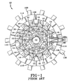
- Prior art tire tread and track belt curing apparatus 10 shown generally in Figures 1, 2 and 3 details the structure of said prior art apparatus 10.
- the apparatus 10 included an inner cylinder 12 formed of a first set of a plurality of inner segments 14, a second set of a plurality of inner segments 16 which act as slave segments which are carried forward by the movement of the first set of inner segments 14, which segments 14 are powered.
- the first set of segments 14 and the second set of segments 16 fit together in alternating sequence to form the inner cylinder 12. It is necessary that the inner cylinder 12 be completely continuous.
- gaps cannot be left between adjacent inner segments 14 and 16, and a proper mechanical arrangement must be provided to give an easy and smooth working mechanism whereby the first plurality of inner segments 14 and the second plurality of inner segments 16 can be easily retracted and advanced to form the continuous inner cylinder 12.
- Retraction of the first set of segments 14 proceeds via action of a first plurality of links 20 under the impetus of an elevation cylinder 22 which is moved upwardly or downwardly under the impetus of a first hydraulic cylinder.
- the first hydraulic cylinder acts between a frame and the elevation cylinder to cause the elevation cylinder 22 to move upwardly or downwardly as guided by a centering slide which forms a part of the frame.
- Each of the links 20 is pivoted at a plurality of first pivots 32 to the elevation cylinder 22.
- the elevation cylinder 22 is at its lowermost position under the impetus of the hydraulic cylinder which is substantially fully retracted and in that position each of the first plurality of links 20 and the second plurality of links 30 is substantially horizontal thus holding the first powered set of segments 14 in their outwardly expanded position to form the continuous inner cylinder 12.
- the outer cylinder 44 comprises a plurality of outer segments 106, each of which is retractable outwardly under the impetus of a respective one of a plurality of outer hydraulic cylinders 108, with each of the plurality of outer segments 106 being generally carried by a rod 110 of a respective one of the outer hydraulic cylinders 108, and with each of the segments of the plurality of outer segments 106 being slidingly held and positioned between a respective guide supported by the frame.
- US-A- 4,207,052 should be made.
- Each of the outer cylinders 108 is held by an outer ring portion 114 of the frame to form a continuous cylindrical ring as shown in Figure 3.
- the outer segments 106 each contain a portion 109 of the tread pattern for the tread belt or track assembly.
- Each portion of the outer segments 106 has a pair of vertical ends 107 that are radially parallel to the axis of the prior art mold 10.
- each outer segment 106 when viewed from the top has a circumferentially extending arcuately shaped top and bottom that are equal in length and aligned.
- This prior art mold design required the segment parting lines at the ends 107 to cross over the groove forming ribs 111 of the tread forming outer segments 106 and the outer cylinder 44 and the inner cylinder 12 would sandwich the tread belt assembly in between the inner cylinder 12 and outer cylinder 44 causing a compression on the assembly.
- the segments were heated with steam passing through passages in the mold to cure the tread belt assembly.
- Each inner segment 14, 16 and each outer segment 106 is held in abutting relation to the circumferentially adjacent segment.
- the outer segments 106 inwardly press radially against the tread and the inner segments 14, 16. During curing the retention of the segments in a fully closed position is critical.
- the present invention as illustrated in Figures 4 through 11 shows an improved mold curing apparatus for tread belt assemblies.
- inner segments of the present invention are employed that advance and retract in an alternating sequence.
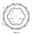
- the first set of inner segments 120A are arcuately shaped with the abutting edges 122 flared outwardly as shown.
- the second set of segments 120B have the abutting edges 121 flared inwardly as illustrated, thus when the first set of inner segments 120A is extended to a closed molding position as shown in Figure 5, the second set of inner segments can wedge the abutting edges 121 against the surfaces of the abutting edges 122 of the first inner segments 122 forming the inner ring as shown in Figure 6.
- the tread forming outer segments 130 press into the tread rubber forcing the tread rubber to move into the tread forming depressions.
- the groove forming ribs 155 on the mold surface 151 first engage the uncured rubber and push into the rubber. This movement requires a large amount of force but care must be exercised not to move the outer segments 130 too quickly into the tread belt so as to distort the underlying cord reinforcements or to close too slowly as to permit large amounts of rubber to get entrapped between the adjacent outer segments 130 in the area commonly referred to as the mold parting lines or to prematurely cure the rubber.
- the uncured tread belt 2 can be contoured to facilitate displacement of the tread rubber into the mold.
- the rubber was thicker in the center and then thinner at the lateral edges.
- the first tread belt formed from a mold according to the present invention, had a circumference of 11.132 m (438.25 inches) and a diameter of 3.543 m (139.5 inches).
- In cross section at the center tread belt assembly had a thickness of 15.75 cm (6.2 inches) that tapered to about 13.72 cm (5.4 inches) at the lateral edges. This is very complimentary to the tread forming outer segments contoured lateral edges and insures the tread rubber uniformly flows toward the lateral edges.
- the heated mold then cures at a pressure of about 27.6 bar (400 psi) for several hours.
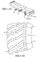
- the tread belt as shown in Figure 12 weighs over 2041 kg (4500 pounds).
- the outer segments 130 number twelve. This number can be larger or smaller depending on the tread belt size.
- Each outer segment 130 extends circumferentially in an arc of 30°. Unlike the prior art, however, this 30° arcuate parallelogram is inclined at an angle ⁇ relative to an axial direction.
- the outer segments 130 are inclined such that ⁇ is about 10°. Accordingly, the top of the outer segment 130 is shifted right 10° as the bottom is shifted toward the left 10° relative to the mold centerline. This effectively means that the outer segment 130 spans circumferentially about 50° from top to bottom.
- This inclination ⁇ is preferably 5° or greater.
- each outer segment 130 can align with at least two inner segments 120A, 120B.
- each outer segment can align with one full inner segment 120A or 120B and portions of two other inner segments 120A or 120B when the mold is fully closed.
- the pressure exerted by the closing of the outer segments 130 is absorbed more efficiently, particularly the second set of wedge shaped inner segments 120A or 120B receive mechanical support in that at least one, preferably both, inner segments 120A of the first set or the second set are partially aligned with an inclined parallelogram shaped outer segment 130 in an alternating pattern.
- the inner ring can resist the tendency to open more effectively than if the segments 130 were all vertically formed as in the prior art.
- This shifting of the tread forming outer segments 130 to form an inclined parallelogram is ideally designed to enhance the structural integrity of the mold.
- each groove forming rib 155 of the mold outer segments 130 are attached using threaded fasteners 160.
- each rib 155 is fully positioned inside the parting lines formed by the ends 135, 136.
- portions of the ribs 111 may lie on or cross these parting lines.
- the present invention's use of inclined parallelograms insures the groove forming ribs 155 never cross the parting lines formed by the ends 135, 136.
- six such groove forming ribs 155 are attached to each mold outer segment 130, three ribs 155 on each tread half.
- 136 or 135A, 136A, or 135B, 136B of the outer segments 130 are inclined relative to the axis at an angle ⁇ of 10° and are oriented radially inwardly.
- ⁇ 10°
- 136 is inclined at 15° radially from a midpoint of the edges circumferentially as measured in any axial location across the mold face to intersect the mold axis. It is important to note that the calculations for compound angles on the parallelogram shaped outer segment 130 is actually more complex.
- the outer segments at the opposite ends 135B, 136B on the end surface 135, 136 have chamfers 138, 139. These chamfers 138, 139 do not interfere with the edges 135A and 136A on the tread forming surface 150 which naturally must not have any gaps when closed. The closing of the parallelograms of these segments is greatly enhanced by using the chamfers 138, 139.
- each mold outer segment 30 may include a top or bottom plate 131, 132 for forming the side of the tread belt as illustrated. Assuming a top plate 131 is used on each outer segment 130 then a corresponding bottom plate 132 could be affixed to the inner mold segment 120A, 120B as an alternative.
- Both the inner segments 120A, 120B and the outer segments 130 have steam or fluid passages 128 for passing heated fluids to maintain the cure temperature of the mold at a temperature below 204°C typically.
- a thermal insulating block 127, 137 may be used adjacent the portion of the segments having the heat passages 128 to force the heat to move toward the molding surfaces 150 and away from the cylinder mechanisms.
- a partial view of the molded tread 2 has the parting lines 4 shown diagonally extending across the tread and at the tread lugs 3.
Landscapes
- Engineering & Computer Science (AREA)
- Mechanical Engineering (AREA)
- Moulds For Moulding Plastics Or The Like (AREA)
- Heating, Cooling, Or Curing Plastics Or The Like In General (AREA)
Claims (6)
- Segmentiertes ringförmiges Laufflächenformwerkzeug zum Vulkanisieren einer ringförmigen Ringlauffläche (2), wobei das Formwerkzeug aufweist:eine Vielzahl radial bewegbarer und auswärts ausfahrbarer innerer Segmente (120A, 120B) zum Formen der Innenfläche der Lauffläche (2) ; undeine Vielzahl radial bewegbarer und zusammenziehbarer äußerer Segmente (130) zum Formen der Außenfläche der Lauffläche, dadurch gekennzeichnet, dass die radial äußeren Segmente (130) geneigte Parallelogramme sind, wobei jedes äußere Segment (130), wenn es in der geschlossenen Formwerkzeugposition ist, mindestens zwei radial innere Segmente (120A, 120B) überspannt.
- Segmentiertes ringförmiges Laufflächenformwerkzeug von Anspruch 1, wobei jedes äußere Segment (130), wenn es sich in der geschlossenen Position befindet, ein komplettes radial inneres Segment (120A, 120B) und Teile zweier anderer innerer Segmente (120A, 120B) überspannt.
- Segmentiertes ringförmiges Laufflächenformwerkzeug von Anspruch 1 oder 2, wobei die geneigten Parallelogramme geneigte Randflächen (135A, 135B, 136A, 136B) relativ zur axialen Richtung haben, wobei jede Randfläche in einem Winkel θ von 5° oder mehr geneigt ist.
- Segmentiertes ringförmiges Laufflächenformwerkzeug von Anspruch 1, weiter gekennzeichnet durch eine Vielzahl von rillenformenden Rippen (155) in jedem äußeren Segment (130), wobei die äußeren Segmente (130) in Umfangsrichtung versetzte Profilelemente in Bezug zur Mittenumfangsebene bilden und die axial geneigten Flächen sich linear und nicht-parallel zu der Achse durch die in Umfangsrichtung versetzten Profilelemente erstrecken.
- Segmentiertes ringförmiges Laufflächenformwerkzeug von Anspruch 4, wobei die rillenformenden Rippen (155) sich axial einwärts von Seitenkanten des Formwerkzeugs zur Laufflächenmittellinie erstrecken.
- Segmentiertes ringförmiges Laufflächenformwerkzeug von Anspruch 1, weiter gekennzeichnet durch eine Vielzahl von rillenformenden Rippen (155), wobei eine von Enden (135, 136) zwischen gegeneinander anliegenden äußeren Segmenten (130) gebildete Trennlinie (4) besagte rillenformende Rippen nicht überquert.
Applications Claiming Priority (2)
| Application Number | Priority Date | Filing Date | Title |
|---|---|---|---|
| US365375 | 2003-02-11 | ||
| US10/365,375 US7001163B2 (en) | 2003-02-11 | 2003-02-11 | Mold and method of molding annular tread |
Publications (3)
| Publication Number | Publication Date |
|---|---|
| EP1447197A2 EP1447197A2 (de) | 2004-08-18 |
| EP1447197A3 EP1447197A3 (de) | 2005-10-05 |
| EP1447197B1 true EP1447197B1 (de) | 2007-06-06 |
Family
ID=32681713
Family Applications (1)
| Application Number | Title | Priority Date | Filing Date |
|---|---|---|---|
| EP04002544A Expired - Lifetime EP1447197B1 (de) | 2003-02-11 | 2004-02-05 | Laufflächenformwerkzeug zum Formen einer ringförmigen Lauffläche |
Country Status (5)
| Country | Link |
|---|---|
| US (1) | US7001163B2 (de) |
| EP (1) | EP1447197B1 (de) |
| JP (1) | JP4546742B2 (de) |
| BR (1) | BRPI0400212A (de) |
| DE (1) | DE602004006784T2 (de) |
Cited By (1)
| Publication number | Priority date | Publication date | Assignee | Title |
|---|---|---|---|---|
| DE102011083268B4 (de) * | 2010-10-07 | 2013-11-14 | Gm Global Technology Operations, Llc | Formeinsatzanordnung und Verfahren zum Gießen |
Families Citing this family (13)
| Publication number | Priority date | Publication date | Assignee | Title |
|---|---|---|---|---|
| ES2450135T3 (es) * | 2003-05-13 | 2014-03-24 | Bridgestone Corporation | Molde de vulcanización de cubiertas y proceso para vulcanizar una cubierta usando este molde |
| US7513762B2 (en) * | 2004-11-29 | 2009-04-07 | The Goodyear Tire & Rubber Company | Molding a tread belt for a two-piece tire |
| JP4667199B2 (ja) * | 2005-10-13 | 2011-04-06 | 株式会社ブリヂストン | 安全タイヤ用空気のうの加硫方法および加硫モールド |
| JP4667198B2 (ja) * | 2005-10-13 | 2011-04-06 | 株式会社ブリヂストン | 円環状中空体の加硫方法および加硫モールド |
| US8597017B2 (en) * | 2009-12-18 | 2013-12-03 | Anderson Corporation | Lineally adjustable molds, molding methods, and products therefrom |
| WO2011077844A1 (ja) * | 2009-12-24 | 2011-06-30 | 不二商事株式会社 | タイヤの加硫装置 |
| JP5676484B2 (ja) * | 2010-01-08 | 2015-02-25 | 不二商事株式会社 | タイヤの加硫装置 |
| US8731871B2 (en) | 2010-09-22 | 2014-05-20 | Bridgestone Americas Tire Operations, Llc | Tire mold design method to minimize unique annular mold parts |
| US9302439B2 (en) | 2011-04-30 | 2016-04-05 | Compagnie Generale Des Etablissements Michelin | Methods and apparatus for joining treads |
| MX2013015365A (es) | 2011-06-30 | 2014-02-11 | Michelin & Cie | Metodos y aparatos para instalacion de un anillo de rodadura en una carcasa de neumatico. |
| GB201116476D0 (en) * | 2011-09-26 | 2011-11-09 | Rolls Royce Plc | Mandrel for forming a component |
| US10562250B2 (en) * | 2017-07-17 | 2020-02-18 | American Kenda Rubber Industrial Co., Ltd. | Non-pneumatic tire tread layer mold and molding process |
| JP2020082380A (ja) * | 2018-11-16 | 2020-06-04 | 住友ゴム工業株式会社 | タイヤ用モールド |
Family Cites Families (19)
| Publication number | Priority date | Publication date | Assignee | Title |
|---|---|---|---|---|
| US2381395A (en) | 1943-07-08 | 1945-08-07 | Firestone Tire & Rubber Co | Vulcanizing mold |
| CH399734A (it) * | 1963-07-27 | 1965-09-30 | Pirelli | Procedimento per stampare un disegno a rilievo lungo la fascia perimetrale, allo stato plastico, di un anello flessibile e dispositivo per l'attuazione di tale procedimento |
| US3791897A (en) * | 1971-06-16 | 1974-02-12 | Bombardier Ltd | Method and apparatus for making endless belts |
| JPS50102978U (de) * | 1974-02-01 | 1975-08-25 | ||
| IT1010109B (it) * | 1974-04-26 | 1977-01-10 | Pirelli | Stampo per la fabbricazione di cinghie dentate a doppia denta tura e cinghe dentate cosi ot tenute |
| CA1039467A (en) * | 1975-12-24 | 1978-10-03 | Cedric W. Mcleod | Moulding press |
| GB1555880A (en) * | 1976-07-16 | 1979-11-14 | Caterpillar Tractor Co | Curing mold and process for curing replaceable tread and track belts |
| US4207052A (en) * | 1976-07-16 | 1980-06-10 | Caterpillar Tractor Co. | Curing mold for curing replaceable tread and track belts |
| JPS5658817A (en) * | 1979-10-18 | 1981-05-22 | Bridgestone Corp | Dividing method of ring shaped metal mold and cutting apparatus therefor |
| JPS58163638A (ja) * | 1982-03-25 | 1983-09-28 | Mitsuboshi Belting Ltd | ゴム製歯付ベルトの製造用組立モ−ルド |
| IT1234666B (it) | 1989-09-21 | 1992-05-26 | Mai Spa | Procedimento per la realizzazione di cingoli in gomma e cingolo cosi' realizzato |
| US5066448A (en) * | 1990-10-03 | 1991-11-19 | The Goodyear Tire & Rubber Company | Tread removal method and apparatus |
| JPH04341806A (ja) * | 1991-05-17 | 1992-11-27 | Bridgestone Corp | タイヤ加硫用金型及びその製作方法 |
| JP3102991B2 (ja) * | 1994-03-31 | 2000-10-23 | 日本碍子株式会社 | タイヤ成形用金型 |
| JP3124931B2 (ja) * | 1996-08-20 | 2001-01-15 | 住友ゴム工業株式会社 | ラジアルタイヤの製造方法 |
| US6086811A (en) * | 1998-04-29 | 2000-07-11 | The Goodyear Tire & Rubber Company | Molding system for rubber tractor tracks |
| JP3577283B2 (ja) * | 2001-02-06 | 2004-10-13 | 住友ゴム工業株式会社 | タイヤ成形金型及びそれによって生産されたタイヤ |
| US6521071B2 (en) | 2001-05-17 | 2003-02-18 | The Goodyear Tire & Rubber Company | Tread application apparatus with automated tread centering feature |
| US6769468B2 (en) | 2001-09-21 | 2004-08-03 | The Goodyear Tire & Rubber Company | Tire building drum having expandable center section and independently expandable bead lock assemblies in the end sections |
-
2003
- 2003-02-11 US US10/365,375 patent/US7001163B2/en not_active Expired - Fee Related
-
2004
- 2004-02-02 BR BR0400212-1A patent/BRPI0400212A/pt not_active IP Right Cessation
- 2004-02-05 EP EP04002544A patent/EP1447197B1/de not_active Expired - Lifetime
- 2004-02-05 DE DE602004006784T patent/DE602004006784T2/de not_active Expired - Lifetime
- 2004-02-09 JP JP2004031488A patent/JP4546742B2/ja not_active Expired - Fee Related
Cited By (2)
| Publication number | Priority date | Publication date | Assignee | Title |
|---|---|---|---|---|
| DE102011083268B4 (de) * | 2010-10-07 | 2013-11-14 | Gm Global Technology Operations, Llc | Formeinsatzanordnung und Verfahren zum Gießen |
| US8714513B2 (en) | 2010-10-07 | 2014-05-06 | GM Global Technology Operations LLC | Mold insert assembly and method of use |
Also Published As
| Publication number | Publication date |
|---|---|
| DE602004006784D1 (de) | 2007-07-19 |
| DE602004006784T2 (de) | 2008-02-07 |
| EP1447197A3 (de) | 2005-10-05 |
| BRPI0400212A (pt) | 2005-05-24 |
| US20040156936A1 (en) | 2004-08-12 |
| JP2004243768A (ja) | 2004-09-02 |
| US7001163B2 (en) | 2006-02-21 |
| JP4546742B2 (ja) | 2010-09-15 |
| EP1447197A2 (de) | 2004-08-18 |
Similar Documents
| Publication | Publication Date | Title |
|---|---|---|
| US7001163B2 (en) | Mold and method of molding annular tread | |
| US7628599B2 (en) | Self-locking tire mold apparatus | |
| US3464090A (en) | Tire curing press | |
| EP2698243B1 (de) | Manschettenlose Reifenbautrommel | |
| US7288160B2 (en) | Method of making a tire using a high crown uni-stage tire building drum | |
| US6827119B2 (en) | Radially expansible tire assembly drum and method for forming tires | |
| US7144467B2 (en) | Tire building drum having expandable center section and independently expandable bead lock assemblies in the end sections | |
| KR101929054B1 (ko) | 연속 데크 비드 로크 드럼 | |
| US7287568B2 (en) | High crown uni-stage tire building drum | |
| CA1060329A (en) | Bead grip ring | |
| CN1198121A (zh) | 硫化充气轮胎的中心分开的组合模具 | |
| JPS6233610A (ja) | タイヤ用成形型 | |
| US7384499B2 (en) | Apparatus for tread belt assembly | |
| US7189069B2 (en) | Mold for forming an annular tread belt | |
| US9662848B2 (en) | Method and apparatus for adjusting a tire building machine | |
| EP1629963B1 (de) | Reifenvulkanisierbalg | |
| US3883387A (en) | Building drum shaping segment assembly | |
| US2679662A (en) | Inflation annulus for tire retreading apparatus |
Legal Events
| Date | Code | Title | Description |
|---|---|---|---|
| PUAI | Public reference made under article 153(3) epc to a published international application that has entered the european phase |
Free format text: ORIGINAL CODE: 0009012 |
|
| AK | Designated contracting states |
Kind code of ref document: A2 Designated state(s): AT BE BG CH CY CZ DE DK EE ES FI FR GB GR HU IE IT LI LU MC NL PT RO SE SI SK TR |
|
| AX | Request for extension of the european patent |
Extension state: AL LT LV MK |
|
| PUAL | Search report despatched |
Free format text: ORIGINAL CODE: 0009013 |
|
| AK | Designated contracting states |
Kind code of ref document: A3 Designated state(s): AT BE BG CH CY CZ DE DK EE ES FI FR GB GR HU IE IT LI LU MC NL PT RO SE SI SK TR |
|
| AX | Request for extension of the european patent |
Extension state: AL LT LV MK |
|
| RIC1 | Information provided on ipc code assigned before grant |
Ipc: 7B 29C 33/00 B Ipc: 7B 29D 30/06 A Ipc: 7B 29C 45/26 B Ipc: 7B 29L 30/00 B Ipc: 7B 29C 33/42 B Ipc: 7B 29C 35/02 B |
|
| 17P | Request for examination filed |
Effective date: 20060405 |
|
| AKX | Designation fees paid |
Designated state(s): DE FR GB IT |
|
| GRAP | Despatch of communication of intention to grant a patent |
Free format text: ORIGINAL CODE: EPIDOSNIGR1 |
|
| RTI1 | Title (correction) |
Free format text: A MOLD FOR MOLDING ANNULAR TREAD |
|
| GRAS | Grant fee paid |
Free format text: ORIGINAL CODE: EPIDOSNIGR3 |
|
| GRAA | (expected) grant |
Free format text: ORIGINAL CODE: 0009210 |
|
| AK | Designated contracting states |
Kind code of ref document: B1 Designated state(s): DE FR GB IT |
|
| REG | Reference to a national code |
Ref country code: GB Ref legal event code: FG4D |
|
| REF | Corresponds to: |
Ref document number: 602004006784 Country of ref document: DE Date of ref document: 20070719 Kind code of ref document: P |
|
| ET | Fr: translation filed | ||
| PLBE | No opposition filed within time limit |
Free format text: ORIGINAL CODE: 0009261 |
|
| STAA | Information on the status of an ep patent application or granted ep patent |
Free format text: STATUS: NO OPPOSITION FILED WITHIN TIME LIMIT |
|
| 26N | No opposition filed |
Effective date: 20080307 |
|
| PGFP | Annual fee paid to national office [announced via postgrant information from national office to epo] |
Ref country code: FR Payment date: 20100222 Year of fee payment: 7 Ref country code: IT Payment date: 20100224 Year of fee payment: 7 |
|
| PGFP | Annual fee paid to national office [announced via postgrant information from national office to epo] |
Ref country code: DE Payment date: 20100226 Year of fee payment: 7 Ref country code: GB Payment date: 20100107 Year of fee payment: 7 |
|
| GBPC | Gb: european patent ceased through non-payment of renewal fee |
Effective date: 20110205 |
|
| REG | Reference to a national code |
Ref country code: FR Ref legal event code: ST Effective date: 20111102 |
|
| PG25 | Lapsed in a contracting state [announced via postgrant information from national office to epo] |
Ref country code: IT Free format text: LAPSE BECAUSE OF NON-PAYMENT OF DUE FEES Effective date: 20110205 |
|
| REG | Reference to a national code |
Ref country code: DE Ref legal event code: R119 Ref document number: 602004006784 Country of ref document: DE Effective date: 20110901 |
|
| PG25 | Lapsed in a contracting state [announced via postgrant information from national office to epo] |
Ref country code: FR Free format text: LAPSE BECAUSE OF NON-PAYMENT OF DUE FEES Effective date: 20110228 |
|
| PG25 | Lapsed in a contracting state [announced via postgrant information from national office to epo] |
Ref country code: GB Free format text: LAPSE BECAUSE OF NON-PAYMENT OF DUE FEES Effective date: 20110205 |
|
| PG25 | Lapsed in a contracting state [announced via postgrant information from national office to epo] |
Ref country code: DE Free format text: LAPSE BECAUSE OF NON-PAYMENT OF DUE FEES Effective date: 20110901 |