EP1447191A2 - Method and apparatus for forming flat ceramic products - Google Patents
Method and apparatus for forming flat ceramic products Download PDFInfo
- Publication number
- EP1447191A2 EP1447191A2 EP04001546A EP04001546A EP1447191A2 EP 1447191 A2 EP1447191 A2 EP 1447191A2 EP 04001546 A EP04001546 A EP 04001546A EP 04001546 A EP04001546 A EP 04001546A EP 1447191 A2 EP1447191 A2 EP 1447191A2
- Authority
- EP
- European Patent Office
- Prior art keywords
- products
- squashing
- arrangement
- ribbon
- severing
- Prior art date
- Legal status (The legal status is an assumption and is not a legal conclusion. Google has not performed a legal analysis and makes no representation as to the accuracy of the status listed.)
- Granted
Links
- 239000000919 ceramic Substances 0.000 title claims abstract description 36
- 238000000034 method Methods 0.000 title claims abstract description 27
- 238000001125 extrusion Methods 0.000 claims abstract description 30
- 238000000926 separation method Methods 0.000 claims abstract description 6
- 238000005520 cutting process Methods 0.000 claims description 22
- 239000000463 material Substances 0.000 claims description 18
- 238000009966 trimming Methods 0.000 claims description 11
- 238000005034 decoration Methods 0.000 claims description 5
- 238000009826 distribution Methods 0.000 claims description 3
- 238000003825 pressing Methods 0.000 claims description 3
- 238000011144 upstream manufacturing Methods 0.000 claims description 2
- 239000011248 coating agent Substances 0.000 claims 1
- 238000000576 coating method Methods 0.000 claims 1
- 235000012438 extruded product Nutrition 0.000 description 8
- 239000004927 clay Substances 0.000 description 5
- 238000004040 coloring Methods 0.000 description 5
- 241000283690 Bos taurus Species 0.000 description 3
- 238000007872 degassing Methods 0.000 description 3
- 238000010304 firing Methods 0.000 description 3
- 230000000694 effects Effects 0.000 description 2
- 238000002347 injection Methods 0.000 description 2
- 239000007924 injection Substances 0.000 description 2
- 239000000203 mixture Substances 0.000 description 2
- PLXMOAALOJOTIY-FPTXNFDTSA-N Aesculin Natural products OC[C@@H]1[C@@H](O)[C@H](O)[C@@H](O)[C@H](O)[C@H]1Oc2cc3C=CC(=O)Oc3cc2O PLXMOAALOJOTIY-FPTXNFDTSA-N 0.000 description 1
- 229910010293 ceramic material Inorganic materials 0.000 description 1
- 238000010924 continuous production Methods 0.000 description 1
- 230000007547 defect Effects 0.000 description 1
- 238000004519 manufacturing process Methods 0.000 description 1
- 239000000843 powder Substances 0.000 description 1
- 238000003892 spreading Methods 0.000 description 1
- 210000003462 vein Anatomy 0.000 description 1
- 239000002699 waste material Substances 0.000 description 1
- 239000002023 wood Substances 0.000 description 1
Images

Classifications
-
- B—PERFORMING OPERATIONS; TRANSPORTING
- B28—WORKING CEMENT, CLAY, OR STONE
- B28B—SHAPING CLAY OR OTHER CERAMIC COMPOSITIONS; SHAPING SLAG; SHAPING MIXTURES CONTAINING CEMENTITIOUS MATERIAL, e.g. PLASTER
- B28B11/00—Apparatus or processes for treating or working the shaped or preshaped articles
- B28B11/08—Apparatus or processes for treating or working the shaped or preshaped articles for reshaping the surface, e.g. smoothing, roughening, corrugating, making screw-threads
- B28B11/10—Apparatus or processes for treating or working the shaped or preshaped articles for reshaping the surface, e.g. smoothing, roughening, corrugating, making screw-threads by using presses
-
- B—PERFORMING OPERATIONS; TRANSPORTING
- B28—WORKING CEMENT, CLAY, OR STONE
- B28B—SHAPING CLAY OR OTHER CERAMIC COMPOSITIONS; SHAPING SLAG; SHAPING MIXTURES CONTAINING CEMENTITIOUS MATERIAL, e.g. PLASTER
- B28B11/00—Apparatus or processes for treating or working the shaped or preshaped articles
- B28B11/12—Apparatus or processes for treating or working the shaped or preshaped articles for removing parts of the articles by cutting
- B28B11/125—Cutting-off protruding ridges, also profiled cutting
-
- B—PERFORMING OPERATIONS; TRANSPORTING
- B28—WORKING CEMENT, CLAY, OR STONE
- B28B—SHAPING CLAY OR OTHER CERAMIC COMPOSITIONS; SHAPING SLAG; SHAPING MIXTURES CONTAINING CEMENTITIOUS MATERIAL, e.g. PLASTER
- B28B11/00—Apparatus or processes for treating or working the shaped or preshaped articles
- B28B11/14—Apparatus or processes for treating or working the shaped or preshaped articles for dividing shaped articles by cutting
- B28B11/16—Apparatus or processes for treating or working the shaped or preshaped articles for dividing shaped articles by cutting for extrusion or for materials supplied in long webs
-
- B—PERFORMING OPERATIONS; TRANSPORTING
- B28—WORKING CEMENT, CLAY, OR STONE
- B28B—SHAPING CLAY OR OTHER CERAMIC COMPOSITIONS; SHAPING SLAG; SHAPING MIXTURES CONTAINING CEMENTITIOUS MATERIAL, e.g. PLASTER
- B28B13/00—Feeding the unshaped material to moulds or apparatus for producing shaped articles; Discharging shaped articles from such moulds or apparatus
- B28B13/04—Discharging the shaped articles
-
- B—PERFORMING OPERATIONS; TRANSPORTING
- B28—WORKING CEMENT, CLAY, OR STONE
- B28B—SHAPING CLAY OR OTHER CERAMIC COMPOSITIONS; SHAPING SLAG; SHAPING MIXTURES CONTAINING CEMENTITIOUS MATERIAL, e.g. PLASTER
- B28B3/00—Producing shaped articles from the material by using presses; Presses specially adapted therefor
- B28B3/20—Producing shaped articles from the material by using presses; Presses specially adapted therefor wherein the material is extruded
Definitions
- This invention concerns a method of and apparatus for forming substantially flat ceramic products.
- substantially flat ceramic products such as, for example, tiles
- a ceramic paste in the form of a continuous ribbon, the thickness of which is substantially the same as the final thickness that the finished products must have.
- the ribbon is then chopped up into pieces to size and as per specification to obtain tiles of preset dimensions.
- IT MO94A000027 discloses a version of this process.
- a forced injection of colouring materials is made at a location along the flow of materials advancing through the extruder.
- the injection can be obtained by arranging at least one injector close to the extruder screw which advances the material towards a location near the extrusion mouth.
- the injector or the injectors may also be positioned at locations along the extrusion direction at different distances from the extrusion mouth. Depending on the desired chromatic effects, the injector or injectors may be positioned on the extruder body or on the screw shaft.
- the shaft is internally provided with at least one conduit for feeding the colouring materials.
- an extruded product is formed, having a central internal portion of a colour different from the colour of the external portion.
- the extruded product has a monochromatic external rind (having the same colour as the initial colour of the clay), and an internal portion provided with coloured veins.
- the extruded product so obtained, having a core of different colour, is then also cut along a plane which is not perpendicular - usually parallel - to the extrusion direction, so as to remove the monochromatic rind and make the differently coloured central portion visible.
- the cutting operation when performed parallelly to the extrusion direction, is preferably carried out during the extrusion process by introducing a cutting member near the extrusion mouth.
- the cutting member separates the rind from the internal portion of the extruded product.
- the cross-section of the extruder has to be so dimensioned that the desired cross-section of the extruded product is not affected by the cutting member.
- an extruder having a rectangular cross-section is used, having a thickness twice the object's thickness and provided with a central cutting wire. Therefore, two objects exit from the extruder, the two objects being separated along a central plane parallel to the extrusion direction.
- the extruded product is cut, during its advancing, by inserting a stretched cutting wire, arranged near the extrusion mouth transversely with respect to the extrusion direction.
- the cutting wire is moved according to preset oscillating movements.
- the cutting wire may be moved with a reciprocating motion along a plane perpendicular to the extrusion direction.
- the extruded product is therefore cut into two parts, each of these parts having an undulated surface. These parts are then flattened by pressing.
- the ribbon is subjected to a process of surface stripping, i.e. a slice of extruded material that is a few millimetres thick and is still in the plastic state is removed.
- the removed material is a noticeable percentage of the total material used to form the ceramic product (of the order of 10-20%) and has to be removed from the production line as waste material that can nevertheless be used in other industrial ceramic applications.
- US-A-4,292,359 discloses a process for the continuous production, by extrusion, of a partly finished clay product comprising a pair of parallel ribbons joined in back-to-back relation by a plurality of longitudinally extending walls in the form of frangible bridges which, when the partly finished clay product has been cut into blanks and fired to harden it, can be broken to separate the blanks into two ceramic pieces.
- the process comprises the steps of feeding a base material to a first screw extruder having two screw conveyors in series separated by a degassing chamber, and feeding a second, differently coloured, material to the degassing chamber, preferably through a second screw extruder.
- the screw conveyor Downstream of the degassing chamber the screw conveyor imparts a rotary mixing motion to the two-coloured clays to swirl these and then the mixture is pressed through a vertically extending die plate of suitable shape, which also strips the extruded, partly finished, clay product to expose faces having a wood grain effect.
- the die plate is provided with a pair of vertical knives each of which strips a lateral portion from the extruded strip.
- a method of forming substantially flat ceramic products comprising preparing a ceramic paste, extruding the ceramic paste through an extrusion die and over a cutter to obtain a substantially continuous multiple ribbon of paste with first and second ribbons of the multiple ribbon not being joined together but having a separation plane that is substantially parallel to the faces of the multiple ribbon, and severing the first and second ribbons transversely to provide the products, characterised in that said extruding is performed substantially horizontally.
- apparatus for forming substantially flat ceramic products comprising an extruder having an extrusion die slot, a cutter extending substantially parallelly to the die slot, and a severing device to provide the products downstream of the extruder, the arrangement being such that ceramic paste can be extruded from the die slot and cut by the cutter to obtain a substantially continuous multiple ribbon of paste with first and second ribbons of the multiple ribbon not being joined together but having a separation plane that is substantially parallel to the faces of the multiple ribbon, and the first and second ribbons can be severed transversely by the severing device to provide the products, characterized in that the die slot is directed substantially horizontally.
- a method of forming substantially flat ceramic products comprising preparing a ceramic paste, extruding the ceramic paste through an extrusion die to obtain a substantially continuous ribbon, and severing the ribbon to provide the products, characterised in that the individual products so obtained are squashed to reduce their thicknesses and to increase their plan areas and are then cut to size around their peripheries.
- an apparatus for forming substantially flat ceramic products comprising an extruder having an extrusion die slot, and a severing device to provide the products downstream of the extruder, the arrangement being such that ceramic paste can be extruded from the die slot to obtain a ribbon, and the ribbon can be severed by the severing device to provide the products, characterised in that the apparatus further comprises a squashing device downstream of the severing device for squashing the products and a trimming device downstream of the squashing device for cutting the products to size around their peripheries.
- a preferred embodiment of the present method and of forming flat ceramic products with colouring extending throughout substantially the whole of their bodies comprises passing the prepared ceramic paste through an extrusion die slot and over at least one cutter to form a substantially continuous multiple ribbon which is deposited on a moving conveyor surface, the cutter(s) providing at least one longitudinal cut down the multiple ribbon on at least one plane that is substantially parallel to the top and bottom faces of the multiple ribbon, thereby creating at least two superimposed and distinct ribbons with cut faces which are in contact with one another, transversely cutting the superimposed ribbons at right angles to the top and bottom faces of the multiple ribbon to provide a series of piles of at least two unfinished products, turning over, so as to place the products of each pile side-by-side with one another on the moving conveyor surface with cut faces turned upwards, flattening the unfinished products with calibrated force to reduce the thickness thereof to a preset amount and trimming the perimeter of each product to size (and to shape) on the conveyor.
- FIG 1 indicates an end portion of a batching/mixing device 101 shown in Figure 2, which is provided with an extrusion die slot 2 and wherein a ceramic paste IP with at least two chromatic components is prepared.
- the extrusion die slot 2 is provided with a transverse blade 3 that cuts longitudinally, thereby minimising attrition phenomena, as extrusion progresses, the continuously extruded ceramic paste IP, on a horizontal plane, subdividing it into two ribbons 4a, 4b, the cut faces 104 and 204 of which are in substantial contact with one another, although, solely for the sake of clarity, in Figure 1 they are shown slightly separated from one another.
- the continuous multiple ribbon 4 at the outlet of the extrusion die slot 2 is collected and supported by a mobile conveying surface 5, for example consisting of an endless conveyor belt on motor-driven and idle rollers 105, and conveyed to a transverse cutting station where cutting-to-size with a suitable means 6 occurs.
- a mobile conveying surface 5 for example consisting of an endless conveyor belt on motor-driven and idle rollers 105, and conveyed to a transverse cutting station where cutting-to-size with a suitable means 6 occurs.
- the conveying surface 5 carries the unfinished products 4a and 4b to an overturning station where, by a means 108 (Figure 2) known per se to those skilled in the art, turning over of the top product 4a in relation to the bottom product 4b occurs; the product 4a is thus placed next to the bottom product 4b with its cut face 104 upwards, as is the cut face 204 of the bottom product 4b.
- a means 108 Figure 2 known per se to those skilled in the art
- the products 4a and 4b reach a presser unit 7 whereat a squashing of the products 4a and 4b is performed under a preset force, so that their thickness is reduced to a set amount.
- the compressing action causes the raw paste that makes up the unfinished products 4a and 4b to become homogenous and stable, thereby greatly reducing any internal stresses generated during the extrusion and therefore any consequential defects induced during firing of the ceramic products.
- the flattening phase is followed by a phase of trimming of the products 4a and 4b, and possibly a phase of dividing each product according to preset sizes, as indicated by the cut lines 19 in Figure 4, with a suitable apparatus 8, to obtain the perimeter dimensions required of the products P which are sent for firing.
- the trimming device 8 shown in Figure 1 includes a vertically reciprocable rectangular cutting ring 8a.
- the device 8 includes a pair of cutting wheels 8b mounted on a shaft 8c reciprocable by a piston-and-cylinder drive 8d.
- the device 8 also includes another pair of cutting wheels 8e mounted upon a transverse shaft 8f.
- upstream of the flattening phase there may be an additional phase of spreading, on the cut faces 104 and 204, decorative materials that are suitable for being incorporated in the faces 104, 204 during the flattening phase, in particular dissolved or inconsistent decorating materials such as, for example, oxides, powder or granular glazes, or also materials in flakes or three-dimensional bodies that are distributed over the faces 104 and 204 with distribution devices or decorating machines that are per se known and are indicated in Figure 2 with the overall reference numeral 110.
- the length of the section of mobile conveying surface 5 under the apparatus 110 may vary according to the number of chromatic applications that are to be performed and the type of apparatus 110 to be used.
- the flattening phase can be performed by using a suitable roller device 9 shown in Figures 1 and 2 instead of the presser unit 7 or in combination therewith.
Landscapes
- Engineering & Computer Science (AREA)
- Ceramic Engineering (AREA)
- Chemical & Material Sciences (AREA)
- Mechanical Engineering (AREA)
- Structural Engineering (AREA)
- Manufacturing & Machinery (AREA)
- Press-Shaping Or Shaping Using Conveyers (AREA)
- Devices For Post-Treatments, Processing, Supply, Discharge, And Other Processes (AREA)
Abstract
Description
- This invention concerns a method of and apparatus for forming substantially flat ceramic products.
- One of the known techniques for forming substantially flat ceramic products, such as, for example, tiles, is the extrusion of a ceramic paste in the form of a continuous ribbon, the thickness of which is substantially the same as the final thickness that the finished products must have. The ribbon is then chopped up into pieces to size and as per specification to obtain tiles of preset dimensions.
- To make such tiles with colouring extending through each tile and using that technique, polychrome mixtures of ceramic materials that are mutually compatible are made and extruded through a die slot.
- IT MO94A000027 discloses a version of this process. According to a preferred embodiment of IT MO94A000027, in a conventional extruder for extruding clay materials, a forced injection of colouring materials is made at a location along the flow of materials advancing through the extruder. The injection can be obtained by arranging at least one injector close to the extruder screw which advances the material towards a location near the extrusion mouth. The injector or the injectors may also be positioned at locations along the extrusion direction at different distances from the extrusion mouth. Depending on the desired chromatic effects, the injector or injectors may be positioned on the extruder body or on the screw shaft. In the latter case, the shaft is internally provided with at least one conduit for feeding the colouring materials. During the extrusion operation, i.e. when the material passes through the extrusion mouth, an extruded product is formed, having a central internal portion of a colour different from the colour of the external portion. In other words, the extruded product has a monochromatic external rind (having the same colour as the initial colour of the clay), and an internal portion provided with coloured veins. The extruded product so obtained, having a core of different colour, is then also cut along a plane which is not perpendicular - usually parallel - to the extrusion direction, so as to remove the monochromatic rind and make the differently coloured central portion visible. The cutting operation, when performed parallelly to the extrusion direction, is preferably carried out during the extrusion process by introducing a cutting member near the extrusion mouth. The cutting member separates the rind from the internal portion of the extruded product. Obviously the cross-section of the extruder has to be so dimensioned that the desired cross-section of the extruded product is not affected by the cutting member. For example, to obtain parallelepipedic objects, an extruder having a rectangular cross-section is used, having a thickness twice the object's thickness and provided with a central cutting wire. Therefore, two objects exit from the extruder, the two objects being separated along a central plane parallel to the extrusion direction. By performing a cut along this central plane it is possible to make visible the coloured central portion of the extruded product. According to another embodiment of the process disclosed in IT MO94A000027, the extruded product is cut, during its advancing, by inserting a stretched cutting wire, arranged near the extrusion mouth transversely with respect to the extrusion direction. The cutting wire is moved according to preset oscillating movements. For example, the cutting wire may be moved with a reciprocating motion along a plane perpendicular to the extrusion direction. The extruded product is therefore cut into two parts, each of these parts having an undulated surface. These parts are then flattened by pressing.
- In another known version of the process, to highlight such veining on the visible face of the finished product, the ribbon is subjected to a process of surface stripping, i.e. a slice of extruded material that is a few millimetres thick and is still in the plastic state is removed.
- The removed material is a noticeable percentage of the total material used to form the ceramic product (of the order of 10-20%) and has to be removed from the production line as waste material that can nevertheless be used in other industrial ceramic applications.
- For example, US-A-4,292,359 discloses a process for the continuous production, by extrusion, of a partly finished clay product comprising a pair of parallel ribbons joined in back-to-back relation by a plurality of longitudinally extending walls in the form of frangible bridges which, when the partly finished clay product has been cut into blanks and fired to harden it, can be broken to separate the blanks into two ceramic pieces. The process comprises the steps of feeding a base material to a first screw extruder having two screw conveyors in series separated by a degassing chamber, and feeding a second, differently coloured, material to the degassing chamber, preferably through a second screw extruder.
- Downstream of the degassing chamber the screw conveyor imparts a rotary mixing motion to the two-coloured clays to swirl these and then the mixture is pressed through a vertically extending die plate of suitable shape, which also strips the extruded, partly finished, clay product to expose faces having a wood grain effect. To this end, the die plate is provided with a pair of vertical knives each of which strips a lateral portion from the extruded strip.
- According to one aspect of the present invention, there is provided a method of forming substantially flat ceramic products, comprising preparing a ceramic paste, extruding the ceramic paste through an extrusion die and over a cutter to obtain a substantially continuous multiple ribbon of paste with first and second ribbons of the multiple ribbon not being joined together but having a separation plane that is substantially parallel to the faces of the multiple ribbon, and severing the first and second ribbons transversely to provide the products, characterised in that said extruding is performed substantially horizontally.
- According to a second aspect of the present invention, there is provided apparatus for forming substantially flat ceramic products, comprising an extruder having an extrusion die slot, a cutter extending substantially parallelly to the die slot, and a severing device to provide the products downstream of the extruder, the arrangement being such that ceramic paste can be extruded from the die slot and cut by the cutter to obtain a substantially continuous multiple ribbon of paste with first and second ribbons of the multiple ribbon not being joined together but having a separation plane that is substantially parallel to the faces of the multiple ribbon, and the first and second ribbons can be severed transversely by the severing device to provide the products, characterized in that the die slot is directed substantially horizontally.
- Owing to these two aspects of the invention, because the extruding is performed substantially horizontally, i.e. the die slot is directed substantially horizontally, we have found it to be possible readily to displace the products apart without any significant distortion of them.
- According to a third aspect of the present invention, there is provided a method of forming substantially flat ceramic products, comprising preparing a ceramic paste, extruding the ceramic paste through an extrusion die to obtain a substantially continuous ribbon, and severing the ribbon to provide the products, characterised in that the individual products so obtained are squashed to reduce their thicknesses and to increase their plan areas and are then cut to size around their peripheries.
- According to a fourth aspect of the present invention, there is provided an apparatus for forming substantially flat ceramic products, comprising an extruder having an extrusion die slot, and a severing device to provide the products downstream of the extruder, the arrangement being such that ceramic paste can be extruded from the die slot to obtain a ribbon, and the ribbon can be severed by the severing device to provide the products, characterised in that the apparatus further comprises a squashing device downstream of the severing device for squashing the products and a trimming device downstream of the squashing device for cutting the products to size around their peripheries.
- Owing to these two aspects of the invention, it is possible to produce a fully finished product, for example fired tiles, to a high degree of accuracy without the tiles requiring to be processed to size after firing.
- A preferred embodiment of the present method and of forming flat ceramic products with colouring extending throughout substantially the whole of their bodies, comprises passing the prepared ceramic paste through an extrusion die slot and over at least one cutter to form a substantially continuous multiple ribbon which is deposited on a moving conveyor surface, the cutter(s) providing at least one longitudinal cut down the multiple ribbon on at least one plane that is substantially parallel to the top and bottom faces of the multiple ribbon, thereby creating at least two superimposed and distinct ribbons with cut faces which are in contact with one another, transversely cutting the superimposed ribbons at right angles to the top and bottom faces of the multiple ribbon to provide a series of piles of at least two unfinished products, turning over, so as to place the products of each pile side-by-side with one another on the moving conveyor surface with cut faces turned upwards, flattening the unfinished products with calibrated force to reduce the thickness thereof to a preset amount and trimming the perimeter of each product to size (and to shape) on the conveyor.
- In order that the invention may be clearly and completely disclosed, reference will now be made, by way of example, to the accompanying drawings, in which:
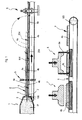
- Figure 1 shows schematically in two parts a vertical, longitudinal section through a portion of a system for forming flat ceramic products with colouring throughout substantially the whole of their bodies;
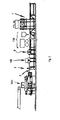
- Figure 2 illustrates schematically a side elevation of the system;
- Figure 3 illustrates very diagrammatically and in side elevation an overturning device for top unfinished products in the system; and
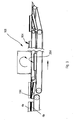
- Figure 4 is a diagrammatic perspective view of a squashing device of the system, but illustrating a modified version of a trimming device of the system.
- In Figure 1, 1 indicates an end portion of a batching/
mixing device 101 shown in Figure 2, which is provided with anextrusion die slot 2 and wherein a ceramic paste IP with at least two chromatic components is prepared. - The
extrusion die slot 2 is provided with atransverse blade 3 that cuts longitudinally, thereby minimising attrition phenomena, as extrusion progresses, the continuously extruded ceramic paste IP, on a horizontal plane, subdividing it into tworibbons cut faces - The continuous
multiple ribbon 4 at the outlet of theextrusion die slot 2 is collected and supported by amobile conveying surface 5, for example consisting of an endless conveyor belt on motor-driven andidle rollers 105, and conveyed to a transverse cutting station where cutting-to-size with asuitable means 6 occurs. - Subsequently, the conveying
surface 5 carries theunfinished products top product 4a in relation to thebottom product 4b occurs; theproduct 4a is thus placed next to thebottom product 4b with itscut face 104 upwards, as is thecut face 204 of thebottom product 4b. - Further along, the
products presser unit 7 whereat a squashing of theproducts - The compressing action causes the raw paste that makes up the
unfinished products - The flattening phase is followed by a phase of trimming of the
products cut lines 19 in Figure 4, with asuitable apparatus 8, to obtain the perimeter dimensions required of the products P which are sent for firing. - The
trimming device 8 shown in Figure 1 includes a vertically reciprocablerectangular cutting ring 8a. - In the version shown in Figure 4, the
device 8 includes a pair ofcutting wheels 8b mounted on ashaft 8c reciprocable by a piston-and-cylinder drive 8d. Thedevice 8 also includes another pair ofcutting wheels 8e mounted upon atransverse shaft 8f. - In a possible alternative embodiment, upstream of the flattening phase there may be an additional phase of spreading, on the
cut faces faces faces overall reference numeral 110. The length of the section ofmobile conveying surface 5 under theapparatus 110 may vary according to the number of chromatic applications that are to be performed and the type ofapparatus 110 to be used. - During the flattening phase, it is also possible to print high- or low-relief decorations on the
cut faces presser unit 7. - In a further possible embodiment, the flattening phase can be performed by using a
suitable roller device 9 shown in Figures 1 and 2 instead of thepresser unit 7 or in combination therewith.
Claims (30)
- A method of forming substantially flat ceramic products (P), comprising preparing a ceramic paste (IP), extruding the ceramic paste (IP) through an extrusion die (2) and over a cutter (3) to obtain a substantially continuous multiple ribbon (4) of paste with first and second ribbons (4a, 4b) of the multiple ribbon (4) not being joined together but having a separation plane that is substantially parallel to the faces of the multiple ribbon (4), and severing the first and second ribbons (4a, 4b) transversely to provide the products (P), characterised in that said extruding is performed substantially horizontally.
- A method according to claim 1, and further comprising, after said severing, squashing the products (P) to reduce their thicknesses and to increase their plan areas.
- A method according to claim 2, and further comprising, after said squashing, trimming the products (P) to size around their peripheries.
- A method according to claim 2 or 3, wherein, during said squashing, relief decoration is produced on the products (P).
- A method according to any preceding claim, wherein the multiple ribbon (4) has a width dimension which is substantially horizontal and a thickness dimension which is substantially vertical.
- A method according to claim 5, wherein said severing produces an upper row of products (P) and a lower row of products (P), and said method further comprises turning-over the products (P) of the upper row, so that those surfaces of the products (P) of the upper and lower rows initially adjacent the separation plane all face upwards.
- A method according to claim 6, wherein said turning-over causes the products (P) of the upper row to be placed side-by-side with the products (P) of the lower row.
- Method according to claim 6 or 7, and further comprising, after said turning-over, applying decorative material to said surfaces (104, 204).
- Apparatus for forming substantially flat ceramic products (P), comprising an extruder (1) having an extrusion die slot (2), a cutter (3) extending substantially parallelly to the die slot (2), and a severing device (6) to provide the products (P) downstream of the extruder (1), the arrangement being such that ceramic paste (IP) can be extruded from the die slot and cut by the cutter to obtain a substantially continuous multiple ribbon (4) of paste with first and second ribbons (4a, 4b) of the multiple ribbon (4) not being joined together but having a separation plane that is substantially parallel to the faces of the multiple ribbon (4), and the first and second ribbons (4a, 4b) can be severed transversely by the severing device (6) to provide the products (P), characterized in that the die slot (2) is directed substantially horizontally.
- Apparatus according to claim 9, and further comprising a squashing arrangement (7; 9) downstream of the severing device (6) for squashing the products (P).
- Apparatus according to claim 10, wherein the squashing arrangement (7; 9) comprises a pressing plate (7) reciprocable substantially perpendicularly to the products (P).
- Apparatus according to claim 10, or 11, wherein the squashing arrangement (7; 9) comprises at least one squashing roller (9).
- Apparatus according to any one of claims 10 to 12, wherein the squashing arrangement (7; 9) is provided with a squashing surface having relief ornamentation thereon for producing relief decoration on the products (P).
- Apparatus according to any one of claims 10 to 13, and further comprising a trimming device (8) downstream of the squashing arrangement (7; 9) for cutting the products (P) to size around their peripheries.
- Apparatus according to claim 14, wherein the trimming device (8) comprises a first pair of cutting elements (8b) reciprocable in a first direction and a second pair of cutting elements (8e) reciprocable in a second direction substantially perpendicular to the first direction.
- Apparatus according to any one of claims 9 to 15, wherein the die slot (2) has a width dimension which is substantially horizontal and a thickness dimension which is substantially vertical, the cutter (3) extends substantially horizontally, and the severing device (6) severs the first and second ribbons (4a,4b) into an upper row of products (P) and a lower row of products (P).
- Apparatus according to claim 16, and further comprising a turning-over device (108) for turning-over the upper row of products (P).
- Apparatus according to claim 17 as appended to claim 10, and further comprising a distribution device (110) between the turning-over device (108) and the squashing arrangement (7; 9) for distributing decorative material over the products (P).
- Apparatus according to any one of claims 8 to 18, and further comprising a horizontal conveyor (5) for receiving the multiple ribbon (4) as it leaves the die slot (2).
- Apparatus according to any one of claims 8 to 19, wherein the cutter (3) is provided with cutting surfaces having a low-friction coating thereon.
- A method of forming substantially flat ceramic products (P), comprising preparing a ceramic paste (IP), extruding the ceramic paste (IP) through an extrusion die (2) to obtain a substantially continuous ribbon (4), and severing the ribbon (4) to provide the products (P), characterised in that the individual products (P) so obtained are squashed to reduce their thicknesses and to increase their plan areas and are then cut to size around their peripheries.
- A method according to claim 21, wherein, as the products (P) are squashed, relief decoration is produced thereon.
- A method according to claim 21 or 22, and further comprising, before the squashing, applying decorative material to upwardly-facing surfaces (104, 204) of the products (P).
- Apparatus for forming substantially flat ceramic products (P), comprising an extruder (1) having an extrusion die slot (2), a severing device (6) to provide the products (P) downstream of the extruder (1), the arrangement being such that ceramic paste (IP) can be extruded from the die slot (2) to obtain a ribbon (4), and the ribbon (4) can be severed by the severing device (6) to provide the products (P), characterised in that the apparatus further comprises a squashing arrangement (7; 9) downstream of the severing device (6) for squashing the products (P) and a trimming device (8) downstream of the squashing arrangement (7; 9) for cutting the products (P) to size around their peripheries.
- Apparatus according to claim 24, wherein the squashing arrangement(7; 9) comprises a pressing plate (9) reciprocable substantially perpendicularly to the products (P).
- Apparatus according to claim 24 or 25, wherein the squashing arrangement (7; 9) comprises at least one squashing roller (9).
- Apparatus according to any one of claims 24 to 26, wherein the squashing arrangement (7; 9) is provided with a squashing surface having relief ornamentation thereon for producing relief decoration on the products (P).
- Apparatus according to any one of claims 24 to 27, and further comprising a trimming device (8) downstream of the squashing arrangement (7;9) for cutting the products (P) to size around their peripheries.
- Apparatus according to claim 28, wherein the trimming device (8) comprises a first pair of cutting elements (8b) reciprocable in a first direction and a second pair of cutting elements (8e) reciprocable in a second direction substantially perpendicular to the first direction.
- Apparatus according to any one of claims 24 to 29, and further comprising a distribution device (110) upstream of the squashing device (7; 9) for distributing decorative material over the products (P).
Priority Applications (1)
| Application Number | Priority Date | Filing Date | Title |
|---|---|---|---|
| EP10160133A EP2210724A1 (en) | 2003-02-14 | 2004-01-26 | Method and apparatus for forming flat ceramic products |
Applications Claiming Priority (2)
| Application Number | Priority Date | Filing Date | Title |
|---|---|---|---|
| ITMO20030031 | 2003-02-14 | ||
| IT000031A ITMO20030031A1 (en) | 2003-02-14 | 2003-02-14 | EXTRUSIVE PROCEDURE FOR THE FORMING OF MANUFACTURES |
Related Child Applications (1)
| Application Number | Title | Priority Date | Filing Date |
|---|---|---|---|
| EP10160133.4 Division-Into | 2010-04-16 |
Publications (3)
| Publication Number | Publication Date |
|---|---|
| EP1447191A2 true EP1447191A2 (en) | 2004-08-18 |
| EP1447191A3 EP1447191A3 (en) | 2006-03-22 |
| EP1447191B1 EP1447191B1 (en) | 2011-03-16 |
Family
ID=27677336
Family Applications (2)
| Application Number | Title | Priority Date | Filing Date |
|---|---|---|---|
| EP04001546A Expired - Lifetime EP1447191B1 (en) | 2003-02-14 | 2004-01-26 | Method and apparatus for forming flat ceramic products |
| EP10160133A Ceased EP2210724A1 (en) | 2003-02-14 | 2004-01-26 | Method and apparatus for forming flat ceramic products |
Family Applications After (1)
| Application Number | Title | Priority Date | Filing Date |
|---|---|---|---|
| EP10160133A Ceased EP2210724A1 (en) | 2003-02-14 | 2004-01-26 | Method and apparatus for forming flat ceramic products |
Country Status (2)
| Country | Link |
|---|---|
| EP (2) | EP1447191B1 (en) |
| IT (1) | ITMO20030031A1 (en) |
Cited By (5)
| Publication number | Priority date | Publication date | Assignee | Title |
|---|---|---|---|---|
| EP1798014A3 (en) * | 2005-12-19 | 2011-01-19 | Gruppo Barbieri & Tarozzi S.p.A. | Cutting device for an extruder |
| CN101037004B (en) * | 2007-02-14 | 2011-04-06 | 徐平 | Mould for forming ceramic tile and the method for forming the ceramic tile by using the mould |
| CN102581927A (en) * | 2011-01-10 | 2012-07-18 | 云浮威洋石材有限公司 | Process for processing artificial quartz stone |
| CN102581942A (en) * | 2012-03-07 | 2012-07-18 | 深圳顺络电子股份有限公司 | Trimming method for ceramic slab of surface mount device and apparatus thereof |
| EP3670124A1 (en) | 2018-12-18 | 2020-06-24 | Steenfabriek Maasmechelen bvba | Brick slip |
Families Citing this family (3)
| Publication number | Priority date | Publication date | Assignee | Title |
|---|---|---|---|---|
| CN102248584B (en) * | 2011-07-28 | 2013-04-10 | 成都芙蓉新型建材有限公司 | Wallboard flattening machine |
| CN111469260B (en) * | 2020-04-28 | 2022-04-12 | 王安全 | A kind of gypsum block prepared by dry production |
| CN111958793B (en) * | 2020-07-22 | 2021-12-03 | 台州丽盾智能科技有限公司 | Vase trades a mouthful equipment for ceramic manufacture |
Citations (1)
| Publication number | Priority date | Publication date | Assignee | Title |
|---|---|---|---|---|
| US4292359A (en) | 1979-01-24 | 1981-09-29 | Laria-Laterizi Rivestimenti Ed Affini-S.P.A. | Process for the continuous production of a partly finished clay product |
Family Cites Families (14)
| Publication number | Priority date | Publication date | Assignee | Title |
|---|---|---|---|---|
| US1943506A (en) * | 1931-10-16 | 1934-01-16 | Edward S Baer | Brick machine |
| US2113717A (en) * | 1935-05-29 | 1938-04-12 | Brown Davis | Method and machine for making clay shingles |
| GB880892A (en) * | 1959-10-05 | 1961-10-25 | Alexander John Cherney | An improved method and apparatus for the manufacture of tiles |
| FR1253656A (en) * | 1960-04-08 | 1961-02-10 | Process for manufacturing ceramic tiles and equipment for its implementation | |
| GB930708A (en) * | 1960-04-16 | 1963-07-10 | Fetok Gmbh | Improvements relating to facing tiles |
| FR1425619A (en) * | 1965-01-27 | 1966-01-24 | Improvements in manufacturing processes for flat elements based on clay or mineral compounds, for tiles, wall coverings and other uses | |
| NL7514346A (en) * | 1975-06-11 | 1976-12-14 | Lingl Hans | METHOD AND DEVICE FOR IMPRESSING DECORS ON THE SURFACE OF PLATES MADE BY CUTTING CLAY FROM STRONG CLAY. |
| DE3113661A1 (en) * | 1981-04-04 | 1982-10-28 | Gesellschaft für Keramikmaschinen mbH & Co KG, 3418 Uslar | Process and device for producing ceramic tiles |
| DK230984D0 (en) * | 1984-05-09 | 1984-05-09 | Eternit Fab Dansk As | METHOD AND APPARATUS FOR EXTRADING A PUT-BODY |
| JPH03219918A (en) * | 1990-01-26 | 1991-09-27 | Mitsubishi Materials Corp | Method for patterning extrusion-molded body |
| JP2540439B2 (en) * | 1993-09-22 | 1996-10-02 | 義和 中村 | Relief porcelain board manufacturing method and manufacturing apparatus |
| FR2714048B1 (en) * | 1993-12-16 | 1996-02-16 | Everite Sa | Article, in particular a building cladding plate, and method of manufacturing such an article. |
| JP4356211B2 (en) * | 2000-08-08 | 2009-11-04 | 株式会社Inax | Tile forming method |
| DE10112439A1 (en) * | 2001-03-15 | 2002-09-19 | Oleg L Kulikov | Device for producing ceramic masses by extrusion has insert protruding beyond nozzle end in flow direction, insulated surface processing tool at distance from nozzle end |
-
2003
- 2003-02-14 IT IT000031A patent/ITMO20030031A1/en unknown
-
2004
- 2004-01-26 EP EP04001546A patent/EP1447191B1/en not_active Expired - Lifetime
- 2004-01-26 EP EP10160133A patent/EP2210724A1/en not_active Ceased
Patent Citations (1)
| Publication number | Priority date | Publication date | Assignee | Title |
|---|---|---|---|---|
| US4292359A (en) | 1979-01-24 | 1981-09-29 | Laria-Laterizi Rivestimenti Ed Affini-S.P.A. | Process for the continuous production of a partly finished clay product |
Cited By (7)
| Publication number | Priority date | Publication date | Assignee | Title |
|---|---|---|---|---|
| EP1798014A3 (en) * | 2005-12-19 | 2011-01-19 | Gruppo Barbieri & Tarozzi S.p.A. | Cutting device for an extruder |
| CN101037004B (en) * | 2007-02-14 | 2011-04-06 | 徐平 | Mould for forming ceramic tile and the method for forming the ceramic tile by using the mould |
| CN102581927A (en) * | 2011-01-10 | 2012-07-18 | 云浮威洋石材有限公司 | Process for processing artificial quartz stone |
| CN102581942A (en) * | 2012-03-07 | 2012-07-18 | 深圳顺络电子股份有限公司 | Trimming method for ceramic slab of surface mount device and apparatus thereof |
| CN102581942B (en) * | 2012-03-07 | 2015-05-20 | 深圳顺络电子股份有限公司 | Trimming method for ceramic slab of surface mount device and apparatus thereof |
| EP3670124A1 (en) | 2018-12-18 | 2020-06-24 | Steenfabriek Maasmechelen bvba | Brick slip |
| BE1026888B1 (en) * | 2018-12-18 | 2020-07-22 | Steenfabriek Maasmechelen Bvba | Hand-molded brick strip |
Also Published As
| Publication number | Publication date |
|---|---|
| EP1447191A3 (en) | 2006-03-22 |
| ITMO20030031A0 (en) | 2003-02-14 |
| EP1447191B1 (en) | 2011-03-16 |
| ITMO20030031A1 (en) | 2004-08-15 |
| EP2210724A1 (en) | 2010-07-28 |
Similar Documents
| Publication | Publication Date | Title |
|---|---|---|
| CN1230082C (en) | Method and apparatus for joining and supplying separated dough blocks | |
| CA1218902A (en) | High production method and apparatus for forming filled edible products | |
| US4689236A (en) | Method for forming edible products having an inner portion enveloped by a dissimilar outer portion | |
| US4741916A (en) | Method of and apparatus for producing individual dough pieces of substantially constant size and shape | |
| US5017320A (en) | Process for the manufacuture of stratified pieces such as roof tiles and wall tiles | |
| US4647468A (en) | Apparatus for forming filled edible products without waste | |
| EP0164234B1 (en) | Method and apparatus for producing laminated products | |
| RU2007106224A (en) | METHODS AND DEVICES FOR OBTAINING ALTERNATIVELY PROFILED CONFECTIONERY GOODS | |
| EP1447191B1 (en) | Method and apparatus for forming flat ceramic products | |
| US7316556B2 (en) | Apparatus for cutting dough with nested pattern cutters | |
| EP1594666B1 (en) | Method and plant for forming ceramic tiles or slabs | |
| US4719117A (en) | High production method for forming filled edible products | |
| US4292359A (en) | Process for the continuous production of a partly finished clay product | |
| JPH0698614B2 (en) | Method for continuously producing shaped body of fiber-reinforced hydraulic mass | |
| DE19838075C1 (en) | Method for production of angled bricks for wall cladding | |
| EP1710062B1 (en) | Method for forming multi-coloured porcellainized ceramic stone tiles by extrusion | |
| GB2028710A (en) | A method and apparatus for the manufacture of ceramic bricks | |
| JP3056686B2 (en) | Notched kneaded product and method for producing the same | |
| KR20010042644A (en) | Method and device for making crab leg meat like product made with boiled fish paste | |
| JP3167698B2 (en) | Cutting device for kneaded products | |
| US5772939A (en) | Manufacture of building products | |
| RU2311032C2 (en) | Process line for bread pieces | |
| CN102463622A (en) | Method and apparatus for forming flat ceramic products | |
| JPH01291759A (en) | Production of uncooked noodle and apparatus therefor | |
| GB2440647A (en) | Plant for producing wafer fingers |
Legal Events
| Date | Code | Title | Description |
|---|---|---|---|
| PUAI | Public reference made under article 153(3) epc to a published international application that has entered the european phase |
Free format text: ORIGINAL CODE: 0009012 |
|
| AK | Designated contracting states |
Kind code of ref document: A2 Designated state(s): AT BE BG CH CY CZ DE DK EE ES FI FR GB GR HU IE IT LI LU MC NL PT RO SE SI SK TR |
|
| AX | Request for extension of the european patent |
Extension state: AL LT LV MK |
|
| RIN1 | Information on inventor provided before grant (corrected) |
Inventor name: CORONI, STEFANO |
|
| RIC1 | Information provided on ipc code assigned before grant |
Ipc: 7B 28B 11/10 B Ipc: 7B 28B 11/12 B Ipc: 7B 28B 11/16 B Ipc: 7B 28B 13/04 B Ipc: 7B 28B 3/20 A |
|
| PUAL | Search report despatched |
Free format text: ORIGINAL CODE: 0009013 |
|
| AK | Designated contracting states |
Kind code of ref document: A3 Designated state(s): AT BE BG CH CY CZ DE DK EE ES FI FR GB GR HU IE IT LI LU MC NL PT RO SE SI SK TR |
|
| AX | Request for extension of the european patent |
Extension state: AL LT LV MK |
|
| 17P | Request for examination filed |
Effective date: 20060914 |
|
| AKX | Designation fees paid |
Designated state(s): ES IT |
|
| RAP1 | Party data changed (applicant data changed or rights of an application transferred) |
Owner name: GRUPPO BARBIERI & TAROZZI S.R.L. |
|
| REG | Reference to a national code |
Ref country code: DE Ref legal event code: 8566 |
|
| 17Q | First examination report despatched |
Effective date: 20071005 |
|
| GRAP | Despatch of communication of intention to grant a patent |
Free format text: ORIGINAL CODE: EPIDOSNIGR1 |
|
| RAP1 | Party data changed (applicant data changed or rights of an application transferred) |
Owner name: SITI - B&T GROUP S.P.A. |
|
| GRAS | Grant fee paid |
Free format text: ORIGINAL CODE: EPIDOSNIGR3 |
|
| RIN1 | Information on inventor provided before grant (corrected) |
Inventor name: CARONI, STEFANO |
|
| RIN1 | Information on inventor provided before grant (corrected) |
Inventor name: CARONI, STEFANO |
|
| GRAA | (expected) grant |
Free format text: ORIGINAL CODE: 0009210 |
|
| AK | Designated contracting states |
Kind code of ref document: B1 Designated state(s): ES IT |
|
| PG25 | Lapsed in a contracting state [announced via postgrant information from national office to epo] |
Ref country code: ES Free format text: LAPSE BECAUSE OF FAILURE TO SUBMIT A TRANSLATION OF THE DESCRIPTION OR TO PAY THE FEE WITHIN THE PRESCRIBED TIME-LIMIT Effective date: 20110627 |
|
| PLBE | No opposition filed within time limit |
Free format text: ORIGINAL CODE: 0009261 |
|
| STAA | Information on the status of an ep patent application or granted ep patent |
Free format text: STATUS: NO OPPOSITION FILED WITHIN TIME LIMIT |
|
| 26N | No opposition filed |
Effective date: 20111219 |
|
| PG25 | Lapsed in a contracting state [announced via postgrant information from national office to epo] |
Ref country code: IT Free format text: LAPSE BECAUSE OF FAILURE TO SUBMIT A TRANSLATION OF THE DESCRIPTION OR TO PAY THE FEE WITHIN THE PRESCRIBED TIME-LIMIT Effective date: 20110316 |