EP1447183B1 - Roboter, deren Leitung durch einen axial nachgiebigen Balg geführt ist - Google Patents
Roboter, deren Leitung durch einen axial nachgiebigen Balg geführt ist Download PDFInfo
- Publication number
- EP1447183B1 EP1447183B1 EP04002449.9A EP04002449A EP1447183B1 EP 1447183 B1 EP1447183 B1 EP 1447183B1 EP 04002449 A EP04002449 A EP 04002449A EP 1447183 B1 EP1447183 B1 EP 1447183B1
- Authority
- EP
- European Patent Office
- Prior art keywords
- bellows
- robot hand
- line
- hand wrist
- robot
- Prior art date
- Legal status (The legal status is an assumption and is not a legal conclusion. Google has not performed a legal analysis and makes no representation as to the accuracy of the status listed.)
- Expired - Lifetime
Links
- 230000007704 transition Effects 0.000 claims description 8
- 238000010422 painting Methods 0.000 claims description 6
- 238000007789 sealing Methods 0.000 claims description 5
- 230000002093 peripheral effect Effects 0.000 claims description 4
- 210000002445 nipple Anatomy 0.000 claims description 3
- 244000043261 Hevea brasiliensis Species 0.000 claims description 2
- 229920001971 elastomer Polymers 0.000 claims description 2
- 229920003052 natural elastomer Polymers 0.000 claims description 2
- 229920001194 natural rubber Polymers 0.000 claims description 2
- 229920001084 poly(chloroprene) Polymers 0.000 claims description 2
- 239000005060 rubber Substances 0.000 claims description 2
- 210000000707 wrist Anatomy 0.000 claims 16
- YCKRFDGAMUMZLT-UHFFFAOYSA-N Fluorine atom Chemical compound [F] YCKRFDGAMUMZLT-UHFFFAOYSA-N 0.000 claims 1
- 229920000459 Nitrile rubber Polymers 0.000 claims 1
- 239000005062 Polybutadiene Substances 0.000 claims 1
- NIXOWILDQLNWCW-UHFFFAOYSA-N acrylic acid group Chemical group C(C=C)(=O)O NIXOWILDQLNWCW-UHFFFAOYSA-N 0.000 claims 1
- 238000006073 displacement reaction Methods 0.000 claims 1
- 229910052731 fluorine Inorganic materials 0.000 claims 1
- 239000011737 fluorine Substances 0.000 claims 1
- 229920002857 polybutadiene Polymers 0.000 claims 1
- 238000004804 winding Methods 0.000 claims 1
- 239000000463 material Substances 0.000 description 5
- 239000012530 fluid Substances 0.000 description 3
- 239000007788 liquid Substances 0.000 description 3
- 230000004323 axial length Effects 0.000 description 2
- 238000004140 cleaning Methods 0.000 description 2
- 238000004519 manufacturing process Methods 0.000 description 2
- 239000002184 metal Substances 0.000 description 2
- NLHHRLWOUZZQLW-UHFFFAOYSA-N Acrylonitrile Chemical compound C=CC#N NLHHRLWOUZZQLW-UHFFFAOYSA-N 0.000 description 1
- 230000008901 benefit Effects 0.000 description 1
- 239000011248 coating agent Substances 0.000 description 1
- 238000000576 coating method Methods 0.000 description 1
- 238000011161 development Methods 0.000 description 1
- 230000018109 developmental process Effects 0.000 description 1
- 230000004069 differentiation Effects 0.000 description 1
- 229920001973 fluoroelastomer Polymers 0.000 description 1
- 230000004048 modification Effects 0.000 description 1
- 238000012986 modification Methods 0.000 description 1
- 239000003973 paint Substances 0.000 description 1
- 239000004033 plastic Substances 0.000 description 1
- 229920003023 plastic Polymers 0.000 description 1
- 230000008439 repair process Effects 0.000 description 1
- 238000007493 shaping process Methods 0.000 description 1
- 229920003048 styrene butadiene rubber Polymers 0.000 description 1
- 239000000725 suspension Substances 0.000 description 1
Images



Classifications
-
- H—ELECTRICITY
- H02—GENERATION; CONVERSION OR DISTRIBUTION OF ELECTRIC POWER
- H02G—INSTALLATION OF ELECTRIC CABLES OR LINES, OR OF COMBINED OPTICAL AND ELECTRIC CABLES OR LINES
- H02G9/00—Installations of electric cables or lines in or on the ground or water
- H02G9/06—Installations of electric cables or lines in or on the ground or water in underground tubes or conduits; Tubes or conduits therefor
-
- B—PERFORMING OPERATIONS; TRANSPORTING
- B25—HAND TOOLS; PORTABLE POWER-DRIVEN TOOLS; MANIPULATORS
- B25J—MANIPULATORS; CHAMBERS PROVIDED WITH MANIPULATION DEVICES
- B25J19/00—Accessories fitted to manipulators, e.g. for monitoring, for viewing; Safety devices combined with or specially adapted for use in connection with manipulators
- B25J19/0025—Means for supplying energy to the end effector
- B25J19/0029—Means for supplying energy to the end effector arranged within the different robot elements
-
- B—PERFORMING OPERATIONS; TRANSPORTING
- B25—HAND TOOLS; PORTABLE POWER-DRIVEN TOOLS; MANIPULATORS
- B25J—MANIPULATORS; CHAMBERS PROVIDED WITH MANIPULATION DEVICES
- B25J19/00—Accessories fitted to manipulators, e.g. for monitoring, for viewing; Safety devices combined with or specially adapted for use in connection with manipulators
- B25J19/0075—Means for protecting the manipulator from its environment or vice versa
- B25J19/0083—Means for protecting the manipulator from its environment or vice versa using gaiters
-
- Y—GENERAL TAGGING OF NEW TECHNOLOGICAL DEVELOPMENTS; GENERAL TAGGING OF CROSS-SECTIONAL TECHNOLOGIES SPANNING OVER SEVERAL SECTIONS OF THE IPC; TECHNICAL SUBJECTS COVERED BY FORMER USPC CROSS-REFERENCE ART COLLECTIONS [XRACs] AND DIGESTS
- Y10—TECHNICAL SUBJECTS COVERED BY FORMER USPC
- Y10T—TECHNICAL SUBJECTS COVERED BY FORMER US CLASSIFICATION
- Y10T74/00—Machine element or mechanism
- Y10T74/20—Control lever and linkage systems
- Y10T74/20207—Multiple controlling elements for single controlled element
- Y10T74/20305—Robotic arm
- Y10T74/20329—Joint between elements
- Y10T74/20335—Wrist
Definitions
- the invention relates to a robot hand axis, in particular for a painting robot, according to the preamble of claim 1.
- a disadvantage of these known hand axles is the fact that the lines can be damaged in operation, because they are exposed in the internal passage of the hand axis strong friction on the inner walls and the transition radii. Such line damage leads to costly production losses in industrial robots in production. In addition, when a line damage always a complete line package must be replaced, resulting in significant repair costs.
- the invention is therefore an object of the invention to provide a robot hand shaft with a cable feedthrough, which prevents damage to the lines during operation and liquid exchange between the hand axis and the robot arm is omitted, the lines must have sufficient axial clearance to one Follow the movement of the hand axis accordingly.
- the object is, starting from the well-known hand axle described above according to the preamble of claim 1, achieved by the characterizing features of claim 1.
- the invention provides for suspending the line located in the line bushing by means of an axially compliant bellows arranged within the line bushing, which on the one hand enables axial play of the line and on the other forms a guide for the line.
- the leads in the leadthrough of the hand axis are at least partially helically or meanderingly arranged to allow additional axial play of the lead upon movement of the hand axis.
- the bellows is arranged at at least one end of the cable feedthrough and leads the lines there axially yielding.
- a bellows is arranged in the line bushing at the transition points to an adjacent member of the robot in order to guide the lines there axially yielding.
- the bellows preferably does not extend over the entire length of the cable feedthrough, but essentially serves only for axially compliant suspension of the lines in the cable feedthrough.
- the bellows preferably allows an axial relative movements between the line bushing and the lines guided therein, wherein the line bushing itself can also be designed as bellows.
- the cable bushing consists only of a tube.
- the bellows preferably also seals off the line guide in order to prevent a liquid exchange between the hand axis and the robot arm, for example in the case of a painting robot.
- the line feedthrough preferably passes through the robot arm and the hand axis, wherein the line feedthrough is sealed at the transition between the robot arm and the hand axis by the bellows.
- the bellows in this case therefore has two technical functions, namely on the one hand, the axially compliant guidance of the line in the line bushing and on the other hand, the sealing of the cable feedthrough.
- the invention is not limited to the bellows sealing the conduit passage at the transition between the robotic arm and the hand axis. Rather, it is also possible within the scope of the invention for the bellows to seal the conduit feedthrough at other transitions between two adjacent members of the robot.
- bellows used in the context of the invention is to be understood generally and is not restricted to the bellows which are preferably used.
- bellows also includes those resilient elements which guide the line in an axially yielding manner.
- Suitable materials for the bellows are preferably natural rubber, styrene-butadiene rubber, acrylonitrile rubber, Chlorobutadiene rubber, fluoro rubber or polychlorotetrafluoroethylene. These materials have proven to be advantageous in terms of durability, resilience and density behavior.
- the invention is not limited to the materials listed above for producing the bellows. Rather, the bellows can also consist of other compliant materials, with a variety of plastics can be used.
- the bellows can also be made of metal, wherein the axial compliance of the bellows is achieved by folding in the bellows, which is why the bellows is referred to in this embodiment of the invention as a metal bellows.
- the line feedthrough receives a plurality of lines, wherein the lines are guided through a respective bellows.
- the individual bellows can therefore have different properties, such as a different flexibility, elasticity and / or maximum deflection in the axial direction.
- the sealing capacity of the individual bellows may be different, since, for example, electrical cables can be laid in a separate cable bushing, so that the associated bellows need not necessarily be sealed.
- the bellows for paint lines should be sealed in order to avoid a fluid exchange between the hand axis and the robot arm.
- the invention is not limited to such embodiments in which the bellows for the individual lines have different properties. It exists in the context of Invention also the possibility that the bellows are identical for the individual lines.
- the lines are led together by a single bellows.
- the lines are preferably passed through a guide plate which fixes the lines relative to each other in a predetermined position.
- the guide plate with the individual lines is then guided as a whole by the bellows axially yielding.
- the bellows therefore preferably surrounds the guide plate and is preferably pressed by an annular spring against the peripheral edge of the guide plate.
- the bellows is preferably attached to a mounting plate, which preferably has a bore for the passage of the conduit.
- the bellows For attachment of the bellows to the mounting plate of the bellows may have a mounting flange, wherein the connection between the mounting flange of the bellows and the mounting plate can be done for example by a screw.
- This type of attachment is particularly suitable for a leadership of multiple lines through a bellows.
- the attachment of the bellows can also be done with the help of a Einschraubnippels which is screwed into a bore of the mounting plate and to which the bellows is pressed.
- This type of attachment is particularly suitable when each line is passed through a separate bellows.
- the axial compliance of the bellows is preferably in the range of 5 mm to 30 mm, wherein any intermediate values are possible. In principle, however, there is also the possibility that the bellows has a smaller or greater axial compliance.
- the line is preferably wound around a guide element, which is preferably arranged centrally.
- This guide element may be, for example, a line that is easily axially stretchable.
- the line bushing is then a line package with axially expandable lines in the middle, which are wrapped spirally by other lines.
- a line used in the context of the invention is likewise to be understood generally and includes, for example, hoses, tubes, light guides and electrical lines.
- FIG. 1 shows a robot arm 1 of an otherwise conventionally constructed painting robot for painting motor vehicle parts.
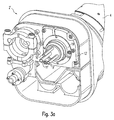
- the robot arm 1 has a connection piece 2 for connecting a robot hand axis 3, wherein various embodiments of the connection piece 2 according to the invention are arranged in the FIGS. 2a and 2 B or 3a and 3b are shown in detail.
- the robot hand axis 3 has three relatively rotatable members 4, 5, 6, wherein the member 4 is guided by the connector 2 and is rotatable relative thereto.
- the robot hand axis 3 has a line leadthrough 8, through which lines 9, 10, 11 can be guided from the robot arm 1 through the robot hand axis 3 to the rotary atomizer.
- the lines 9, 10, 11 are in the FIGS. 2a and 2 B These are hoses for supplying the rotary atomizer with coating material, drive air and shaping air.
- the lines, 9, 10, 11 are stretched or compressed in the axial direction due to the rotations of the individual members 4, 5, 6 of the robot hand axis 3 and moreover subjected to a torsional load. To enable an axial Length compensation depending on the robot position, the lines 9, 10, 11 therefore guided in the connector 2 axially yielding.
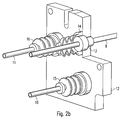
- a mounting plate 12 is screwed into the connecting piece 2, which has three holes for the passage of the lines 9, 10, 11.
- a screw-in nipple 13 is screwed, in which the lines 9, 10, 11 are guided axially displaceable.
- a bellows 14, 15, 16 pressed onto the Einschraubnippel 13 respectively.
- the bellows 14, 15, 16 lead the lines 9, 10, 11, so axially resilient and seal beyond the cable bushings, whereby a fluid exchange between the robot hand axis 3 and the robot arm 1 is prevented. This is advantageous because a liquid exchange between the hand axis 3 and the robot arm 1 would require costly cleaning.
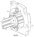
- FIGS. 3a and 3b illustrated embodiment is largely consistent with that described above and in the FIGS. 2a and 2 B illustrated embodiment, so that the same reference numerals are used for matching components, which are marked for differentiation only by an apostrophe. Furthermore, only the special features of this embodiment will be described below, while otherwise to the above description of the FIGS. 2a and 2 B referenced to avoid unnecessary repetition.
- a peculiarity of this embodiment is that the line 9 ', 10', 11 'are guided together through a single bore 17 in the mounting plate 12' and are guided by a single bellows 18 axially resilient.
- the bellows 18 To attach the bellows 18 to the mounting plate 12 ', the bellows 18 an annular mounting flange 19 which is screwed to the mounting plate 12'.
- the individual lines 9 ', 10', 11 ' are guided through holes in a guide plate 20, wherein the guide plate 20 is circular disk-shaped and the lines 9', 10 ', 11' fixed in a predetermined position relative to each other.
- the mouth of the bellows 18 encloses the guide plate 20 at its peripheral edge, wherein a tension spring 21 presses the bellows on the peripheral edge of the guide plate 20.
- FIG. 4 a further embodiment of a robot hand axis 3 'according to the invention with three relatively rotatable members 4', 5 ', 6' and a line bushing 8 ', wherein in the line bushing 8' numerous lines 22 are spirally guided around centered further lines 23.
- the helical guide of the lines 23 in this case allows an axial length compensation in a movement of the individual members 4 ', 5', 6 'of the robot hand axis 3'.
Landscapes
- Engineering & Computer Science (AREA)
- Robotics (AREA)
- Mechanical Engineering (AREA)
- Manipulator (AREA)
Description
- Die Erfindung betrifft eine Roboterhandachse, insbesondere für einen Lackierroboter, gemäß dem Oberbegriff des Anspruchs 1.
- Aus
US 4 708 580 sind Industrieroboter mit einer Handachse bekannt, die drei Freiheitsgrade aufweist, wobei die Handachse eine Innendurchführung für Signal- und Versorgungsleitungen aufweist. Bei einer Bewegung der Handachse in den einzelnen Freiheitsgraden werden die Leitungen in der Innendurchführung der Handachse in axialer Richtung gedehnt bzw. gestaucht und darüber hinaus einer Torsionsbelastung unterworfen. Dies wird bei den bekannten Industrierobotern mit einer derartigen Handachse dadurch berücksichtigt, dass die Leitungen in der Innendurchführung locker verlegt werden und deshalb ein ausreichendes axiales Spiel aufweisen. - Nachteilig an diesen bekannten Handachsen ist die Tatsache, dass die Leitungen im Betrieb beschädigt werden können, weil sie in der Innendurchführung der Handachse starken Reibungen an den Innenwandungen und den Übergangsradien ausgesetzt sind. Derartige Leitungsbeschädigungen führen bei Industrierobotern in der Produktion zu kostenträchtigen Produktionsausfällen. Darüber hinaus muss bei einer Leitungsbeschädigung immer ein vollständiges Leitungspaket ausgewechselt werden, was zu erheblichen Reparaturkosten führt.
- Aus
JP H11 277478 A - Ein weiterer Nachteil der bekannten Handachsen besteht darin, dass die Leitungen in der Innendurchführung der Handachse ohne eine geeignete Abdichtung geführt werden, um überhaupt eine Bewegung der Handachse zu ermöglichen. Aufgrund der unzureichenden Abdichtung der Leitungen kann es deshalb zu einem Flüssigkeitsaustausch zwischen der Handachse und dem Roboterarm kommen, was eine kostenintensive Reinigung erfordert.
- Aus
US 4 632 632 A undDE 196 16 765 A sind linear bewegliche Anordnungen bekannt, wobei es sich jedoch nicht um eine Roboterhandachse mit drehbaren Gliedern handelt. Schließlich ist ausEP 1 036 711 A eine Wanddurchführung bekannt, die als solche ebenfalls fernliegend ist. - Der Erfindung liegt deshalb die Aufgabe zugrunde, eine Roboterhandachse mit einer Leitungsdurchführung zu schaffen, bei der eine Beschädigung der Leitungen während des Betriebs verhindert wird und ein Flüssigkeitsaustausch zwischen der Handachse und dem Roboterarm unterbleibt, wobei die Leitungen ein ausreichendes axiales Spiel aufweisen müssen, um einer Bewegung der Handachse entsprechend folgen zu können.
- Die Aufgabe wird, ausgehend von der eingangs beschriebenen bekannten Handachse gemäß dem Oberbegriff des Anspruchs 1, durch die kennzeichnenden Merkmale des Anspruchs 1 gelöst.
- Die Erfindung sieht vor, die in der Leitungsdurchführung befindliche Leitung mittels eines innerhalb der Leitungsdurchführung angeordneten axial nachgiebigen Balgs aufzuhängen, der zum einen ein axiales Spiel der Leitung ermöglicht und zum anderen eine Führung für die Leitung bildet.
- In einem bevorzugten Ausführungsbeispiel sind zusätzlich die Leitungen in der Leitungsdurchführung der Handachse mindestens teilweise spiralförmig oder mäanderförmig angeordnet, um ein zusätzliches axiales Spiel der Leitung bei einer Bewegung der Handachse zu ermöglichen.
- In einem bevorzugten Ausführungsbeispiel der Erfindung ist der Balg an mindestens einem Ende der Leitungsdurchführung angeordnet und führt die Leitungen dort axial nachgiebig. Es ist jedoch auch möglich, dass in der Leitungsdurchführung jeweils an den Übergangsstellen zu einem benachbarten Glied des Roboters ein Balg angeordnet ist, um die Leitungen dort axial nachgiebig zu führen. Der Balg erstreckt sich bei dem erfindungsgemäßen Roboter also vorzugsweise nicht über die gesamte Länge der Leitungsdurchführung, sondern dient im wesentlichen nur zur axial nachgiebigen Aufhängung der Leitungen in der Leitungsdurchführung. Hierbei ermöglicht der Balg vorzugsweise eine axiale Relativbewegungen zwischen der Leitungsdurchführung und den darin geführten Leitungen, wobei die Leitungsdurchführung selbst ebenfalls als Balg ausgeführt sein kann. Es besteht jedoch alternativ auch die Möglichkeit, dass die Leitungsdurchführung lediglich aus einem Rohr besteht.
- Vorzugsweise dichtet der Balg die Leitungsführung darüber hinaus auch ab, um beispielsweise bei einem Lackierroboter einen Flüssigkeitsaustausch zwischen der Handachse und dem Roboterarm zu verhindern. Hierbei geht die Leitungsdurchführung vorzugsweise durch den Roboterarm und die Handachse hindurch, wobei die Leitungsdurchführung an dem Übergang zwischen dem Roboterarm und der Handachse durch den Balg abgedichtet ist. Der Balg hat hierbei also zwei technische Funktionen, nämlich zum einen die axial nachgiebige Führung der Leitung in der Leitungsdurchführung und zum anderen die Abdichtung der Leitungsdurchführung.
- Die Erfindung ist jedoch nicht darauf beschränkt, dass der Balg die Leitungsdurchführung an dem Übergang zwischen dem Roboterarm und der Handachse abdichtet. Es ist im Rahmen der Erfindung vielmehr auch möglich, dass der Balg die Leitungsdurchführung an anderen Übergängen zwischen zwei benachbarten Gliedern des Roboters abdichtet.
- Der im Rahmen der Erfindung verwendete Begriff eines Balgs ist allgemein zu verstehen und nicht auf die vorzugsweise eingesetzten Faltenbälge beschränkt. Der Begriff eines Balgs umfasst beispielsweise auch solche nachgiebigen Elemente, welche die Leitung axial nachgiebig führen.
- Als Material für den Balg eignen sich vorzugsweise Natur-Kautschuk, Styrol-Butadien-Kautschuk, Acryl-Nitril-Kautschuk, Chlorbutadien-Kautschuk, Fluor-Kautschuk oder Polychlortetrafluorethylen. Diese Werkstoffe haben sich hinsichtlich Haltbarkeit, Nachgiebigkeit und Dichteverhalten als vorteilhaft erwiesen. Die Erfindung ist jedoch nicht auf die vorstehend aufgeführten Materialien zur Herstellung des Balgs beschränkt. Vielmehr kann der Balg auch aus anderen nachgiebigen Materialien bestehen, wobei vielfältige Kunststoffe zum Einsatz kommen können.
- Darüber hinaus kann der Balg auch aus Metall bestehen, wobei die axiale Nachgiebigkeit des Balgs durch Falten in dem Balg erreicht wird, weshalb der Balg in dieser Ausführungsform der Erfindung auch als Metallfaltenbalg bezeichnet wird.
- In einer bevorzugten Ausführungsform der Erfindung nimmt die Leitungsdurchführung mehrere Leitungen auf, wobei die Leitungen durch jeweils einen Balg geführt werden.
- Dies bietet den Vorteil, dass die axiale Nachgiebigkeit der einzelnen Bälge individuell auf die jeweilige Leitung abgestimmt werden kann. Die einzelnen Bälge können hierbei also unterschiedliche Eigenschaften aufweisen, wie beispielsweise eine unterschiedliche Nachgiebigkeit, Elastizität und/oder Maximalauslenkung in axialer Richtung.
- Darüber hinaus kann auch das Dichtungsvermögen der einzelnen Bälge unterschiedlich sein, da beispielsweise Elektroleitungen in einer separaten Leitungsdurchführung verlegt sein können, so dass die zugehörigen Bälge nicht unbedingt abgedichtet sein müssen. Die Bälge für Lackleitungen sollten dagegen abgedichtet sein, um einen Flüssigkeitsaustausch zwischen der Handachse und dem Roboterarm zu vermeiden.
- Die Erfindung ist jedoch nicht auf solche Ausführungsformen beschränkt, bei denen die Bälge für die einzelnen Leitungen unterschiedliche Eigenschaften aufweisen. Es besteht im Rahmen der Erfindung auch die Möglichkeit, dass die Bälge für die einzelnen Leitungen baugleich sind.
- Darüber hinaus ist es alternativ auch möglich, dass mehrere Leitungen gemeinsam durch einen einzigen Balg geführt werden. In diesem Fall sind die Leitungen vorzugsweise durch eine Führungsplatte hindurch geführt, welche die Leitungen relativ zueinander in einer vorgegebenen Position fixiert. Die Führungsplatte mit den einzelnen Leitungen wird dann als Ganzes von dem Balg axial nachgiebig geführt. Der Balg umschließt deshalb vorzugsweise die Führungsplatte und wird vorzugsweise durch eine Ringfeder gegen den Umfangsrand der Führungsplatte gedrückt.
- Der Balg ist vorzugsweise an einer Montageplatte befestigt, die vorzugsweise eine Bohrung zur Durchführung der Leitung aufweist.
- Zur Befestigung des Balgs an der Montageplatte kann der Balg einen Befestigungsflansch aufweisen, wobei die Verbindung zwischen dem Befestigungsflansch des Balgs und der Montageplatte beispielsweise durch eine Verschraubung erfolgen kann. Diese Art der Befestigung eignet sich insbesondere bei einer Führung mehrerer Leitungen durch einen Balg.
- Die Befestigung des Balgs kann jedoch auch mit Hilfe eines Einschraubnippels erfolgen, der in eine Bohrung der Montageplatte eingeschraubt wird und auf den der Balg aufgepresst wird. Diese Art der Befestigung eignet sich insbesondere dann, wenn jede Leitung durch einen separaten Balg geführt wird.
- Die axiale Nachgiebigkeit des Balgs liegt vorzugsweise im Bereich von 5 mm bis 30 mm, wobei beliebige Zwischenwerte möglich sind. Grundsätzlich besteht jedoch auch die Möglichkeit, dass der Balg eine kleinere oder größere axiale Nachgiebigkeit aufweist.
- Bei der eingangs erwähnten Ausführungsform der Erfindung mit einer spiralförmigen Führung der Leitung in der Leitungsdurchführung wird die Leitung vorzugsweise um ein Führungselement gewickelt, das vorzugsweise mittig angeordnet ist. Bei diesem Führungselement kann es sich beispielsweise um eine Leitung handeln, die problemlos axial dehnbar ist. In der Leitungsdurchführung befindet sich dann ein Leitungspaket mit axial dehnbaren Leitungen in der Mitte, die von weiteren Leitungen spiralförmig umwickelt sind.
- Weiterhin ist zu erwähnen, dass der im Rahmen der Erfindung verwendete Begriff einer Leitung ebenfalls allgemein zu verstehen ist und beispielsweise Schläuche, Rohre, Lichtleiter sowie elektrische Leitungen umfasst.
- Andere vorteilhafte Weiterbildungen der Erfindung sind in den Unteransprüchen gekennzeichnet oder werden nachstehend zusammen mit der Beschreibung der bevorzugten Ausführungsbeispiele der Erfindung anhand der Figuren näher erläutert.
- Es zeigen:
- Figur 1
- eine perspektivische Ansicht eines Roboterarms mit einer Handachse mit drei Freiheitsgraden,
- Figur 2a
- eine Perspektivansicht eines Anschlussstücks des Roboterarms am Übergang der Handachse,
- Figur 2b
- eine teilaufgeschnittene Detailansicht von
Figur 2a , - Figur 3a
- eine Perspektivansicht eines alternativen Anschlussstücks des Roboterarms am Übergang zu der Handachse,
- Figur 3b
- eine teilaufgeschnittene Detailansicht aus
Figur 3a sowie - Figur 4
- eine teilweise aufgeschnittene Ansicht der in
Figur 1 dargestellten Handachse bei einem Ausführungsbeispiel der Erfindung. - Die perspektivische Ansicht in
Figur 1 zeigt einen Roboterarm 1 eines ansonsten in herkömmlicher Weise aufgebauten Lackierroboters zur Lackierung von Kraftfahrzeugteilen. - An seinem distalen Ende weist der Roboterarm 1 ein Anschlussstück 2 zum Anschluss einer Roboterhandachse 3 auf, wobei verschiedene erfindungsgemäße Ausgestaltungen des Anschlussstücks 2 in den
Figuren 2a und2b beziehungsweise 3a und 3b detailliert dargestellt sind. - Die Roboterhandachse 3 weist drei relativ zueinander verdrehbaren Glieder 4, 5, 6 auf, wobei das Glied 4 von dem Anschlussstück 2 geführt wird und relativ dazu verdrehbar ist.
- Das Glied 6 weist dagegen eine Stirnfläche 7 zur Befestigung eines herkömmlichen Rotationszerstäubers auf.
- Weiterhin ist zu erwähnen, dass die Roboterhandachse 3 eine Leitungsdurchführung 8 aufweist, durch die Leitungen 9, 10, 11 von dem Roboterarm 1 durch die Roboterhandachse 3 hindurch zu dem Rotationszerstäuber geführt werden können.
- Die Leitungen 9, 10, 11 sind in den
Figuren 2a und2b dargestellt, wobei es sich um Schläuche zur Versorgung des Rotationszerstäubers mit Beschichtungsmaterial, Antriebsluft und Lenkluft handelt. - Im Betrieb werden die Leitungen, 9, 10, 11 aufgrund der Drehungen der einzelnen Glieder 4, 5, 6 der Roboterhandachse 3 in axialer Richtung gedehnt bzw. gestaucht und darüber hinaus eine Torsionsbelastung unterworfen. Zur Ermöglichung eines axialen Längenausgleichs in Abhängigkeit von der Roboterstellung sind die Leitungen 9, 10, 11 deshalb in dem Anschlussstück 2 axial nachgiebig geführt.
- Hierzu ist in das Anschlussstück 2 eine Montageplatte 12 eingeschraubt, die drei Bohrungen zur Durchführung der Leitungen 9, 10, 11 aufweist. In diese Bohrungen ist jeweils ein Einschraubnippel 13 eingeschraubt, in dem die Leitungen 9, 10, 11 axial verschiebbar geführt werden.
- Auf der dem Roboterarm 1 zugewandten Seite der Montageplatte 12 ist jeweils ein Faltenbalg 14, 15, 16 auf den Einschraubnippel 13 aufgepreßt. Die Faltenbälge 14, 15, 16 führen die Leitungen 9, 10, 11, also axial nachgiebig und dichten darüber hinaus die Leitungsdurchführungen ab, wodurch ein Flüssigkeitsaustausch zwischen der Roboterhandachse 3 und dem Roboterarm 1 verhindert wird. Dies ist vorteilhaft, weil ein Flüssigkeitsaustausch zwischen der Handachse 3 und dem Roboterarm 1 eine kostenintensive Reinigung erforderlich machen würde.
- Das in den
Figuren 3a und3b dargestellte Ausführungsbeispiel stimmt weitgehend mit dem vorstehend beschriebenen und in denFiguren 2a und2b dargestellten Ausführungsbeispiel überein, so dass für übereinstimmende Bauelemente dieselben Bezugszeichen verwendet werden, die zur Unterscheidung lediglich durch ein Apostroph gekennzeichnet sind. Weiterhin werden im Folgenden lediglich die Besonderheiten dieses Ausführungsbeispiels beschrieben, während ansonsten auf die vorstehende Beschreibung zu denFiguren 2a und2b verwiesen wird, um unnötige Wiederholungen zu vermeiden. - Eine Besonderheit dieses Ausführungsbeispiels besteht darin, dass die Leitung 9', 10', 11' gemeinsam durch eine einzige Bohrung 17 in der Montageplatte 12' hindurch geführt werden und von einem einzigen Faltenbalg 18 axial nachgiebig geführt werden.
- Zur Befestigung des Faltenbalgs 18 an der Montageplatte 12' weist der Faltenbalg 18 einen ringförmigen Befestigungsflansch 19 auf, der an der Montageplatte 12' festgeschraubt ist.
- Die einzelnen Leitungen 9', 10', 11' sind durch Bohrungen in einer Führungsplatte 20 hindurch geführt, wobei die Führungsplatte 20 kreisscheibenförmig ist und die Leitungen 9', 10', 11' in einer vorgegebenen Position relativ zueinander fixiert. Die Mündungsöffnung des Faltenbalgs 18 umschließt die Führungsplatte 20 an deren Umfangsrand, wobei eine Spannfeder 21 den Faltenbalg auf den Umfangsrand der Führungsplatte 20 presst.
- Schließlich zeigt
Figur 4 ein weiteres Ausführungsbeispiel einer erfindungsgemäßen Roboterhandachse 3' mit drei relativ zueinander verdrehbaren Gliedern 4', 5', 6' und einer Leitungsdurchführung 8', wobei in der Leitungsdurchführung 8' zahlreiche Leitungen 22 spiralförmig um mittig angeordnete weitere Leitungen 23 geführt sind. Die spiralförmige Führung der Leitungen 23 ermöglicht hierbei einen axialen Längenausgleich bei einer Bewegung der einzelnen Glieder 4', 5', 6' der Roboterhandachse 3'. - Die Erfindung ist nicht auf die vorstehend beschriebenen Ausführungsbeispiele der Erfindung beschränkt. Vielmehr ist eine Vielzahl von Varianten und Abwandlungen möglich, die ebenfalls von dem Erfindungsgedanken Gebrauch machen und deshalb in den durch die Ansprüche definierten Schutzbereich fallen.
Claims (16)
- Roboterhandachse für einen Roboter, insbesondere für einen Lackierroboter, mita) mehreren beweglichen Glieder (4-6, 4'-6'), die zueinander drehbar sind,b) einer Leitungsdurchführung (8, 8'), undc) mindestens einer Leitung (9-11, 9'-11', 22, 23), die von der Leitungsdurchführung (8, 8') aufgenommen wird,dadurch gekennzeichnet,d) dass die Leitung (9-11, 9'-11', 22, 23) mittels eines innerhalb der Leitungsdurchführung (8, 8') angeordneten axial nachgiebigen Balgs (14-16, 18) aufgehängt ist, so dass bei einer Änderung der Roboterstellung eine Axialbewegung der Leitung (9-11, 9'-11', 22, 23) ermöglicht wird.
- Roboterhandachse gemäß Anspruch 1, dadurch gekennzeichnet, dass die Leitung (9-11, 9'-11', 22, 23) in der Leitungsdurchführung (8, 8') mindestens teilweise spiralförmig oder mäanderförmig angeordnet ist, so dass bei einer Änderung der Roboterstellung eine Axialbewegung der Leitung (9-11, 9'-11', 22, 23) ermöglicht wird.
- Roboterhandachse nach Anspruch 1 oder 2, dadurch gekennzeichnet, dass der Balg (14-16, 18) die Leitungsdurchführung (8) abdichtet.
- Roboterhandachse nach einem der vorhergehenden Ansprüche, dadurch gekennzeichnet, dass der Balg (14-16, 18) an mindestens einem Ende der Leitungsdurchführung (8) und/oder an einem Übergang zu einem anderen Glied (4-6, 4'-6') des Roboters angeordnet ist.
- Roboterhandachse nach mindestens einem der vorhergehenden Ansprüche, dadurch gekennzeichnet, dass mehrere Leitungen (9-11) vorgesehen sind, wobei die Leitungen (9-11) jeweils einzeln durch jeweils einen Balg (14-16) geführt werden.
- Roboterhandachse nach Anspruch 5, dadurch gekennzeichnet, dass die Bälge (14-16) für die einzelnen Leitungen (9-11) unterschiedliche Eigenschaften aufweisen.
- Roboterhandachse nach Anspruch 6, dadurch gekennzeichnet, dass die Bälge (14-16) für die einzelnen Leitungen (9-11) eine unterschiedliche Nachgiebigkeit, Elastizität und/oder Maximalauslenkung in axialer Richtung und/oder ein unterschiedliches Dichtungsvermögen aufweisen.
- Roboterhandachse nach mindestens einem der vorhergehenden Ansprüche, dadurch gekennzeichnet, dass mehrere Leitungen (14'-16') vorgesehen sind, wobei die Leitungen (14'-16') gemeinsam durch einen Balg (18) geführt werden.
- Roboterhandachse nach Anspruch 8, dadurch gekennzeichnet, dass die Leitungen (14'-16') durch eine Führungsplatte (20) hindurchgeführt sind, die von dem Balg (18) axial nachgiebig geführt wird.
- Roboterhandachse nach Anspuch 9, dadurch gekennzeichnet, dass der Balg (18) die Führungsplatte (20) umschließt und durch eine Spannfeder (21) gegen den Umfangsrand der Führungsplatte (20) gedrückt wird.
- Roboterhandachse nach mindestens einem der vorhergehenden Ansprüche, dadurch gekennzeichnet, dass der Balg (18) einen Befestigungsflansch (19) aufweist, der an einer Montageplatte (12') befestigt ist.
- Roboterhandachse nach mindestens einem der vorhergehenden Ansprüche, dadurch gekennzeichnet, dass der Balg (14-16) auf einen Einschraubnippel (13) aufgepresst ist, wobei der Einschraubnippel (13) in eine Bohrung in der Montageplatte eingeschraubt ist.
- Roboterhandachse nach mindestens einem der vorhergehenden Ansprüche, dadurch gekennzeichnet, dass der Balg (14-16, 18) mindestens teilweise aus Natur-Kautschuk, Styrol-Butadien-Kautschuk, Acryl-Nitril-Kautschuk, Chlorbutadien-Kautschuk, Fluor-Kautschuk oder Polychlortetrafluorethylen besteht.
- Roboterhandachse nach mindestens einem der vorhergehenden Ansprüche, dadurch gekennzeichnet, dass der Balg (14-16, 18) eine axiale Nachgiebigkeit aufweist, die im Bereich von 5 mm bis 30 mm liegt.
- Roboterhandachse nach Anspruch 1, dadurch gekennzeichnet, dass die Leitung (22) spiralförmig um ein in der Leitungsdurchführung (8') angeordnetes Führungselement gewickelt ist.
- Roboterhandachse nach Anspruch 15, dadurch gekennzeichnet, dass das Führungselement eine axial dehnbare Leitung (23) ist.
Applications Claiming Priority (2)
| Application Number | Priority Date | Filing Date | Title |
|---|---|---|---|
| DE10304652 | 2003-02-05 | ||
| DE10304652A DE10304652A1 (de) | 2003-02-05 | 2003-02-05 | Roboter |
Publications (2)
| Publication Number | Publication Date |
|---|---|
| EP1447183A1 EP1447183A1 (de) | 2004-08-18 |
| EP1447183B1 true EP1447183B1 (de) | 2016-11-30 |
Family
ID=32667994
Family Applications (1)
| Application Number | Title | Priority Date | Filing Date |
|---|---|---|---|
| EP04002449.9A Expired - Lifetime EP1447183B1 (de) | 2003-02-05 | 2004-02-04 | Roboter, deren Leitung durch einen axial nachgiebigen Balg geführt ist |
Country Status (5)
| Country | Link |
|---|---|
| US (1) | US7677130B2 (de) |
| EP (1) | EP1447183B1 (de) |
| CA (1) | CA2456891C (de) |
| DE (1) | DE10304652A1 (de) |
| MX (1) | MXPA04001163A (de) |
Families Citing this family (16)
| Publication number | Priority date | Publication date | Assignee | Title |
|---|---|---|---|---|
| DE102004014209A1 (de) * | 2004-03-23 | 2005-10-13 | Dürr Systems GmbH | Roboter |
| DE102004052558A1 (de) * | 2004-10-29 | 2006-05-04 | Saurer Gmbh & Co. Kg | Zahnradpumpe |
| JP4349320B2 (ja) * | 2005-05-12 | 2009-10-21 | パナソニック株式会社 | マニピュレータ型ロボット |
| US7870807B2 (en) * | 2005-09-26 | 2011-01-18 | Durr Systems Inc. | Multi axis robot wrist and method of operation |
| EP1772194B1 (de) | 2005-10-07 | 2019-01-09 | Dürr Systems AG | Beschichtungsmittel-Versorgungseinrichtung und zugehöriges Betriebsverfahren |
| WO2009015850A2 (de) * | 2007-08-02 | 2009-02-05 | Kuka Systems Gmbh | Drehanschlusskupplung |
| DE102007051018A1 (de) | 2007-10-25 | 2009-04-30 | Daimler Ag | Fertigungseinrichtung |
| DE102009010953A1 (de) * | 2009-02-27 | 2010-09-02 | Dürr Systems GmbH | Roboter, insbesondere Lackierroboter |
| FR2977508B1 (fr) * | 2011-07-06 | 2013-08-16 | Sames Technologies | Station de nettoyage-remplissage pour moyens de projection |
| US8524312B2 (en) * | 2011-11-16 | 2013-09-03 | Csl Silicones Inc. | Applicator for spraying elastomeric materials |
| JP5539454B2 (ja) * | 2012-07-20 | 2014-07-02 | ファナック株式会社 | 中空部材を備えた産業用ロボットの線条体処理構造 |
| CN105881589B (zh) * | 2016-06-24 | 2018-10-30 | 博众精工科技股份有限公司 | 一种机械手圆盘护罩装置 |
| CN107160433B (zh) * | 2017-06-05 | 2023-09-12 | 上海发那科机器人有限公司 | 一种管线保护装置 |
| JP7388887B2 (ja) * | 2019-11-13 | 2023-11-29 | ファナック株式会社 | ロボットの線条体ユニットおよび線条体配線方法 |
| JP7524662B2 (ja) * | 2020-08-04 | 2024-07-30 | セイコーエプソン株式会社 | ロボット |
| CN114474079B (zh) * | 2022-04-15 | 2022-06-28 | 深圳市纬华机械有限公司 | 一种兼容多种型号工件的机械手及控制方法 |
Citations (2)
| Publication number | Priority date | Publication date | Assignee | Title |
|---|---|---|---|---|
| JPS62188384U (de) * | 1986-05-20 | 1987-11-30 | ||
| JPH11277478A (ja) * | 1998-03-26 | 1999-10-12 | Tokico Ltd | 工業用ロボット |
Family Cites Families (15)
| Publication number | Priority date | Publication date | Assignee | Title |
|---|---|---|---|---|
| US4378959A (en) * | 1979-06-13 | 1983-04-05 | Thermwood Corporation | Apparatus for performing work functions |
| US4632632A (en) * | 1983-08-30 | 1986-12-30 | Automation Equipment Company | Programmable industrial robot having simplified construction |
| US4688983A (en) * | 1984-05-21 | 1987-08-25 | Unimation Inc. | Low cost robot |
| US4708580A (en) | 1985-01-22 | 1987-11-24 | Gmf Robotics Corporation | Mechanical wrist mechanism |
| ATE80082T1 (de) * | 1987-07-10 | 1992-09-15 | Gregory C Hirschmann | Lineareinheit fuer eine montage-einrichtung der handhabungstechnik. |
| US4839490A (en) * | 1987-10-09 | 1989-06-13 | General Electric Company | Gas shielded metal arc welding torch for limited access welding |
| CA2017674C (en) * | 1990-05-30 | 1995-06-13 | Henning Hansen | Articulated support arm for welding equipment |
| DE9103497U1 (de) * | 1991-03-21 | 1991-06-20 | Kuka Schweissanlagen + Roboter Gmbh, 8900 Augsburg | Mehrachsiger Manipulator |
| JP2746543B2 (ja) * | 1995-02-21 | 1998-05-06 | 株式会社神戸製鋼所 | 産業用ロボットの手首装置 |
| DE19616765A1 (de) * | 1996-04-26 | 1997-11-06 | Eistert Theodor | Linearführungsarm |
| US5848556A (en) * | 1997-02-26 | 1998-12-15 | Samsung Electronics Co., Ltd. | Robot having dust minimizing cable arrangement |
| DE19911649A1 (de) | 1999-03-16 | 2000-09-21 | Volkswagen Ag | Wanddurchführung für strangförmige Körper |
| SE516877C2 (sv) * | 1999-12-01 | 2002-03-19 | Abb Ab | Ett förfarande och ett vridorgan för dragning av ett kablage för en industrirobot |
| DE20005551U1 (de) * | 2000-03-24 | 2000-07-20 | Kuka Roboter GmbH, 86165 Augsburg | Hochflexibles Schlauchendstück |
| JP2003305684A (ja) * | 2002-04-15 | 2003-10-28 | Fanuc Ltd | 相対回転機構における線条体敷設構造 |
-
2003
- 2003-02-05 DE DE10304652A patent/DE10304652A1/de not_active Ceased
-
2004
- 2004-01-30 US US10/768,373 patent/US7677130B2/en active Active
- 2004-02-04 EP EP04002449.9A patent/EP1447183B1/de not_active Expired - Lifetime
- 2004-02-04 CA CA2456891A patent/CA2456891C/en not_active Expired - Lifetime
- 2004-02-04 MX MXPA04001163A patent/MXPA04001163A/es active IP Right Grant
Patent Citations (2)
| Publication number | Priority date | Publication date | Assignee | Title |
|---|---|---|---|---|
| JPS62188384U (de) * | 1986-05-20 | 1987-11-30 | ||
| JPH11277478A (ja) * | 1998-03-26 | 1999-10-12 | Tokico Ltd | 工業用ロボット |
Also Published As
| Publication number | Publication date |
|---|---|
| DE10304652A1 (de) | 2004-08-19 |
| CA2456891A1 (en) | 2004-08-05 |
| EP1447183A1 (de) | 2004-08-18 |
| US20040237154A1 (en) | 2004-11-25 |
| MXPA04001163A (es) | 2005-09-21 |
| CA2456891C (en) | 2012-03-27 |
| US7677130B2 (en) | 2010-03-16 |
Similar Documents
| Publication | Publication Date | Title |
|---|---|---|
| EP2461948B1 (de) | Parallelroboter | |
| EP0552429B1 (de) | Endoskop mit einem steuerbaren distalen Endstück | |
| EP1447183A1 (de) | Roboter, deren Leitung durch einen axial nachgiebigen Balg geführt ist | |
| EP0260219B1 (de) | Roboterarm | |
| DE202006020825U1 (de) | Vorrichtung zum Führen eines zumindest eine Versorgungsleitung aufweisenden Schlauches | |
| DE3431033A1 (de) | Roboterhandgelenk | |
| DE102011000097B4 (de) | Arm-Kopplungsvorrichtung für Roboter | |
| DE102013011681A1 (de) | Nabelgliedanordnung eines Industrieroboters mit hohlem Glied | |
| DE102013004824A1 (de) | Versorgungselement-Führungsmechanismus am Vorderende eines Handgelenks eines Industrieroboters | |
| EP0017779A1 (de) | Druckmittelbetätigte Lineareinheit für Handhabungsgeräte der industriellen Fertigung | |
| EP1502659A1 (de) | Farbwechselventilanordnung einer Beschichtungsanlage | |
| DE3418372A1 (de) | Antrieb fuer eine allgemeine bahnbewegung und in diese integrierte antriebsvorrichtung | |
| EP0439242B1 (de) | Lineareinheit | |
| DE69917604T2 (de) | Multifunktionsbündel und damit ausgerüsteter industrieroboter | |
| DE19519939C1 (de) | Schwenkvorrichtung für Handhabungseinrichtungen | |
| DE102016114562B3 (de) | Drehbetätigter Pumpenkopf für ein englisches Ventil | |
| DE102013220148B3 (de) | Ausgleichseinheit und Ausgleichssystem | |
| DE69816151T2 (de) | Seilverbinder für eine Fernbedienungsanordnung | |
| DE102006028145A1 (de) | Roboter | |
| EP1602458B1 (de) | Roboterhandachse mit einer Schlauchführung für einen Lackierroboter | |
| DE102020104557A1 (de) | Kabelfixierungsstruktur | |
| DE3036939A1 (de) | Zahnaerztliche handstueckanordnung | |
| EP1059459A1 (de) | Fluidbetätigter Drehantrieb | |
| DE102004014209A1 (de) | Roboter | |
| DE202017004834U1 (de) | T-förmige Robotergelenkeinheit mit mindestens zwei oder mehr Andockstellen zur flexiblen Gestaltung und Umrüstung von Roboterarmen |
Legal Events
| Date | Code | Title | Description |
|---|---|---|---|
| PUAI | Public reference made under article 153(3) epc to a published international application that has entered the european phase |
Free format text: ORIGINAL CODE: 0009012 |
|
| AK | Designated contracting states |
Kind code of ref document: A1 Designated state(s): AT BE BG CH CY CZ DE DK EE ES FI FR GB GR HU IE IT LI LU MC NL PT RO SE SI SK TR |
|
| AX | Request for extension of the european patent |
Extension state: AL LT LV MK |
|
| 17P | Request for examination filed |
Effective date: 20041223 |
|
| AKX | Designation fees paid |
Designated state(s): AT BE BG CH CY CZ DE DK EE ES FI FR GB GR HU IE IT LI LU MC NL PT RO SE SI SK TR |
|
| 17Q | First examination report despatched |
Effective date: 20091028 |
|
| RAP1 | Party data changed (applicant data changed or rights of an application transferred) |
Owner name: DUERR SYSTEMS GMBH |
|
| GRAP | Despatch of communication of intention to grant a patent |
Free format text: ORIGINAL CODE: EPIDOSNIGR1 |
|
| RIC1 | Information provided on ipc code assigned before grant |
Ipc: H02G 9/06 20060101ALI20160812BHEP Ipc: B25J 19/00 20060101AFI20160812BHEP |
|
| RAP1 | Party data changed (applicant data changed or rights of an application transferred) |
Owner name: DUERR SYSTEMS AG |
|
| INTG | Intention to grant announced |
Effective date: 20160919 |
|
| GRAS | Grant fee paid |
Free format text: ORIGINAL CODE: EPIDOSNIGR3 |
|
| GRAA | (expected) grant |
Free format text: ORIGINAL CODE: 0009210 |
|
| AK | Designated contracting states |
Kind code of ref document: B1 Designated state(s): AT BE BG CH CY CZ DE DK EE ES FI FR GB GR HU IE IT LI LU MC NL PT RO SE SI SK TR |
|
| REG | Reference to a national code |
Ref country code: CH Ref legal event code: EP Ref country code: GB Ref legal event code: FG4D Free format text: NOT ENGLISH |
|
| REG | Reference to a national code |
Ref country code: AT Ref legal event code: REF Ref document number: 849353 Country of ref document: AT Kind code of ref document: T Effective date: 20161215 |
|
| REG | Reference to a national code |
Ref country code: IE Ref legal event code: FG4D Free format text: LANGUAGE OF EP DOCUMENT: GERMAN |
|
| REG | Reference to a national code |
Ref country code: DE Ref legal event code: R096 Ref document number: 502004015396 Country of ref document: DE |
|
| REG | Reference to a national code |
Ref country code: NL Ref legal event code: MP Effective date: 20161130 |
|
| PG25 | Lapsed in a contracting state [announced via postgrant information from national office to epo] |
Ref country code: GR Free format text: LAPSE BECAUSE OF FAILURE TO SUBMIT A TRANSLATION OF THE DESCRIPTION OR TO PAY THE FEE WITHIN THE PRESCRIBED TIME-LIMIT Effective date: 20170301 Ref country code: SE Free format text: LAPSE BECAUSE OF FAILURE TO SUBMIT A TRANSLATION OF THE DESCRIPTION OR TO PAY THE FEE WITHIN THE PRESCRIBED TIME-LIMIT Effective date: 20161130 |
|
| PG25 | Lapsed in a contracting state [announced via postgrant information from national office to epo] |
Ref country code: FI Free format text: LAPSE BECAUSE OF FAILURE TO SUBMIT A TRANSLATION OF THE DESCRIPTION OR TO PAY THE FEE WITHIN THE PRESCRIBED TIME-LIMIT Effective date: 20161130 Ref country code: PT Free format text: LAPSE BECAUSE OF FAILURE TO SUBMIT A TRANSLATION OF THE DESCRIPTION OR TO PAY THE FEE WITHIN THE PRESCRIBED TIME-LIMIT Effective date: 20170330 Ref country code: BE Free format text: LAPSE BECAUSE OF NON-PAYMENT OF DUE FEES Effective date: 20170228 Ref country code: ES Free format text: LAPSE BECAUSE OF FAILURE TO SUBMIT A TRANSLATION OF THE DESCRIPTION OR TO PAY THE FEE WITHIN THE PRESCRIBED TIME-LIMIT Effective date: 20161130 |
|
| PG25 | Lapsed in a contracting state [announced via postgrant information from national office to epo] |
Ref country code: NL Free format text: LAPSE BECAUSE OF FAILURE TO SUBMIT A TRANSLATION OF THE DESCRIPTION OR TO PAY THE FEE WITHIN THE PRESCRIBED TIME-LIMIT Effective date: 20161130 |
|
| PG25 | Lapsed in a contracting state [announced via postgrant information from national office to epo] |
Ref country code: DK Free format text: LAPSE BECAUSE OF FAILURE TO SUBMIT A TRANSLATION OF THE DESCRIPTION OR TO PAY THE FEE WITHIN THE PRESCRIBED TIME-LIMIT Effective date: 20161130 Ref country code: EE Free format text: LAPSE BECAUSE OF FAILURE TO SUBMIT A TRANSLATION OF THE DESCRIPTION OR TO PAY THE FEE WITHIN THE PRESCRIBED TIME-LIMIT Effective date: 20161130 Ref country code: RO Free format text: LAPSE BECAUSE OF FAILURE TO SUBMIT A TRANSLATION OF THE DESCRIPTION OR TO PAY THE FEE WITHIN THE PRESCRIBED TIME-LIMIT Effective date: 20161130 Ref country code: CZ Free format text: LAPSE BECAUSE OF FAILURE TO SUBMIT A TRANSLATION OF THE DESCRIPTION OR TO PAY THE FEE WITHIN THE PRESCRIBED TIME-LIMIT Effective date: 20161130 Ref country code: SK Free format text: LAPSE BECAUSE OF FAILURE TO SUBMIT A TRANSLATION OF THE DESCRIPTION OR TO PAY THE FEE WITHIN THE PRESCRIBED TIME-LIMIT Effective date: 20161130 |
|
| PG25 | Lapsed in a contracting state [announced via postgrant information from national office to epo] |
Ref country code: BG Free format text: LAPSE BECAUSE OF FAILURE TO SUBMIT A TRANSLATION OF THE DESCRIPTION OR TO PAY THE FEE WITHIN THE PRESCRIBED TIME-LIMIT Effective date: 20170228 Ref country code: IT Free format text: LAPSE BECAUSE OF FAILURE TO SUBMIT A TRANSLATION OF THE DESCRIPTION OR TO PAY THE FEE WITHIN THE PRESCRIBED TIME-LIMIT Effective date: 20161130 |
|
| REG | Reference to a national code |
Ref country code: DE Ref legal event code: R097 Ref document number: 502004015396 Country of ref document: DE |
|
| PG25 | Lapsed in a contracting state [announced via postgrant information from national office to epo] |
Ref country code: MC Free format text: LAPSE BECAUSE OF FAILURE TO SUBMIT A TRANSLATION OF THE DESCRIPTION OR TO PAY THE FEE WITHIN THE PRESCRIBED TIME-LIMIT Effective date: 20161130 |
|
| REG | Reference to a national code |
Ref country code: CH Ref legal event code: PL |
|
| PLBE | No opposition filed within time limit |
Free format text: ORIGINAL CODE: 0009261 |
|
| STAA | Information on the status of an ep patent application or granted ep patent |
Free format text: STATUS: NO OPPOSITION FILED WITHIN TIME LIMIT |
|
| GBPC | Gb: european patent ceased through non-payment of renewal fee |
Effective date: 20170228 |
|
| PG25 | Lapsed in a contracting state [announced via postgrant information from national office to epo] |
Ref country code: CH Free format text: LAPSE BECAUSE OF NON-PAYMENT OF DUE FEES Effective date: 20170228 Ref country code: LI Free format text: LAPSE BECAUSE OF NON-PAYMENT OF DUE FEES Effective date: 20170228 |
|
| 26N | No opposition filed |
Effective date: 20170831 |
|
| REG | Reference to a national code |
Ref country code: IE Ref legal event code: MM4A |
|
| PG25 | Lapsed in a contracting state [announced via postgrant information from national office to epo] |
Ref country code: SI Free format text: LAPSE BECAUSE OF FAILURE TO SUBMIT A TRANSLATION OF THE DESCRIPTION OR TO PAY THE FEE WITHIN THE PRESCRIBED TIME-LIMIT Effective date: 20161130 |
|
| REG | Reference to a national code |
Ref country code: FR Ref legal event code: ST Effective date: 20171031 |
|
| PG25 | Lapsed in a contracting state [announced via postgrant information from national office to epo] |
Ref country code: LU Free format text: LAPSE BECAUSE OF NON-PAYMENT OF DUE FEES Effective date: 20170204 |
|
| PG25 | Lapsed in a contracting state [announced via postgrant information from national office to epo] |
Ref country code: FR Free format text: LAPSE BECAUSE OF NON-PAYMENT OF DUE FEES Effective date: 20170228 |
|
| REG | Reference to a national code |
Ref country code: BE Ref legal event code: MM Effective date: 20170228 |
|
| PG25 | Lapsed in a contracting state [announced via postgrant information from national office to epo] |
Ref country code: GB Free format text: LAPSE BECAUSE OF NON-PAYMENT OF DUE FEES Effective date: 20170228 Ref country code: IE Free format text: LAPSE BECAUSE OF NON-PAYMENT OF DUE FEES Effective date: 20170204 |
|
| REG | Reference to a national code |
Ref country code: AT Ref legal event code: MM01 Ref document number: 849353 Country of ref document: AT Kind code of ref document: T Effective date: 20170204 |
|
| PG25 | Lapsed in a contracting state [announced via postgrant information from national office to epo] |
Ref country code: AT Free format text: LAPSE BECAUSE OF NON-PAYMENT OF DUE FEES Effective date: 20170204 |
|
| PG25 | Lapsed in a contracting state [announced via postgrant information from national office to epo] |
Ref country code: HU Free format text: LAPSE BECAUSE OF FAILURE TO SUBMIT A TRANSLATION OF THE DESCRIPTION OR TO PAY THE FEE WITHIN THE PRESCRIBED TIME-LIMIT; INVALID AB INITIO Effective date: 20040204 |
|
| PG25 | Lapsed in a contracting state [announced via postgrant information from national office to epo] |
Ref country code: CY Free format text: LAPSE BECAUSE OF NON-PAYMENT OF DUE FEES Effective date: 20161130 |
|
| PG25 | Lapsed in a contracting state [announced via postgrant information from national office to epo] |
Ref country code: TR Free format text: LAPSE BECAUSE OF FAILURE TO SUBMIT A TRANSLATION OF THE DESCRIPTION OR TO PAY THE FEE WITHIN THE PRESCRIBED TIME-LIMIT Effective date: 20161130 |
|
| PGFP | Annual fee paid to national office [announced via postgrant information from national office to epo] |
Ref country code: DE Payment date: 20230216 Year of fee payment: 20 |
|
| P01 | Opt-out of the competence of the unified patent court (upc) registered |
Effective date: 20230512 |
|
| REG | Reference to a national code |
Ref country code: DE Ref legal event code: R071 Ref document number: 502004015396 Country of ref document: DE |