EP1447161A1 - Sprühdüse - Google Patents
Sprühdüse Download PDFInfo
- Publication number
- EP1447161A1 EP1447161A1 EP03405086A EP03405086A EP1447161A1 EP 1447161 A1 EP1447161 A1 EP 1447161A1 EP 03405086 A EP03405086 A EP 03405086A EP 03405086 A EP03405086 A EP 03405086A EP 1447161 A1 EP1447161 A1 EP 1447161A1
- Authority
- EP
- European Patent Office
- Prior art keywords
- nozzle
- spray
- wall
- mold
- release agent
- Prior art date
- Legal status (The legal status is an assumption and is not a legal conclusion. Google has not performed a legal analysis and makes no representation as to the accuracy of the status listed.)
- Granted
Links
- 239000007921 spray Substances 0.000 title claims abstract description 85
- 239000003795 chemical substances by application Substances 0.000 claims abstract description 14
- 238000004512 die casting Methods 0.000 claims abstract description 12
- 239000000203 mixture Substances 0.000 claims description 5
- 239000000243 solution Substances 0.000 claims description 4
- 238000005507 spraying Methods 0.000 claims description 3
- 239000000126 substance Substances 0.000 claims description 3
- 239000000839 emulsion Substances 0.000 claims description 2
- 239000000725 suspension Substances 0.000 claims description 2
- XLYOFNOQVPJJNP-UHFFFAOYSA-N water Substances O XLYOFNOQVPJJNP-UHFFFAOYSA-N 0.000 claims description 2
- 238000005266 casting Methods 0.000 description 7
- 238000000889 atomisation Methods 0.000 description 2
- 239000007864 aqueous solution Substances 0.000 description 1
- 230000015572 biosynthetic process Effects 0.000 description 1
- 238000001816 cooling Methods 0.000 description 1
- 238000005516 engineering process Methods 0.000 description 1
- 239000007788 liquid Substances 0.000 description 1
- 229910001338 liquidmetal Inorganic materials 0.000 description 1
- 239000000314 lubricant Substances 0.000 description 1
- 239000002184 metal Substances 0.000 description 1
- 238000000034 method Methods 0.000 description 1
- 238000007493 shaping process Methods 0.000 description 1
Images

Classifications
-
- B—PERFORMING OPERATIONS; TRANSPORTING
- B05—SPRAYING OR ATOMISING IN GENERAL; APPLYING FLUENT MATERIALS TO SURFACES, IN GENERAL
- B05B—SPRAYING APPARATUS; ATOMISING APPARATUS; NOZZLES
- B05B1/00—Nozzles, spray heads or other outlets, with or without auxiliary devices such as valves, heating means
- B05B1/26—Nozzles, spray heads or other outlets, with or without auxiliary devices such as valves, heating means with means for mechanically breaking-up or deflecting the jet after discharge, e.g. with fixed deflectors; Breaking-up the discharged liquid or other fluent material by impinging jets
- B05B1/262—Nozzles, spray heads or other outlets, with or without auxiliary devices such as valves, heating means with means for mechanically breaking-up or deflecting the jet after discharge, e.g. with fixed deflectors; Breaking-up the discharged liquid or other fluent material by impinging jets with fixed deflectors
- B05B1/265—Nozzles, spray heads or other outlets, with or without auxiliary devices such as valves, heating means with means for mechanically breaking-up or deflecting the jet after discharge, e.g. with fixed deflectors; Breaking-up the discharged liquid or other fluent material by impinging jets with fixed deflectors the liquid or other fluent material being symmetrically deflected about the axis of the nozzle
-
- B—PERFORMING OPERATIONS; TRANSPORTING
- B22—CASTING; POWDER METALLURGY
- B22D—CASTING OF METALS; CASTING OF OTHER SUBSTANCES BY THE SAME PROCESSES OR DEVICES
- B22D17/00—Pressure die casting or injection die casting, i.e. casting in which the metal is forced into a mould under high pressure
- B22D17/20—Accessories: Details
- B22D17/2007—Methods or apparatus for cleaning or lubricating moulds
-
- B—PERFORMING OPERATIONS; TRANSPORTING
- B05—SPRAYING OR ATOMISING IN GENERAL; APPLYING FLUENT MATERIALS TO SURFACES, IN GENERAL
- B05B—SPRAYING APPARATUS; ATOMISING APPARATUS; NOZZLES
- B05B1/00—Nozzles, spray heads or other outlets, with or without auxiliary devices such as valves, heating means
- B05B1/14—Nozzles, spray heads or other outlets, with or without auxiliary devices such as valves, heating means with multiple outlet openings; with strainers in or outside the outlet opening
Definitions
- the invention relates to a spray nozzle with a nozzle part for applying Release agent on the outer surface of a compressor or a core in one Mold of a die casting machine.
- spray devices For applying release agent to the shape-giving inside of the two Mold halves of the die of a die casting machine are spray devices with bendable protruding from a spray head and with one spray nozzle each equipped spray pipes known. With the bendable spray tubes, the desired one Position of each spray nozzle, its distance and the spray angle with respect to the surface to be sprayed of the mold halves of a casting mold set. After each shot, the spray head becomes a defined spray the mold surfaces to a predetermined position between the mold halves the opened mold. During the subsequent spraying process the spray head remains stationary.
- a spray device is for example known from DE-C-34 31 253.
- the invention has for its object a spray nozzle of the aforementioned To create a way with a uniform spraying of the lateral surfaces of cores and compressors is guaranteed.
- the spray nozzle for joint use with other spray nozzles on one spray head and the like. Spray devices may be suitable.
- the essential essence of the invention lies in the generation of a cross-section essentially annular spray, which on the inner wall of the nozzle attachment part is deflected so that it emerges converging from the spray nozzle and the outer surface of a compressor positioned in front of the spray nozzle or core sprayed on all sides and evenly.
- the inner wall of the nozzle attachment part preferably has a cylindrical inner wall part on, the cone surface defined by the spray axes cuts this cylindrical inner wall part.
- the spray nozzle according to the invention has the inner wall of the nozzle attachment part in succession in the spray direction a conically widening inner wall part, the cylindrical inner wall part and a tapered inner wall part.
- the spray axes preferably form an angle with the nozzle axis of approximately 10 to 30 °.
- this is a two-substance nozzle, the spray angle being that of the outlet channels formed individual nozzles is a maximum of about 25 °.
- the nozzle attachment part is expediently screwed to the nozzle part.
- the spray nozzle according to the invention is particularly suitable for atomization of aqueous release agent mixtures in the form of a solution, emulsion or Suspension and application of the atomized release agent / water mixture the outer surface of a compressor positioned coaxially to the nozzle axis or Core of the mold of a die casting machine.
- a spray nozzle 10 shown in FIGS. 1 to 3 includes a nozzle part 12 one frustoconical, one perpendicular to a nozzle axis a End face 16 and a conical surface 18 having nozzle head 14.
- An the conical surface 18 open with individual nozzles arranged in a ring outlet channels 20 forming a spray axis b in nozzle openings 22.
- nozzle part 12 With the nozzle part 12 is a nozzle attachment part 24 with an axially symmetrical Bolted nozzle axis a extending inner wall 26.
- the inner wall 26 of the nozzle attachment part 24 placed in front of the nozzle part 12 comprises a conically widening which adjoins the nozzle part 12 first inner wall part 28, a cylindrical second one following this Inner wall part 30 and one following the second inner wall part 30 an opening 34 of the nozzle top part 24 tapering third inner wall part 32.
- An opening 34 of the nozzle attachment part 24 lying opposite rear end part 36 is for connection to a compressed air and a release agent solution source is provided and is used for example for connection the spray nozzle 10 with a spray tube described below.
- the spray axes b of the outlet channels 20 form one with the nozzle axis a Angle ⁇ of, for example, 20 °.
- the spray axes b lie on one conical surface arranged symmetrically to the nozzle axis a.
- Each of the individual nozzles formed by the outlet channels 20 have a spray angle ⁇ of, for example, 15 °.
- the entirety of the overlapping spray cones 46 of the individual nozzles thus result in an essentially annular cross section Spray jet 48.
- the spray nozzle 10 is a short distance from the end face 44 one a mold half 38 of a mold, not shown, of a die casting machine protruding compressor 40 arranged so that the compressor axis c coincides with the nozzle axis a.
- the spray jet 48 emerging from the opening 34 of the nozzle attachment part 24 uniformly and on all sides on the outer surface 42 of the compressor 40.
- the spray nozzle 10 is usually designed as a two-substance nozzle.
- release agent present in the form of an aqueous solution merged in a known manner in a mixing chamber with compressed air, wherein the gas pressure is controlled so that atomization occurs when the mixture emerges with the desired spray properties.
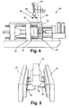
- a die casting machine 60 shown in FIG. 4 also includes a casting mold 62 a fixed first mold half fixed on a machine stand 64 66 and a movable on a movable carriage 70 second mold half 68.
- the mold 62 is closed, i.e. the both mold halves 66, 68 are during hydraulically generated forces the duration of a casting process with formation of a closed mold cavity pressed against each other.
- a spray head 76 Above the casting mold 62, one on a holder 72 is horizontal and vertical displaceably mounted spray device 74 is arranged with a spray head 76. Bendable spray pipes 78 with spray nozzles attached protrude from the spray head 76 80 off. Compressed air and release agent solution are applied via lines 82, 84 the central spray head 76 brought up and via the spray pipes 78 to the Spray nozzles 80 directed.
- the spray head 76 is located between the two mold halves 66, 68 of the opened mold 62.
- the spray pipes 78 with the attached Spray nozzles 80 are in a predetermined arrangement on the shaping Surfaces of the two mold halves 66, 68 directed.
Landscapes
- Engineering & Computer Science (AREA)
- Mechanical Engineering (AREA)
- Casting Devices For Molds (AREA)
- Nozzles (AREA)
- Fire-Detection Mechanisms (AREA)
Abstract
Description
- Fig. 1 einen Längsschnitt durch eine Sprühdüse;
- Fig. 2 eine Schrägsicht auf den Düsenkopf der Sprühdüse von Fig. 1 in vergrösserter Darstellung;
- Fig. 3 einen Längsschnitt durch den Düsenkopf von Fig. 2;
- Fig. 4 eine Seitenansicht einer Druckgiessmaschine mit einer Sprühvorrichtung mit einem Sprühkopf;
- Fig. 5 eine Schrägsicht auf den zwischen den beiden Formhälften einer Giessform positionierten Sprühkopf von Fig. 4 in vergrösserter Darstellung.
Claims (7)
- Sprühdüse mit einem Düsenteil (12) zum Auftragen von Trennmittel auf die Mantelfläche eines Verdichters oder eines Kerns in einer Giessform einer Druckgiessmaschine,
dadurch gekennzeichnet, dass
am Kopf (14) des Düsenteils (12) eine Vielzahl von Austrittskanälen (20) mit symmetrisch zu einer Düsenachse (a) auf einer Kegelmantelfläche liegenden Sprühachsen (b) angeordnet ist und dem Düsenteil (12) in Sprührichtung ein rohrförmiges Düsenaufsatzteil (24) mit einer axialsymmetrisch zur Düsenachse (a) verlaufenden Innenwand (26) vorgesetzt ist, wobei die durch die Sprühachsen (b) definierte Kegelmantelfläche die Innenwand (26) des Düsenaufsatzteils (24) schneidet. - Sprühdüse nach Anspruch 1, dadurch gekennzeichnet, dass die Innenwand (26) des Düsenaufsatzteils (24) einen zylindrischen Innenwandteil (30) aufweist und die durch die Sprühachsen (b) definierte Kegelmantelfläche den zylindrischen Innenwandteil (30) schneidet.
- Sprühdüse nach Anspruch 2, dadurch gekennzeichnet, dass die Innenwand (26) des Düsenaufsatzteils (24) in Sprührichtung nacheinander einen konisch sich erweiternden Innenwandteil (28), den zylindrischen Innenwandteil (30) und einen konisch zulaufenden Innenwandteil (52) aufweist.
- Sprühdüse nach einem der Ansprüche 1 bis 3, dadurch gekennzeichnet, dass die Sprühachsen (d) mit der Düsenachse (a) einen Winkel (α) von 10 bis 30° einschliessen.
- Sprühdüse nach einem der Ansprüche 1 bis 4, dadurch gekennzeichnet, dass sie eine Zweistoffdüse ist und der Sprühwinkel (β) der von den Austrittskanälen (20) gebildeten Einzeldüsen max. 25° beträgt.
- Sprühdüse nach einem der Ansprüche 1 bis 5, dadurch gekennzeichnet, dass das Düsenaufsatzteil (24) mit dem Düsenteil (12) lösbar verschraubt ist.
- Verwendung einer Sprühdüse (10) nach einem der vorhergehenden Ansprüche zum Zerstäuben von wässrigen Trennmittelgemischen in der Form einer Lösung, Emulsion oder Suspension und Auftragen des zerstäubten Trennmittel/Wasser-Gemisches auf die Mantelfläche eines koaxial zur Düsenachse positionierten Verdichters oder Kerns einer Giessform einer Druckgiessmaschine.
Priority Applications (3)
| Application Number | Priority Date | Filing Date | Title |
|---|---|---|---|
| AT03405086T ATE336318T1 (de) | 2003-02-14 | 2003-02-14 | Sprühdüse |
| EP03405086A EP1447161B1 (de) | 2003-02-14 | 2003-02-14 | Sprühdüse |
| DE50304650T DE50304650D1 (de) | 2003-02-14 | 2003-02-14 | Sprühdüse |
Applications Claiming Priority (1)
| Application Number | Priority Date | Filing Date | Title |
|---|---|---|---|
| EP03405086A EP1447161B1 (de) | 2003-02-14 | 2003-02-14 | Sprühdüse |
Publications (2)
| Publication Number | Publication Date |
|---|---|
| EP1447161A1 true EP1447161A1 (de) | 2004-08-18 |
| EP1447161B1 EP1447161B1 (de) | 2006-08-16 |
Family
ID=32669062
Family Applications (1)
| Application Number | Title | Priority Date | Filing Date |
|---|---|---|---|
| EP03405086A Expired - Lifetime EP1447161B1 (de) | 2003-02-14 | 2003-02-14 | Sprühdüse |
Country Status (3)
| Country | Link |
|---|---|
| EP (1) | EP1447161B1 (de) |
| AT (1) | ATE336318T1 (de) |
| DE (1) | DE50304650D1 (de) |
Citations (4)
| Publication number | Priority date | Publication date | Assignee | Title |
|---|---|---|---|---|
| US2941729A (en) * | 1955-04-26 | 1960-06-21 | Wrightway Engineering Co | Hose nozzle with aerator |
| CH564978A5 (de) * | 1972-07-12 | 1975-08-15 | Grolitsch Erhard | |
| US4494699A (en) * | 1981-10-21 | 1985-01-22 | Hengesbach Robert W | Adjustable spray nozzle |
| DE3431253A1 (de) * | 1984-08-24 | 1986-03-06 | Bayrisches Druckgußwerk Thurner GmbH & Co KG, 8015 Markt Schwaben | Vorrichtung zum benetzen von formoberflaechen mit einer fluessigkeit |
-
2003
- 2003-02-14 AT AT03405086T patent/ATE336318T1/de not_active IP Right Cessation
- 2003-02-14 DE DE50304650T patent/DE50304650D1/de not_active Expired - Fee Related
- 2003-02-14 EP EP03405086A patent/EP1447161B1/de not_active Expired - Lifetime
Patent Citations (4)
| Publication number | Priority date | Publication date | Assignee | Title |
|---|---|---|---|---|
| US2941729A (en) * | 1955-04-26 | 1960-06-21 | Wrightway Engineering Co | Hose nozzle with aerator |
| CH564978A5 (de) * | 1972-07-12 | 1975-08-15 | Grolitsch Erhard | |
| US4494699A (en) * | 1981-10-21 | 1985-01-22 | Hengesbach Robert W | Adjustable spray nozzle |
| DE3431253A1 (de) * | 1984-08-24 | 1986-03-06 | Bayrisches Druckgußwerk Thurner GmbH & Co KG, 8015 Markt Schwaben | Vorrichtung zum benetzen von formoberflaechen mit einer fluessigkeit |
Also Published As
| Publication number | Publication date |
|---|---|
| EP1447161B1 (de) | 2006-08-16 |
| ATE336318T1 (de) | 2006-09-15 |
| DE50304650D1 (de) | 2006-09-28 |
Similar Documents
| Publication | Publication Date | Title |
|---|---|---|
| DE69122988T2 (de) | Niederdruck-Spritzpistole | |
| AT395555B (de) | Vorrichtung zum spritzgiessen von hohlraeume enthaltenden gegenstaenden aus kunststoff | |
| DE3234829C2 (de) | ||
| DE2418658A1 (de) | Spritzgiessform | |
| DE3709543C2 (de) | Vorrichtung zum Zerstäuben einer Flüssigkeit | |
| EP0190340B1 (de) | Vorrichtung zum benetzen von formoberflächen mit einer flüssigkeit | |
| DE69213182T2 (de) | Verfahren und Vorrichtung zum Entgraten | |
| EP0099045A1 (de) | Verfahren und Mischkopf zum Herstellen eines Kunststoff bildenden Reaktionsgemisches aus mindestens zwei fliessfähigen Reaktionskomponenten | |
| DE3781983T2 (de) | Verfahren und vorrichtung zum strangpressen, insbesondere von essbaren massen. | |
| DE3629696C2 (de) | ||
| DE3706694A1 (de) | Zweistoff-zerstaeubungsduese zur erzeugung eines vollkegelstrahls | |
| DE1274338B (de) | Strangpresskopf zur Herstellung von rohrfoermigen Pressteilen aus thermoplastischem Material | |
| EP1447161A1 (de) | Sprühdüse | |
| DE4312994C2 (de) | Vorrichtung zur Verspritzung von Suspensionen, insbesondere Mörteln | |
| EP0189099A1 (de) | Düse zur Texturierung eines Fadens | |
| DE69400060T2 (de) | Flachstrahldüse, insbesondere für Hochdruckreiniger | |
| DE3709666C1 (en) | Spray head of a spray device for release agents | |
| DE19713874B4 (de) | Vorrichtung zur Einleitung von Gas in ein Formwerkzeug | |
| EP3088087A1 (de) | Sprühdüse und verfahren zum erzeugen von nicht runden sprühkegeln | |
| DE10153159B4 (de) | Ventil | |
| DE19947434B4 (de) | Vorrichtung und Verfahren zum Herstellen von Kunststoff-Wellrohren | |
| EP1112108B1 (de) | Löschdüsenkopf zum ausbringen von löschflüssigkeit | |
| DE3833506C2 (de) | ||
| DE2526900A1 (de) | Spruehkopf | |
| WO2020254468A1 (de) | Vorrichtung zum auftragen eines trennmittels bei geschlossenem kernkasten |
Legal Events
| Date | Code | Title | Description |
|---|---|---|---|
| PUAI | Public reference made under article 153(3) epc to a published international application that has entered the european phase |
Free format text: ORIGINAL CODE: 0009012 |
|
| AK | Designated contracting states |
Kind code of ref document: A1 Designated state(s): AT BE BG CH CY CZ DE DK EE ES FI FR GB GR HU IE IT LI LU MC NL PT SE SI SK TR |
|
| AX | Request for extension of the european patent |
Extension state: AL LT LV MK RO |
|
| 17P | Request for examination filed |
Effective date: 20050218 |
|
| AKX | Designation fees paid |
Designated state(s): AT BE BG CH CY CZ DE DK EE ES FI FR GB GR HU IE IT LI LU MC NL PT SE SI SK TR |
|
| GRAP | Despatch of communication of intention to grant a patent |
Free format text: ORIGINAL CODE: EPIDOSNIGR1 |
|
| GRAS | Grant fee paid |
Free format text: ORIGINAL CODE: EPIDOSNIGR3 |
|
| GRAA | (expected) grant |
Free format text: ORIGINAL CODE: 0009210 |
|
| AK | Designated contracting states |
Kind code of ref document: B1 Designated state(s): AT CH DE FR IT LI NL |
|
| PG25 | Lapsed in a contracting state [announced via postgrant information from national office to epo] |
Ref country code: IT Free format text: LAPSE BECAUSE OF FAILURE TO SUBMIT A TRANSLATION OF THE DESCRIPTION OR TO PAY THE FEE WITHIN THE PRESCRIBED TIME-LIMIT;WARNING: LAPSES OF ITALIAN PATENTS WITH EFFECTIVE DATE BEFORE 2007 MAY HAVE OCCURRED AT ANY TIME BEFORE 2007. THE CORRECT EFFECTIVE DATE MAY BE DIFFERENT FROM THE ONE RECORDED. Effective date: 20060816 |
|
| REG | Reference to a national code |
Ref country code: CH Ref legal event code: EP |
|
| REF | Corresponds to: |
Ref document number: 50304650 Country of ref document: DE Date of ref document: 20060928 Kind code of ref document: P |
|
| ET | Fr: translation filed | ||
| PLBE | No opposition filed within time limit |
Free format text: ORIGINAL CODE: 0009261 |
|
| STAA | Information on the status of an ep patent application or granted ep patent |
Free format text: STATUS: NO OPPOSITION FILED WITHIN TIME LIMIT |
|
| 26N | No opposition filed |
Effective date: 20070518 |
|
| PGFP | Annual fee paid to national office [announced via postgrant information from national office to epo] |
Ref country code: CH Payment date: 20080228 Year of fee payment: 6 |
|
| PGFP | Annual fee paid to national office [announced via postgrant information from national office to epo] |
Ref country code: IT Payment date: 20080226 Year of fee payment: 6 Ref country code: NL Payment date: 20080224 Year of fee payment: 6 |
|
| PGFP | Annual fee paid to national office [announced via postgrant information from national office to epo] |
Ref country code: AT Payment date: 20080122 Year of fee payment: 6 |
|
| PGFP | Annual fee paid to national office [announced via postgrant information from national office to epo] |
Ref country code: DE Payment date: 20080331 Year of fee payment: 6 Ref country code: FR Payment date: 20080218 Year of fee payment: 6 |
|
| REG | Reference to a national code |
Ref country code: CH Ref legal event code: PL |
|
| PG25 | Lapsed in a contracting state [announced via postgrant information from national office to epo] |
Ref country code: LI Free format text: LAPSE BECAUSE OF NON-PAYMENT OF DUE FEES Effective date: 20090228 Ref country code: AT Free format text: LAPSE BECAUSE OF NON-PAYMENT OF DUE FEES Effective date: 20090214 Ref country code: CH Free format text: LAPSE BECAUSE OF NON-PAYMENT OF DUE FEES Effective date: 20090228 |
|
| NLV4 | Nl: lapsed or anulled due to non-payment of the annual fee |
Effective date: 20090901 |
|
| REG | Reference to a national code |
Ref country code: FR Ref legal event code: ST Effective date: 20091030 |
|
| PG25 | Lapsed in a contracting state [announced via postgrant information from national office to epo] |
Ref country code: NL Free format text: LAPSE BECAUSE OF NON-PAYMENT OF DUE FEES Effective date: 20090901 |
|
| PG25 | Lapsed in a contracting state [announced via postgrant information from national office to epo] |
Ref country code: DE Free format text: LAPSE BECAUSE OF NON-PAYMENT OF DUE FEES Effective date: 20090901 |
|
| PG25 | Lapsed in a contracting state [announced via postgrant information from national office to epo] |
Ref country code: FR Free format text: LAPSE BECAUSE OF NON-PAYMENT OF DUE FEES Effective date: 20090302 |
|
| PG25 | Lapsed in a contracting state [announced via postgrant information from national office to epo] |
Ref country code: IT Free format text: LAPSE BECAUSE OF NON-PAYMENT OF DUE FEES Effective date: 20090214 |