EP1447122A2 - Verfahren und Vorrichtung zur Reduzierung des aerosolbedingten Austrages aus einer Trennkolonne - Google Patents
Verfahren und Vorrichtung zur Reduzierung des aerosolbedingten Austrages aus einer Trennkolonne Download PDFInfo
- Publication number
- EP1447122A2 EP1447122A2 EP04002782A EP04002782A EP1447122A2 EP 1447122 A2 EP1447122 A2 EP 1447122A2 EP 04002782 A EP04002782 A EP 04002782A EP 04002782 A EP04002782 A EP 04002782A EP 1447122 A2 EP1447122 A2 EP 1447122A2
- Authority
- EP
- European Patent Office
- Prior art keywords
- separation
- installation
- partially flooded
- gaseous
- aerosols
- Prior art date
- Legal status (The legal status is an assumption and is not a legal conclusion. Google has not performed a legal analysis and makes no representation as to the accuracy of the status listed.)
- Granted
Links
Images

Classifications
-
- B—PERFORMING OPERATIONS; TRANSPORTING
- B01—PHYSICAL OR CHEMICAL PROCESSES OR APPARATUS IN GENERAL
- B01D—SEPARATION
- B01D45/00—Separating dispersed particles from gases or vapours by gravity, inertia, or centrifugal forces
- B01D45/04—Separating dispersed particles from gases or vapours by gravity, inertia, or centrifugal forces by utilising inertia
- B01D45/08—Separating dispersed particles from gases or vapours by gravity, inertia, or centrifugal forces by utilising inertia by impingement against baffle separators
- B01D45/10—Separating dispersed particles from gases or vapours by gravity, inertia, or centrifugal forces by utilising inertia by impingement against baffle separators which are wetted
-
- B—PERFORMING OPERATIONS; TRANSPORTING
- B01—PHYSICAL OR CHEMICAL PROCESSES OR APPARATUS IN GENERAL
- B01D—SEPARATION
- B01D3/00—Distillation or related exchange processes in which liquids are contacted with gaseous media, e.g. stripping
- B01D3/14—Fractional distillation or use of a fractionation or rectification column
-
- B—PERFORMING OPERATIONS; TRANSPORTING
- B01—PHYSICAL OR CHEMICAL PROCESSES OR APPARATUS IN GENERAL
- B01D—SEPARATION
- B01D53/00—Separation of gases or vapours; Recovering vapours of volatile solvents from gases; Chemical or biological purification of waste gases, e.g. engine exhaust gases, smoke, fumes, flue gases, aerosols
- B01D53/14—Separation of gases or vapours; Recovering vapours of volatile solvents from gases; Chemical or biological purification of waste gases, e.g. engine exhaust gases, smoke, fumes, flue gases, aerosols by absorption
- B01D53/18—Absorbing units; Liquid distributors therefor
Definitions
- the invention relates to a method for reducing the aerosol-related discharge a separation column, a device and a use.
- Thermodynamically stable suspensions of solid or liquid particles are used as aerosols referred to in gases, the upper limit for the particle diameter in the Usually a value of about 10 ⁇ m is given.
- Drop separators such as cyclones or deflection separators, all based on the principle of inertial separation based.
- the object of the invention was to provide a method which makes it possible to to retrofit existing separation columns economically in such a way that they meet new requirements for air pollution control.
- it is said to be an aerosol Discharge from separation columns should be reduced or avoided, or recyclables should be used can be obtained by using aerosols in an economical manner effective separation mechanisms (inertia and diffusion).
- the solution consists of a process to reduce the aerosol-related discharge from a separation column in which from a gaseous or liquid starting mixture one or more components are separated on internally effective internals, whereby in a gas phase in the separation column aerosols are present or are formed, wherein the segmented internals are segmented at one or more separation points and the separation point (s) is determined in such a way that the aerosols at the separation point (s) have at least 50% of their maximum particle size and being at each separation point provides for an installation that is at least partially flooded, under training a continuous liquid phase at least in parts of the installation to which the aerosols are attached be bound.
- the method according to the invention thus provides a simple constructive solution Provided an economical way to design new apparatus to be built as well as for retrofitting existing equipment, according to which aerosols inexpensive, using the effective separation mechanisms (inertia and diffusion) can be separated.
- separating column is understood to mean all apparatus which are in the Process technology for performing thermal separation processes can be used. These include in particular distillation columns, reactive distillation columns, reaction columns, Reactive extraction columns, absorption columns (gas scrubbers), desorption columns (Stripping columns) Adsorption columns or apparatus for carrying out Membrane separation processes.
- the method according to the invention relates in particular to the improvement of absorption columns, also referred to as gas scrubbers.
- Gas washers are widely used in process engineering. They are generally tubular devices with internal diameters in the range from 100 to 8000 mm, which are used to separate one or more components from a gas mixture by absorption into a washing liquid. These can be undesirable components ("air-foreign" substances), in processes for air pollution control or, on the contrary, valuable substances.
- gas scrubbers are equipped with separating internals, such as fillings, organized packings or floors.
- aerosols can form according to all known formation mechanisms, in particular reaction aerosols and / or condensation aerosols and / or sublimation aerosols. Aerosols can only exist temporarily, that is, they can only be present in partial areas of the gas scrubber.
- one the separation point (s) determines that the aerosols at the separation point (s) at least Have 50% of their maximum particle size.
- particle size is understood to mean the average mass-related diameter of a particle distribution, as is defined, for example, in Löffler, "Dust separation", Thieme-Verlag Stuttgart, 1988, p. 9, equation (1.20).
- the mean mass-related diameter is the cubic root from the third moment M 3.0 of the particle distribution.
- Particle distributions are determined by measurement using size-resolving measurement methods known to those skilled in the art.
- an isothermal equilibrium stage for the condensation process is now calculated for the gas phase.
- the actual degree of saturation S is greater than the corresponding equilibrium value S * , condensation can in principle take place on the particles which act as nuclei. This process is called activation of the particles. If, on the other hand, the actual degree of saturation is less than the corresponding equilibrium value S * , the size of the particles can shrink due to evaporation.
- the equilibrium value S * is therefore referred to as the critical degree of saturation, the associated particle radius as the critical particle radius R * p .
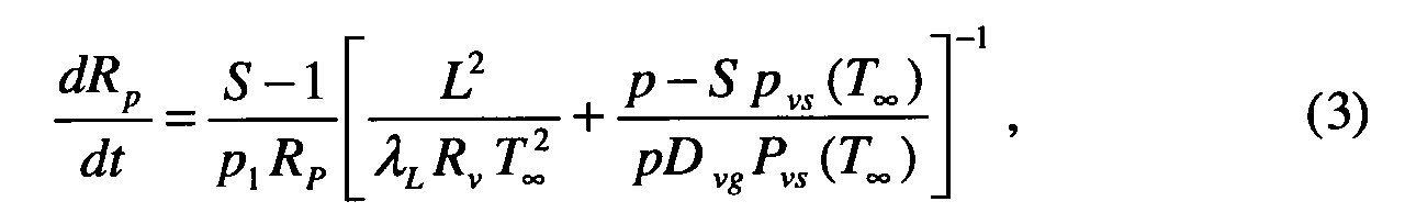
- the information about the segment-dependent degrees of saturation S i is used in another computer program with the help of one or more further equations to describe the particle growth over time t.
- This can be done using equation (3), for example.
- S the degree of saturation p 1 the density of the particles (liquid)
- L the latent heat of condensation
- ⁇ L the thermal conductivity of the surrounding medium
- R v the gas constant of the vapor
- p the total pressure of the gas phase in the separation column
- D vg the diffusion constant of the vapor in the ambient medium
- p vs describe the partial pressure of the vapor in the saturated state
- T ⁇ the temperature of the surrounding medium at an infinite distance from the particle surface.
- the point or points of separation are calculated as described above were an installation or fixtures provided in an at least partially flooded Operating state.
- partially flooded means that in areas of the installation that do not have to be contiguous, a continuous Liquid phase is forced.
- the separation point (s) is preferably determined such that the aerosols there are at least 80 % of their maximum particle size.
- the separation point (s) is particularly preferably determined such that the aerosols there are at least 90% of their maximum particle size exhibit.
- the separating internals are on one segmented single separation point.
- the installation or the installations at the separation point (s) can cover the entire inner diameter fill in the separation column, but it is also possible to install (the internals) in such a way that he (she) only the inside diameter of the separation column partially fills out. This can be particularly advantageous to at least one partially flooded operating state of the installation due to the higher gas velocity easier to achieve by the installation.
- the Fillers can basically take on any geometry, structured packings, floors, which are operated with a bubble layer as well as knitted fabrics, knitted fabrics or fleeces made of metals, plastics or glass.
- an external liquid supply and / or -discharge generates a defined pressure loss independent of the gas flow through the installation become.
- a pressure loss over the installation in the range of 0 to is advantageous 200 mbar, preferably in the range from 5 to 40 mbar.
- the at least partial flooding of the installation can take place in the separation column for absorption guided washing liquid, via liquid drops, from the gas flow into the installation be entered, generated.
- An external fluid supply is also possible for installation, the externally supplied liquid having the same composition as the Has washing liquid or may be different.
- Heights of the internals in the range from 100 to 500 mm are preferred.
- the method is not restricted with regard to the flow of electricity to be cleaned Gas mixture and washing liquid; Co-current and counter-current operation are the same possible.
- the process is not restricted in terms of operating pressure and temperature. Possible is an operation at atmospheric pressure, under or over pressure, with or without external Heat supply and dissipation.
- the invention also relates to a separation column in which a gaseous Starting mixture separated one or more components on separable internals are, wherein aerosols are present or formed in a gas phase, the is characterized in that it is segmented at one or more separation points, the one defines, as defined in one of claims 1 to 3, that it is present at each separation point an installation is equipped, which one operates as defined in claim 1 and that one via an external liquid supply and / or discharge at least partially flooded Installation (at the at least partially flooded installations) a defined Pressure loss generated.
- the pressure drop at the at least partially flooded installation in the range from 0 to 200 mbar, in particular in the range from 5 to 40 mbar.
- the separation column is advantageously segmented at a single separation point.
- the at least partially flooded installation (which at least partially flooded internals) designed such that the inner diameter the separation column is only partially filled.
- the at least partially flooded installation is preferably a packed bed, a structured pack with a bubble layer with continuous liquid and disperser gaseous phase operated floor or a knitted, knitted or non-woven metal, Plastic or glass.
- partially flooded internals with specific surfaces in the range from 60 to 2500 m 2 / m 3 and porosities in the range from 85 to 98%, preferably in the range from 91 to 96%.
- the separation column is preferably a gas scrubber to which a gaseous starting mixture is added and supplies a washing liquid, preferably in countercurrent.
- the process according to the invention and the separation column according to the invention are special Suitable for cleaning gas mixtures that form the formation of condensation aerosols tend, especially of gas streams, the gaseous hydrogen halides, in particular Hydrogen chloride and / or hydrogen bromide, gaseous sulfur trioxide, gaseous Contain sulfuric acid or gaseous nitrogen dioxide.
- gaseous hydrogen halides in particular Hydrogen chloride and / or hydrogen bromide
- gaseous sulfur trioxide gaseous Contain sulfuric acid or gaseous nitrogen dioxide.
- reaction aerosols tend, in particular of gas mixtures containing gaseous ammonia and gaseous Hydrogen chloride. Reaction mixtures may also be mentioned as examples Combustion processes.
- Another advantageous use relates to the cleaning of gas mixtures which are used for Formation of sublimation aerosols tend.
- the method according to the invention has increased flexibility since the Flow velocity of the gas phase over a wide operating range without significant Influencing the separation performance can be varied by the liquid dosage for at least partially flooded installation external, for example via a differential pressure measurement, is regulated.
- Another advantage of the method according to the invention is that the operating temperature is low, which is the absorption process of numerous gas components into an aqueous Washing solution significantly improved.
- the low operating temperatures are particularly advantageous when using corrosive material systems, for example mixtures containing hydrogen halide, since the material stress is thereby lower.
- a circular procedure in processes for the absorption of gas mixtures containing hydrogen halides, in particular hydrogen chloride makes it possible to prepare highly concentrated hydrohalic acid solutions, in particular highly concentrated hydrochloric acid solutions.
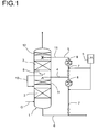
- FIG. 1 shows a gas scrubber 1, the one in the lower area the same, the gaseous starting mixture G and, in countercurrent to this, the washing liquid L supplied and in conventional separating internals 2 with each other Be brought in contact.
- pressure and composition profile in the gas scrubber 1 can be equipped with separating internals 2 in the lower one Area of the same aerosol formation by gas phase reaction and / or condensation and / or desublimation take place.
- the aerosol-laden gas flow from this area of the gas scrubber then flows through an installation 3, which is partial or complete flooded is operated. This is possible, for example, by installing 3 washing liquid from the area of the gas scrubber 1 located above or via an external one Lead 4 is supplied.
- the externally supplied liquid can be a container for Washing liquid 5 or the sump outlet 6 of the gas scrubber 1 via a return line 7 and a heat exchanger 8 are supplied.
- the aerosol-laden gas stream is transferred to a second, section of the gas scrubber 1 equipped with conventional separating internals 2 given, the separating internals 2 in this section of the apparatus both dry and also via an external feed line 11 with washing liquid for further absorptive Depletion can be operated under pressure.
- the washing liquid can also the container 5 or the sump outlet 6 of the gas scrubber via a return 7 and be supplied to a heat exchanger 8.
- a droplet separator is advantageous at the top of the column 12 provided for the entrainment of coarse drops (particle diameter >> 10 ⁇ m) in the cleaned gas stream, which is drawn off at the top of the column.
- the loaded washing liquid is withdrawn via the sump outlet of the gas scrubber 1.
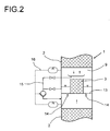
- FIG 2 shows a section from a further preferred embodiment of a gas scrubber 1 for performing the method according to the invention
- the installation 3 the is operated partially or completely flooded and between two areas with conventional separating internals 2 is arranged, and one compared to the inner diameter of the scrubber 1 has a smaller diameter.
- Installation 3 is in Gas fireplace of a tunnel floor 13 arranged on the particular one shown in FIG Liquid embodiment up to a certain height based on the installation 3 is pent up.
- the washing liquid is drained 14 from the tunnel floor 13 into the lower Area of the scrubber 1 passed.
- washing liquid can also be used an external line 10 with shut-off and conveyor facilities in the lower area of the Gas scrubber 1 are discharged.
- the withdrawn liquid flow can be measured using a differential pressure 15 are regulated, whereby a defined pressure drop at installation 3 can be adjusted.
- the effectiveness of the method according to the invention in the substance system water, hydrogen chloride, nitrogen was investigated in a test apparatus which was constructed in accordance with the schematic illustration in FIG. 2.
- the test apparatus consisted of a gas scrubber with an inner diameter of 100 mm, with two packings of 500 mm each made of commercially available plastic packing elements, namely Hiflow® rings from Rauschert with a specific surface area of 313 m 2 / m 3 and a porosity (gap size ) of 91%.
- An installation was inserted between the two packed beds, formed from a wire mesh droplet separator made of plastic, with a length of 150 mm and a diameter of 50 mm.
- Two wire mesh droplet separators which differed by their specific surface and porosity, were examined, namely a first wire mesh droplet separator with a smaller specific surface area, of 555 m 2 / m 3 and a porosity of 95.5%, and a second Wire mesh droplet separator with a larger specific surface area, of 615 m 2 / m 3 and a porosity of 93.8%.
- the first installation was partially flooded, the pressure loss across the installation was 10 mbar.
- the second installation was completely flooded, the pressure loss was 20 mbar.
- the test apparatus was operated isothermally at ambient pressure.
- a 1% by weight aqueous hydrochloric acid solution which was heated to a temperature of 22 ° C. was used as the washing liquid.
- the liquid loading of the column was 18 m 3 / m 2 / h.
- the dry gas stream to be cleaned of 14.6 Nm 3 / h of nitrogen was fed to the washing column with a constant hydrogen chloride concentration of 3100 ppm by volume and an inlet temperature of 25 ° C.
- Fine solid ammonium chloride particles in a concentration range of 10 5 to 4.5 ⁇ 10 7 particles / cm 3 were added to the gas stream to be cleaned as condensation nuclei for aerosol formation.
- the size of the germs can be estimated at 0.05 to 1 ⁇ m (see K. Schaber: Chem. Eng. Sci., 1995 (50), 8, p. 1347, Table 1).
- the double logarithmic representation in FIG. 3 shows the residual contents of hydrogen chloride in the cleaned gas stream, y HCl , in ppm by volume depending on the number of particles n in the gas stream to be cleaned, in 1 / cm 3 , for one gas scrubber according to the state of the art Technology (curve I, marked with triangles), and for a gas scrubber according to the invention, with a partially flooded installation (curve II, the measurement points are shown as circles) or with a flooded installation (curve III, the measurement points are shown as squares) ).
- test results show that the use according to the invention of an at least partially flooded installation in the entire particle concentration range reduces the hydrogen chloride concentration in the purified gas stream. Operation with a completely flooded installation proved to be particularly effective, which led to a purified gas flow with less than 30 ppm by volume of hydrogen chloride in the technically relevant bacterial count range up to 10 6 particles / cm 3 .
Abstract
Description
In Trennkolonnen, insbesondere in Gaswäschern können sich Aerosole, nach allen bekannten Bildungsmechanismen, insbesondere Reaktionsaerosole und/oder Kondensationsaerosole und/oder Sublimationsaerosole bilden. Aerosole können nur zwischenexistent sein, das heißt nur in Teilbereichen des Gaswäschers vorhanden sein.
Die messtechnische Bestimmung von Partikelverteilungen erfolgt, mit für den Fachmann bekannten größenauflösenden Messverfahren.
Die Erfindung wird im Folgenden anhand einer Figur sowie von Anwendungsbeispielen näher erläutert.
- Figur 1
- eine erste bevorzugte Ausführungsform eines Gaswäschers zur Durchführung des erfindungsgemäßen Verfahrens,
- Figur 2
- einen Ausschnitt aus einer weiteren bevorzugten Ausführungsform eines Gaswäschers zur Durchführung des erfindungsgemäßen Verfahrens und
- Figur 3
- die graphische Darstellung der Versuchsergebnisse zur Bestimmung der Reinigungsleistung eines Gaswäschers nach dem Stand der Technik mit Gegenüberstellung von Gaswäschern nach dem erfindungsgemäßen Verfahren.
Claims (19)
- Verfahren zur Reduzierung des aerosolbedingten Austrags aus einer Trennkolonne (1), in der aus einem gasförmigen oder flüssigen Ausgangsgemisch (G) eine oder mehrere Komponenten an trennwirksamen Einbauten (2) abgetrennt werden, wobei in einer Gasphase in der Trennkolonne (1) Aerosole vorhanden sind oder gebildet werden, dadurch gekennzeichnet, dass man die trennwirksamen Einbauten (2) an einer oder mehreren Trennstellen segmentiert, wobei man die Trennstelle(n) dergestalt bestimmt, dass die Aerosole an der oder den Trennstellen mindestens 50 % ihrer maximalen Partikelgröße aufweisen und dass man an jeder Trennstelle einen Einbau (3) vorsieht, den man zumindest partiell geflutet betreibt, wobei sich zumindest in Teilbereichen des Einbaus (3) eine kontinuierliche Flüssigphase ausbildet, an die die Aerosole gebunden werden.
- Verfahren nach Anspruch 1, dadurch gekennzeichnet, dass man die Trennstelle (n) an der Stelle (den Stellen) vorsieht, an der (den) die Aerosole mindestens 80 %, bevorzugt mindestens 90 % ihrer maximalen Partikelgröße aufweisen.
- Verfahren nach Anspruch 1 oder 2, dadurch gekennzeichnet, dass man die trennwirksamen Einbauten (2) an einer Trennstelle segmentiert.
- Verfahren nach einem der Ansprüche 1 bis 3, dadurch gekennzeichnet, dass der zumindest partiell geflutet betriebene Einbau (die zumindest partiell geflutet betriebenen Einbauten) (3) den Innendurchmesser der Trennkolonne (1) nur teilweise ausfüllt (ausfüllen).
- Verfahren nach einem der Ansprüche 1 bis 4, dadurch gekennzeichnet, dass der zumindest partiell geflutet betriebene Einbau (die zumindest partiell geflutet betriebenen Einbauten) (3) eine Füllkörperschüttung, eine strukturierte Packung, ein mit Sprudelschicht mit kontinuierlicher flüssiger und disperser gasförmiger Phase betriebener Boden oder ein Gestrick, Gewirk oder Vlies aus Metall, Kunststoff oder Glas ist (sind).
- Verfahren nach einem der Ansprüche 1 bis 5, dadurch gekennzeichnet, dass die spezifische Oberfläche des zumindest partiell geflutet betriebenen Einbaus (der zumindest partiell geflutet betriebenen Einbauten) (3) im Bereich von 60 bis 2500 m2/m3 und die Porosität im Bereich von 85 bis 98 %, bevorzugt im Bereich von 91 bis 96 %, liegt.
- Verfahren nach einem der Ansprüche 1 bis 6, dadurch gekennzeichnet, dass man der Trennkolonne (1) stromabwärts vor dem zumindest partiell geflutet betriebenen Einbau (den zumindest partiell geflutet betriebenen Einbauten) (3), bezogen auf die Zuführung des gasförmigen oder flüssigen Ausgangsgemisches (G), einen externen Gas-, Dampf- und/oder Flüssigkeitsstrom zuführt, den man dergestalt regelt, dass er die Sättigung oder Übersättigung der Gasphase in der Trennkolonne (1) bewirkt.
- Verfahren nach einem der Ansprüche 1 bis 7, dadurch gekennzeichnet, dass man über eine externe Flüssigkeitszu- und/oder -abführung (4, 10) am zumindest partiell geflutet betriebenen Einbau (an den zumindest partiell geflutet betriebenen Einbauten) (3) einen definierten Druckverlust erzeugt.
- Verfahren nach Anspruch 8, dadurch gekennzeichnet, dass der Druckverlust am zumindest partiell geflutet betriebenen Einbau (an den zumindest partiell geflutet betriebenen Einbauten) (3) im Bereich von 0 bis 200 mbar, bevorzugt im Bereich von 5 bis 40 mbar eingestellt wird.
- Verfahren nach einem der Ansprüche 1 bis 9, dadurch gekennzeichnet, dass die Trennkolonne (1) ein Gaswäscher ist, dem man ein gasförmiges Ausgangsgemisch (G) und eine Waschflüssigkeit (L), bevorzugt im Gegenstrom, zuführt.
- Trennkolonne (1), in der aus einem gasförmigen oder flüssigen Ausgangsgemisch (G) eine oder mehrere Komponenten an trennwirksamen Einbauten (2) abgetrennt werden, wobei in einer Gasphase Aerosole vorhanden sind oder gebildet werden, dadurch gekennzeichnet, dass die Trennkolonne (1) an einer oder mehreren Trennstellen segmentiert ist, die man dergestalt bestimmt, dass die Aerosole an der oder den Trennstellen mindestens 50 %, bevorzugt mindestens 80 %, besonders bevorzugt mindestens 90 % ihrer maximalen Partikelgröße aufweisen dass die Trennkolonne (1) an jeder Trennstelle mit einem Einbau (3) ausgestattet ist, den man zumindest partiell geflutet betreibt, wobei sich zumindest in Teilbereichen des Einbaus (3) eine kontinuierliche Flüssigphase ausbildet, an die die Aerosole gebunden werden und dass man über eine externe Flüssigkeitszu- und/oder -abführung (4, 10) am zumindest teilweise geflutet betriebenen Einbau (an den zumindest teilweise geflutet betriebenen Einbauten) (3) einen definierten Druckverlust erzeugt.
- Trennkolonne (1) nach Anspruch 11, dadurch gekennzeichnet, dass die trennwirksamen Einbauten an einer Trennstelle segmentiert sind.
- Trennkolonne (1) nach Anspruch 11 oder 12, dadurch gekennzeichnet, dass der zumindest partiell geflutet betriebene Einbau (die zumindest partiell geflutet betriebenen Einbauten) (3) den Innendurchmesser der Trennkolonne (1) nur teilweise ausfüllt (ausfüllen).
- Trennkolonne (1) nach einem der Ansprüche 11 bis 13, dadurch gekennzeichnet, dass der zumindest partiell geflutet betriebene Einbau (die zumindest geflutet betriebenen Einbauten) (3) eine Füllkörperschüttung, eine strukturierte Packung, ein mit Sprudelschicht mit kontinuierlicher flüssiger und disperser gasförmiger Phase betriebener Boden oder ein Gestrick, Gewirk oder Vlies aus Metall, Kunststoff ist (sind).
- Trennkolonne (1) nach einem der Ansprüche 11 bis 13, dadurch gekennzeichnet, dass die spezifische Oberfläche des zumindest partiell geflutet betriebenen Einbaus (der zumindest partiell geflutet betriebenen Einbauten) (3) im Bereich von 60 bis 2500 m2/m3 und die Porosität im Bereich von 85 bis 98 %, bevorzugt im Bereich von 91 bis 96 %, liegt.
- Vorrichtung nach einem der Ansprüche 11 bis 15, dadurch gekennzeichnet, dass die Trennkolonne (1) ein Gaswäscher ist, dem man ein gasförmiges Ausgangsgemisch (G) und eine Waschflüssigkeit (L), bevorzugt im Gegenstrom, zuführt.
- Verwendung eines Verfahrens nach einem der Ansprüche 1 bis 10 oder einer Trennkolonne (1) nach einem der Ansprüche 11 bis 16 zur Reinigung von Gasströmen, die zur Bildung von Kondensationsaerosolen neigen, insbesondere von Gasströmen, die gasförmige Halogenwasserstoffe, insbesondere Chlorwasserstoff und/oder Bromwasserstoff, gasförmiges Schwefeltrioxid, gasförmige Schwefelsäure oder gasförmiges Stickstoffdioxid enthalten, und die in Kontakt mit wässrigen Lösungen kommen, insbesondere mit wässrigen Lösungen, die Ionen enthalten, die bei der Absorption der vorgenannten Stoffe in Wasser entstehen.
- Verwendung eines Verfahrens nach einem der Ansprüche 1 bis 10 oder einer Trennkolonne (1) nach einem der Ansprüche 11 bis 16 zur Reinigung von Gasströmen, die zur Bildung von Reaktionsaerosolen neigen, insbesondere zur Reinigung von Gasströmen, die gasförmigen Ammoniak und gasförmigen Chlorwasserstoff enthalten.
- Verwendung eines Verfahrens nach einem der Ansprüche 1 bis 10 oder einer Trennkolonne (1) nach einem der Ansprüche 11 bis 16 zur Reinigung von Gasströmen, die zur Bildung von Sublimationsaerosolen neigen.
Applications Claiming Priority (2)
| Application Number | Priority Date | Filing Date | Title |
|---|---|---|---|
| DE10305578 | 2003-02-11 | ||
| DE10305578A DE10305578A1 (de) | 2003-02-11 | 2003-02-11 | Verfahren und Vorrichtung zur Reduzierung des aerosolbedingten Austrages aus einer Trennkolonne |
Publications (3)
| Publication Number | Publication Date |
|---|---|
| EP1447122A2 true EP1447122A2 (de) | 2004-08-18 |
| EP1447122A3 EP1447122A3 (de) | 2004-12-01 |
| EP1447122B1 EP1447122B1 (de) | 2006-09-27 |
Family
ID=32668015
Family Applications (1)
| Application Number | Title | Priority Date | Filing Date |
|---|---|---|---|
| EP04002782A Expired - Lifetime EP1447122B1 (de) | 2003-02-11 | 2004-02-09 | Verfahren und Vorrichtung zur Reduzierung des aerosolbedingten Austrages aus einer Trennkolonne |
Country Status (5)
| Country | Link |
|---|---|
| US (1) | US7025808B2 (de) |
| EP (1) | EP1447122B1 (de) |
| AT (1) | ATE340628T1 (de) |
| DE (2) | DE10305578A1 (de) |
| ES (1) | ES2273104T3 (de) |
Families Citing this family (9)
| Publication number | Priority date | Publication date | Assignee | Title |
|---|---|---|---|---|
| MY155337A (en) | 2008-06-30 | 2015-10-05 | Amt Int Inc | Wet-gas separator |
| US7842114B2 (en) * | 2008-07-18 | 2010-11-30 | Uop Llc | Vessel for receiving a fluid including a demister |
| CA2800994C (en) * | 2010-05-31 | 2015-12-08 | Mitsubishi Heavy Industries, Ltd. | Air pollution control system and method |
| EP2578295B1 (de) | 2010-05-31 | 2020-05-27 | Mitsubishi Heavy Industries Engineering, Ltd. | Abgasverarbeitungssystem und -verfahren |
| WO2011152547A1 (ja) | 2010-05-31 | 2011-12-08 | 三菱重工業株式会社 | 排ガス処理システム及び方法 |
| EP2689820A1 (de) | 2012-07-27 | 2014-01-29 | Nederlandse Organisatie voor toegepast -natuurwetenschappelijk onderzoek TNO | Aminreduktion in Aerosolen |
| US9265267B2 (en) | 2013-07-22 | 2016-02-23 | Garry Parkinson Isaacs | Open top liquid/gas cyclone separator tube and process for same |
| CA2940950C (en) * | 2015-09-03 | 2024-01-09 | Questor Technology Inc. | Method and system for reducing produced water disposal volumes utilizing waste heat |
| EP3181540B1 (de) * | 2015-12-18 | 2019-07-24 | L'Air Liquide Société Anonyme pour l'Etude et l'Exploitation des Procédés Georges Claude | Verfahren zur trennung von methanol aus gasgemischen |
Citations (5)
| Publication number | Priority date | Publication date | Assignee | Title |
|---|---|---|---|---|
| FR1074603A (fr) * | 1952-06-30 | 1954-10-07 | Still Carl | Tour à garnissage de ruissellement en métal déployé |
| DE2904143A1 (de) * | 1979-02-03 | 1981-01-08 | Leipzig Chemieanlagen | Gas(dampf)-fluessigkeitskontakteinrichtung fuer stoff- und waermeuebertragung im phasengleich- oder im phasengegenstrom |
| US4348373A (en) * | 1980-03-25 | 1982-09-07 | Haldor Topsoe A/S | Process for the preparation of sulfuric acid |
| US5660615A (en) * | 1995-02-16 | 1997-08-26 | Metallgesellschaft Ag | Exhaust gas scrubbing process |
| US6312503B1 (en) * | 1999-10-13 | 2001-11-06 | Arteva North America S.A.R.L. | System to quench gasses and remove condensables |
Family Cites Families (2)
| Publication number | Priority date | Publication date | Assignee | Title |
|---|---|---|---|---|
| DE69907616T2 (de) * | 1998-12-28 | 2004-03-11 | Nippon Sanso Corp. | Dampf-flüssig Kontaktor, kryogene Lufttrennungseinheit und Verfahren zur Gastrennung |
| JP3969949B2 (ja) * | 2000-10-25 | 2007-09-05 | 関西電力株式会社 | アミン回収方法及び装置並びにこれを備えた脱炭酸ガス装置 |
-
2003
- 2003-02-11 DE DE10305578A patent/DE10305578A1/de not_active Withdrawn
-
2004
- 2004-02-09 EP EP04002782A patent/EP1447122B1/de not_active Expired - Lifetime
- 2004-02-09 AT AT04002782T patent/ATE340628T1/de not_active IP Right Cessation
- 2004-02-09 ES ES04002782T patent/ES2273104T3/es not_active Expired - Lifetime
- 2004-02-09 DE DE502004001554T patent/DE502004001554D1/de not_active Expired - Lifetime
- 2004-02-11 US US10/775,097 patent/US7025808B2/en not_active Expired - Fee Related
Patent Citations (5)
| Publication number | Priority date | Publication date | Assignee | Title |
|---|---|---|---|---|
| FR1074603A (fr) * | 1952-06-30 | 1954-10-07 | Still Carl | Tour à garnissage de ruissellement en métal déployé |
| DE2904143A1 (de) * | 1979-02-03 | 1981-01-08 | Leipzig Chemieanlagen | Gas(dampf)-fluessigkeitskontakteinrichtung fuer stoff- und waermeuebertragung im phasengleich- oder im phasengegenstrom |
| US4348373A (en) * | 1980-03-25 | 1982-09-07 | Haldor Topsoe A/S | Process for the preparation of sulfuric acid |
| US5660615A (en) * | 1995-02-16 | 1997-08-26 | Metallgesellschaft Ag | Exhaust gas scrubbing process |
| US6312503B1 (en) * | 1999-10-13 | 2001-11-06 | Arteva North America S.A.R.L. | System to quench gasses and remove condensables |
Also Published As
| Publication number | Publication date |
|---|---|
| ES2273104T3 (es) | 2007-05-01 |
| ATE340628T1 (de) | 2006-10-15 |
| EP1447122B1 (de) | 2006-09-27 |
| US20040182241A1 (en) | 2004-09-23 |
| DE502004001554D1 (de) | 2006-11-09 |
| US7025808B2 (en) | 2006-04-11 |
| DE10305578A1 (de) | 2004-08-19 |
| EP1447122A3 (de) | 2004-12-01 |
Similar Documents
| Publication | Publication Date | Title |
|---|---|---|
| EP0727247B1 (de) | Verfahren zum Reinigen von Gasen mit Wasser | |
| DE19629500C1 (de) | Multiwäscher und Verfahren zur Totalreinigung von Gasen | |
| EP0953373A2 (de) | Verfahren zur Entfernung von Verunreinigungen aus einem Gasstrom | |
| EP2300126B1 (de) | Anlage und verfahren zur absorption von schadstoffen in gasen | |
| WO1995000805A1 (de) | Verfahren und einrichtung zum reinigen von abgasen | |
| DE2250471A1 (de) | Verfahren zur trennung von bestandteilen aus gasgemischen | |
| EP1447122B1 (de) | Verfahren und Vorrichtung zur Reduzierung des aerosolbedingten Austrages aus einer Trennkolonne | |
| WO2015036603A1 (de) | Verfahren und system zur gaswäsche von aerosolhaltigen prozessgasen | |
| DE2519996A1 (de) | Vorrichtung und verfahren zum inberuehrungbringen zweier fluide | |
| EP3615181B1 (de) | Vorrichtung und verfahren zur abgaswäsche | |
| WO1986004519A1 (en) | Purification plant and process for removing pollution from hot gases | |
| DE3629688C2 (de) | Verfahren zur Reinigung von Rauch- und anderen Industrieabgasen | |
| DE19751851A1 (de) | Aerosolminderung | |
| DE10024708B4 (de) | Verfahren zur Herstellung von Sauerstoffgas | |
| DE4342162C1 (de) | Waschturm für Rauchgasentschwefelungsanlagen und Verfahren zur Rauchgaswäsche | |
| EP2186556A1 (de) | Vorrichtung zum Abscheiden von Flüssigkeiten aus Gasströmen sowie Verfahren zur Entfeuchtung und/oder Entstaubung von Gas unter Verwendung wenigstens einer Vorrichtung zum Abscheiden von Flüssigkeiten aus Gasströmen | |
| DE4017410A1 (de) | Verfahren und vorrichtung zur herstellung von extrem reinem stickstoff | |
| AT403665B (de) | Verfahren und anlage zur abscheidung feinster oxidteilchen | |
| DE3816768C1 (de) | ||
| WO2018197281A1 (de) | Vorrichtung und verfahren zur abgaswäsche sowie harnstoffanlage mit einer abgaswäsche | |
| EP0968044A1 (de) | Verfahren zur unterdrückung der bildung von schwefelsaüreaerosolen in abgasreinigungsanlagen | |
| DE3117794C2 (de) | Verfahren zur Feinreinigung von Gasen | |
| WO2002078820A1 (de) | Verfahren zur aufreinigung von korrosiv wirkenden gasen | |
| EP0190649A2 (de) | Verfahren zur Abluftreinigung | |
| DE19638584C2 (de) | Verfahren zur Abscheidung von Staub aus einem staubhaltigen und wasserdampfhaltigen Abgas in einem filtrierenden Abscheider |
Legal Events
| Date | Code | Title | Description |
|---|---|---|---|
| PUAI | Public reference made under article 153(3) epc to a published international application that has entered the european phase |
Free format text: ORIGINAL CODE: 0009012 |
|
| AK | Designated contracting states |
Kind code of ref document: A2 Designated state(s): AT BE BG CH CY CZ DE DK EE ES FI FR GB GR HU IE IT LI LU MC NL PT RO SE SI SK TR |
|
| AX | Request for extension of the european patent |
Extension state: AL LT LV MK |
|
| PUAL | Search report despatched |
Free format text: ORIGINAL CODE: 0009013 |
|
| AK | Designated contracting states |
Kind code of ref document: A3 Designated state(s): AT BE BG CH CY CZ DE DK EE ES FI FR GB GR HU IE IT LI LU MC NL PT RO SE SI SK TR |
|
| AX | Request for extension of the european patent |
Extension state: AL LT LV MK |
|
| 17P | Request for examination filed |
Effective date: 20041216 |
|
| 17Q | First examination report despatched |
Effective date: 20050407 |
|
| AKX | Designation fees paid |
Designated state(s): AT BE BG CH CY CZ DE DK EE ES FI FR GB GR HU IE IT LI LU MC NL PT RO SE SI SK TR |
|
| GRAP | Despatch of communication of intention to grant a patent |
Free format text: ORIGINAL CODE: EPIDOSNIGR1 |
|
| GRAS | Grant fee paid |
Free format text: ORIGINAL CODE: EPIDOSNIGR3 |
|
| GRAA | (expected) grant |
Free format text: ORIGINAL CODE: 0009210 |
|
| AK | Designated contracting states |
Kind code of ref document: B1 Designated state(s): AT BE BG CH CY CZ DE DK EE ES FI FR GB GR HU IE IT LI LU MC NL PT RO SE SI SK TR |
|
| PG25 | Lapsed in a contracting state [announced via postgrant information from national office to epo] |
Ref country code: IT Free format text: LAPSE BECAUSE OF FAILURE TO SUBMIT A TRANSLATION OF THE DESCRIPTION OR TO PAY THE FEE WITHIN THE PRESCRIBED TIME-LIMIT;WARNING: LAPSES OF ITALIAN PATENTS WITH EFFECTIVE DATE BEFORE 2007 MAY HAVE OCCURRED AT ANY TIME BEFORE 2007. THE CORRECT EFFECTIVE DATE MAY BE DIFFERENT FROM THE ONE RECORDED. Effective date: 20060927 Ref country code: SK Free format text: LAPSE BECAUSE OF FAILURE TO SUBMIT A TRANSLATION OF THE DESCRIPTION OR TO PAY THE FEE WITHIN THE PRESCRIBED TIME-LIMIT Effective date: 20060927 Ref country code: RO Free format text: LAPSE BECAUSE OF FAILURE TO SUBMIT A TRANSLATION OF THE DESCRIPTION OR TO PAY THE FEE WITHIN THE PRESCRIBED TIME-LIMIT Effective date: 20060927 Ref country code: SI Free format text: LAPSE BECAUSE OF FAILURE TO SUBMIT A TRANSLATION OF THE DESCRIPTION OR TO PAY THE FEE WITHIN THE PRESCRIBED TIME-LIMIT Effective date: 20060927 Ref country code: IE Free format text: LAPSE BECAUSE OF FAILURE TO SUBMIT A TRANSLATION OF THE DESCRIPTION OR TO PAY THE FEE WITHIN THE PRESCRIBED TIME-LIMIT Effective date: 20060927 Ref country code: FI Free format text: LAPSE BECAUSE OF FAILURE TO SUBMIT A TRANSLATION OF THE DESCRIPTION OR TO PAY THE FEE WITHIN THE PRESCRIBED TIME-LIMIT Effective date: 20060927 Ref country code: CZ Free format text: LAPSE BECAUSE OF FAILURE TO SUBMIT A TRANSLATION OF THE DESCRIPTION OR TO PAY THE FEE WITHIN THE PRESCRIBED TIME-LIMIT Effective date: 20060927 |
|
| REG | Reference to a national code |
Ref country code: GB Ref legal event code: FG4D Free format text: NOT ENGLISH |
|
| RIN1 | Information on inventor provided before grant (corrected) |
Inventor name: HUBER, GUENTHER, DR. Inventor name: HOELEMANN, KARL, DR. Inventor name: LOENING, JAN-MARTIN, DR. Inventor name: SACHWEH, BERND DR. |
|
| REG | Reference to a national code |
Ref country code: CH Ref legal event code: EP |
|
| REG | Reference to a national code |
Ref country code: IE Ref legal event code: FG4D Free format text: LANGUAGE OF EP DOCUMENT: GERMAN |
|
| REF | Corresponds to: |
Ref document number: 502004001554 Country of ref document: DE Date of ref document: 20061109 Kind code of ref document: P |
|
| PG25 | Lapsed in a contracting state [announced via postgrant information from national office to epo] |
Ref country code: SE Free format text: LAPSE BECAUSE OF FAILURE TO SUBMIT A TRANSLATION OF THE DESCRIPTION OR TO PAY THE FEE WITHIN THE PRESCRIBED TIME-LIMIT Effective date: 20061227 Ref country code: BG Free format text: LAPSE BECAUSE OF FAILURE TO SUBMIT A TRANSLATION OF THE DESCRIPTION OR TO PAY THE FEE WITHIN THE PRESCRIBED TIME-LIMIT Effective date: 20061227 Ref country code: DK Free format text: LAPSE BECAUSE OF FAILURE TO SUBMIT A TRANSLATION OF THE DESCRIPTION OR TO PAY THE FEE WITHIN THE PRESCRIBED TIME-LIMIT Effective date: 20061227 |
|
| PG25 | Lapsed in a contracting state [announced via postgrant information from national office to epo] |
Ref country code: MC Free format text: LAPSE BECAUSE OF NON-PAYMENT OF DUE FEES Effective date: 20070228 |
|
| PG25 | Lapsed in a contracting state [announced via postgrant information from national office to epo] |
Ref country code: PT Free format text: LAPSE BECAUSE OF FAILURE TO SUBMIT A TRANSLATION OF THE DESCRIPTION OR TO PAY THE FEE WITHIN THE PRESCRIBED TIME-LIMIT Effective date: 20070313 |
|
| ET | Fr: translation filed | ||
| REG | Reference to a national code |
Ref country code: IE Ref legal event code: FD4D |
|
| REG | Reference to a national code |
Ref country code: ES Ref legal event code: FG2A Ref document number: 2273104 Country of ref document: ES Kind code of ref document: T3 |
|
| PLBE | No opposition filed within time limit |
Free format text: ORIGINAL CODE: 0009261 |
|
| STAA | Information on the status of an ep patent application or granted ep patent |
Free format text: STATUS: NO OPPOSITION FILED WITHIN TIME LIMIT |
|
| 26N | No opposition filed |
Effective date: 20070628 |
|
| PG25 | Lapsed in a contracting state [announced via postgrant information from national office to epo] |
Ref country code: GR Free format text: LAPSE BECAUSE OF FAILURE TO SUBMIT A TRANSLATION OF THE DESCRIPTION OR TO PAY THE FEE WITHIN THE PRESCRIBED TIME-LIMIT Effective date: 20061228 |
|
| PG25 | Lapsed in a contracting state [announced via postgrant information from national office to epo] |
Ref country code: AT Free format text: LAPSE BECAUSE OF NON-PAYMENT OF DUE FEES Effective date: 20070209 |
|
| PG25 | Lapsed in a contracting state [announced via postgrant information from national office to epo] |
Ref country code: EE Free format text: LAPSE BECAUSE OF FAILURE TO SUBMIT A TRANSLATION OF THE DESCRIPTION OR TO PAY THE FEE WITHIN THE PRESCRIBED TIME-LIMIT Effective date: 20060927 |
|
| PG25 | Lapsed in a contracting state [announced via postgrant information from national office to epo] |
Ref country code: CY Free format text: LAPSE BECAUSE OF FAILURE TO SUBMIT A TRANSLATION OF THE DESCRIPTION OR TO PAY THE FEE WITHIN THE PRESCRIBED TIME-LIMIT Effective date: 20060927 Ref country code: LU Free format text: LAPSE BECAUSE OF NON-PAYMENT OF DUE FEES Effective date: 20070209 |
|
| PG25 | Lapsed in a contracting state [announced via postgrant information from national office to epo] |
Ref country code: HU Free format text: LAPSE BECAUSE OF FAILURE TO SUBMIT A TRANSLATION OF THE DESCRIPTION OR TO PAY THE FEE WITHIN THE PRESCRIBED TIME-LIMIT Effective date: 20070328 Ref country code: TR Free format text: LAPSE BECAUSE OF FAILURE TO SUBMIT A TRANSLATION OF THE DESCRIPTION OR TO PAY THE FEE WITHIN THE PRESCRIBED TIME-LIMIT Effective date: 20060927 |
|
| PGFP | Annual fee paid to national office [announced via postgrant information from national office to epo] |
Ref country code: NL Payment date: 20140224 Year of fee payment: 11 Ref country code: CH Payment date: 20140225 Year of fee payment: 11 |
|
| PGFP | Annual fee paid to national office [announced via postgrant information from national office to epo] |
Ref country code: FR Payment date: 20140224 Year of fee payment: 11 Ref country code: ES Payment date: 20140321 Year of fee payment: 11 |
|
| PGFP | Annual fee paid to national office [announced via postgrant information from national office to epo] |
Ref country code: GB Payment date: 20140228 Year of fee payment: 11 |
|
| PGFP | Annual fee paid to national office [announced via postgrant information from national office to epo] |
Ref country code: BE Payment date: 20140327 Year of fee payment: 11 |
|
| PGFP | Annual fee paid to national office [announced via postgrant information from national office to epo] |
Ref country code: DE Payment date: 20140430 Year of fee payment: 11 |
|
| PG25 | Lapsed in a contracting state [announced via postgrant information from national office to epo] |
Ref country code: BE Free format text: LAPSE BECAUSE OF NON-PAYMENT OF DUE FEES Effective date: 20150228 |
|
| REG | Reference to a national code |
Ref country code: DE Ref legal event code: R119 Ref document number: 502004001554 Country of ref document: DE |
|
| REG | Reference to a national code |
Ref country code: NL Ref legal event code: V1 Effective date: 20150901 |
|
| PG25 | Lapsed in a contracting state [announced via postgrant information from national office to epo] |
Ref country code: NL Free format text: LAPSE BECAUSE OF NON-PAYMENT OF DUE FEES Effective date: 20150901 |
|
| REG | Reference to a national code |
Ref country code: CH Ref legal event code: PL |
|
| GBPC | Gb: european patent ceased through non-payment of renewal fee |
Effective date: 20150209 |
|
| PG25 | Lapsed in a contracting state [announced via postgrant information from national office to epo] |
Ref country code: CH Free format text: LAPSE BECAUSE OF NON-PAYMENT OF DUE FEES Effective date: 20150228 Ref country code: LI Free format text: LAPSE BECAUSE OF NON-PAYMENT OF DUE FEES Effective date: 20150228 |
|
| REG | Reference to a national code |
Ref country code: FR Ref legal event code: ST Effective date: 20151030 |
|
| PG25 | Lapsed in a contracting state [announced via postgrant information from national office to epo] |
Ref country code: GB Free format text: LAPSE BECAUSE OF NON-PAYMENT OF DUE FEES Effective date: 20150209 Ref country code: DE Free format text: LAPSE BECAUSE OF NON-PAYMENT OF DUE FEES Effective date: 20150901 |
|
| PG25 | Lapsed in a contracting state [announced via postgrant information from national office to epo] |
Ref country code: FR Free format text: LAPSE BECAUSE OF NON-PAYMENT OF DUE FEES Effective date: 20150302 |
|
| REG | Reference to a national code |
Ref country code: ES Ref legal event code: FD2A Effective date: 20160826 |
|
| PG25 | Lapsed in a contracting state [announced via postgrant information from national office to epo] |
Ref country code: ES Free format text: LAPSE BECAUSE OF NON-PAYMENT OF DUE FEES Effective date: 20150210 |